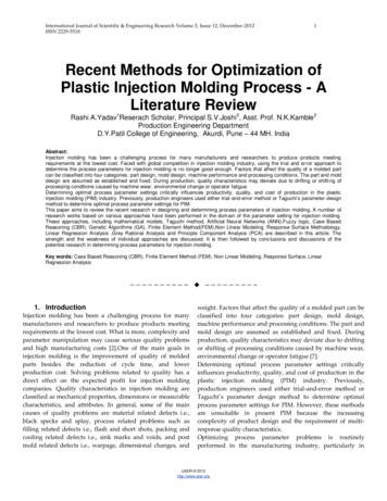
Transcription
Direct Injection Molding Tooling Inserts from theProcess with Copper PolyamideChristian Nelson, Jason Kepler, Rick Booth, Phillip ConnerDTM Corporation, Austin,The "RapidTool" Short Run (SR) Tooling Process using the Copper Polyamidematerial provides a route to mold inserts for injection molding made directly inthe Selective Laser Sintering machine. The STL files for the mold inserts areshelled and conformal cooling lines and ejector pin guides are added before SLSprocessing. Sintering of the material in the SLS machine provides quickmetal/plastic tooling with good thermal conductivity. Final preparation of thetooling inserts includes sealing the surface with epoxy, final finishing usingsandpaper, and backing up the shells with a metal alloy. The Copper PolyamideSR Tooling inserts are used to mold several hundred parts with common plasticswith injection cycle times similar to conventional molding cycle times.Rapid Prototyping and Rapid Tooling continue to change how products are designed and tested.Prototyping equipment used to make plastic models for visualization ten years ago is now used to· makeinvestment casting patterns, sand casting cores and molds, patterns for secondary processes, functionalprototypes, and mold inserts for injection molding.Market acceptance of Rapid Tooling continues to grow as designers realize the benefits of moldingprototype parts with the actual production material. DTM introduced RapidSteel 1.0 in 1996 for thecreation of steel/copper mold inserts [1]. DTM introduced the next generation of metal material in 1998.The RapidSteel 2.0 material provides improvements in processing time, finishing time, and accuracycompared to the original RapidSteel material. 3D Keltool was introduced by 3D Systems as a secondaryprocess to produce steel/copper inserts from a RP pattern [2]. Extrude Hone announced the ProMetalRTS-300 system for creating porous steel inserts using the three-dimensional printing (3DP) technologylicensed from MIT [3]. These processes require a furnace to sinter the steel and infiltrate the porous steelpart with a copper alloy. The resulting parts are fully dense and can be used to mold over 100,000 plasticparts with most plastics.Recently, a new breed of Rapid Tooling solutions has emerged to provide short runs of productionequivalent plastic parts. These limited runs of molded plastic parts are often used in the productdevelopment stage where several hundred parts in the final material are needed. The faster and moreeconomically a manufacturer can get a supply of parts produced in actual production materials, the fasterhe can perform life testing, make adjustments to the design if necessary, and get the new product on themarket.Methods of creating short run mold inserts available in today's market include direct manufacture usingRP, cast metal/epoxy tooling, and CNC machining. Mold inserts made directly in rapid prototypingdevices include SLA epoxy, SLS metal/plastic, and SLS direct metals [4]. The metal/plastic materialavailable for processing in the Selective Laser Sintering process is Copper Polyamide introduced in mid1998.451
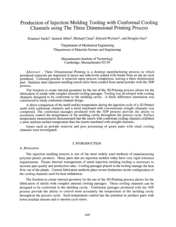
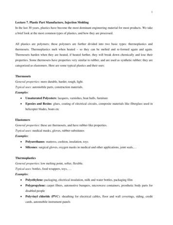
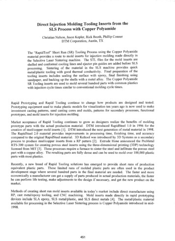
The Copper Polyamide material is a heat resistant, thermally conductive composite of copper and plasticthat was introduced for use with DTM's Sinterstation System. The Copper PA material processes in theSinterstation at conditions similar to the DuraForm Polyamide material. The Sinterstation builds the moldinserts directly from the geometry described in the STL file. Features like runners, gates, conformalcooling lines, and ejector pin guides are included in the STL file and built directly into the part.Turnaround times for the production of a mold insert are as short as a day. The key is that no furnaceprocess is involved.The Copper PA composite makes parts that are machinable and easily finished with wet sanding. Heatresistance and thermal conductivity are better than most plastic tooling materials, and it is possible tomold parts with cycle times that approach production rates. Injection mold inserts made with thismaterial are used to mold 100 to 400 parts in polystyrene (PS), polyethylene (PE), polypropylene (PP),glass filled polypropylene (GF PP), ABS, PC/ABS, and other common plastics.Mold PreparationInjection molding incorporates a cavity into which hot plasticized material is injected under pressure.Heat is removed from the material in the mold until it is rigid enough to be ejected so that the final partwill conform to all of its specifications. Both the design of the part and the design of the mold are criticalin insuring the right mold. While the design of the part is not within the scope of this paper, it shouldnevertheless be thoroughly reviewed by those people directly involved in the design of the mold and inthe molding operation [5].Before an injection mold is built the mold design must be established. Some basic considerations for themold include the type of gating, the thermal control system, the type of ejection, the type of venting, andanticipated shrinkage. With these items in mind, the designer defines a parting line and adds thenecessary features to the mold halves.When designing a mold for direct manufacture using SLS in the Sinterstation the cooling lines, ejector pinguides, gates, and runners can be included in the CAD design and built directly in the Sinterstation, seeFigures 1 and 2. Building these features directly into the mold saves time by reducing the man-hoursspent preparing the mold for injection molding.Adding the cooling lines to the CAD file is anadvantage because they can be placed nearcrucial mold features. The alternative toadding cooling lines to the CAD model isplacing copper tubing in the back of the moldhalf prior to backfilling. The copper tubingcan also be placed near critical mold features.However, placing copper tubing is moredifficult and time consuming than theplacement of virtual cooling lines in the CADmodel.Ejector pin location plays a critical role in thesuccess of the mold. A Copper PolyamideFigure I. Back surface of a mold core.mold requires 30 to 40 percent more ejectorpins than a standard aluminum tool. A d d i n g .more ejector pins makes part ejection easier which extends the lIfe of the mold. When applymg ejectorpin holes in the CAD file, the holes should be made the size of the ejector pin. These holes are reamed452
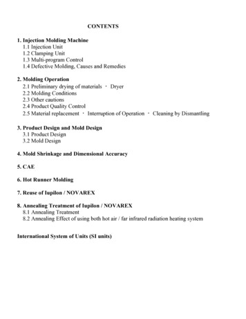
out during the mold-finishing phase. After the shelling operation, extend the ejector pin guides be?"on.dthe back surface of the mold to prevent the holes from becoming clogged when the backfill materIal ISadded.Runner and gate designs are important to mold lifeand part quality. Gates for the Copper Polyamidemolds should be larger than gates on an aluminumtool. The larger gate will keep the cavity pressuredown. On large molds, fan gates are recommended.On smaller molds, edge gates are used.When the CAD design of the mold is complete, themold half is shelled so that a backfill material can beadded to aid in the conduction of heat away from themold surface. The shelling operation is performedeither in the CAD package by operating on the solidmodel, or in a specialized application likeMaterialise's Magics RP [6] which operates on theSTL file. In this step, the mold is hollowed out suchthat the external surfaces have a wall thickness of 3.8mm. The bottom surface is then removed to provideaccess to the back surface of the mold face.RunnerFigure 2. Working surface of a mold core.If the cooling lines are added to the CAD file, thewall where the cooling lines enter/exit should be 12.5mm thick.Since the Copper Polyamide ismachinable the cooling line interface can be reamedand tapped for connecting the water source.When using a low melting metal alloy as a backfillmaterial, include a rib grid in the back of the mold tolock the alloy into the mold, see Figure 3. This ribgrid is not necessary if a metal filled epoxy is used asthe backfill material, see Figure 5.Figure 3. Rib-grid to lock in backfill material.SLS ProcessingAfter the mold design is complete and a STL file is created, the part is built using the Selective LaserSintering Process [7]. The Copper Polyamide material is processed with temperatures set points and scanparameters similar to those used to process DTM's other polyamide materials.The STL file in oriented so that the parting line is facing up with the longest dimension parallel to the xaxis, then rotated 15 degrees around the x-axis. The purpose of angling the part is to add strength to smallpost features.Sacrifice geometry is added at the top and bottom of the build to control the cooling rate. The additionallayer of scanned material acts as a heat fence reducing the thermal gradient within the part cake. Withoutthis barrier, the mold inserts would cool too quickly because of the good thermal conductivity of theCopper Polyamide material, resulting in curled or warped mold inserts. The sacrifice geometry can beany geometry that covers a majority of the build area and is at least 2 millimeters thick.453
Mold finishingAfter the mold insert is built in the Sinterstation, it is finished and prepared for molding. The finishingsteps include sealing the surface, finishing the surface, casting backfill material, machining ejector pinsand cooling line connections, and aligning the insert in the mold base.The Copper Polyamide parts as built in theSinterstation are porous. The inserts must besealed to prevent the molded plastic fromadhering to the surface and to prevent theconformal cooling lines from leaking. A lowviscosity epoxy or acrylate works well to sealthe surface. It is important to select a sealantthat can withstand high temperatures duringmolding. DTM recommends Imprex Superseal95-1000A, which is a heat cure acrylate.After sealing the part, the mold surface isfinished with a flexible sanding cloth, seeFigure 4. Start with 220 grit, then 320 grit, andfinally a 400 grit. Either wet or dry sandingtechniques can be used. Apply another coat ofsealer to the mold surface after sanding.The backfill material recommended by DTM isMetspec 217. This material is a metal alloywith a melting temperature of 103 C. TheMetspec is poured in layers to avoid softeningand deforming the mold insert. When thesesteps are complete, the mold insert is insertedinto the mold base. Different types of moldbases have been used successfully. If using atwo-plate type mold base, dowel holes can beadded to the CAD model in the comers of themold insert to aid in alignment. If using a oneplate pocketed base, conventional methods areused to square up the insert before placing themold insert into the pocketed base.L.Figure 5. Backfilling mold inserts with a metal filled epoxy.Molding TrialsThe mold inserts are fairly durable allowing a molding house to run the mold without special instructions.The durability of the Copper Polyamide mold inserts is similar to that of cast metal/epoxy tooling. Thethermal conductivity of the material is good, 1.28 W/m-K at 40 C, and is also similar to that of castmetaVepoxy tooling. The good thermal conductivity, in combination with the conformal cooling linesand a metal backfill material, allows the mold to be run with normal cycle times, typically 25 to 40seconds. The mechanical and thermal properties of SLS objects made with the Copper Polyamide arereported in Table 2.454
When molding, the mold should be at a consistent molding temperature before injection of the plastic.Try to get a full shot the first time. If there is a short shot, it is more likely to stick in the mold and causedamage. Mold release can be used at the beginning of the molding run. It is not necessary to apply moldrelease after every shot or late in the molding run. Several different release agents have been used withno problems.A number of common plastics have been successfully molded in the Copper Polyamide mold inserts. Themelting temperatures and processing temperatures for the plastics used in the mold inserts are listedbelow. In most cases, the mold inserts showed little or no wear and can be used to mold additional parts.Table 1 Examples of plastics successfully molded in Copper Polyamide mold inserts.MaterialMelting Temperature, CProcessing TemperatureRange, C (OF)Parts moldedPolyethyleneTm122 -137175 - 260 (350 - 500)50-350Polypropylene (PP)Tm160 -175190 - 285 (375 - 550)50-20010-40% talc filled PPTm158 -168175 - 285 (350 - 550)50-35040%GF PolypropyleneTm168230 - 285 (450 - 550)30 -150ASS (medium impact)Tg102 -115200 - 275 (390 - 525)40 -150ASS/PVCTg175 - 205185 - 210 (370 - 410)100 - 200Case Study #1: Brake fluid reservoir molded in polypropylene [8]Last spring at BASTECH, Inc [9], an automotive OEM client offered a challenging assignment. It needed20 to 50 sets of brake reservoir parts produced in the intended production material, polypropylene. Theparts had to withstand prolonged contact with brake fluid. Moreover, they had to perform like productionparts during functional testing on a prototype vehicle.BASTECH had faced a similar situation a year ago. Back then, the company had used 3D Systems' AIMTool process to create prototype tooling. The results were only marginally successful. After 10 shots withthe AIM Tool they began to see deformation of the parting line and the mold itself. The run producedonly 40 polypropylene parts, with each set becoming slightly more deformed.Wanting something better for this moldingrun, BASTECH used the Copper Polyamidematerial. The brake reservoir consisted oftwo pieces, which eventually would bewelded together. Two tools were required tomake these parts. One tool was made up of13 pieces; the other was made up of 6 pieces.Eight pieces of the thirteen-piece tool weremade using the Copper Polyamide (Figure6), as were five pieces of the six-piece tool.The remaining pieces, very simple inserts orsleeves, were machined out of metal. Thefinalpart, after welding,measuredapproximately 110 mm by 154 mm by 41mm.Figure 6. STL files used to build the mold halves and inserts.455
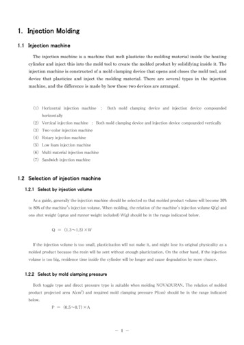
BASTECH ran 75 sets of parts on the Copper Polyamide tools and noticed very little wear. They startedto see a little degradation in a few areas, but could easily have gotten 100 to 150 sets of parts from themolds. The SLS Copper Polyamide tooling withstood an injection molding pressure of 400 psi andinjection molding temperatures of 230 C. They stated that the molds were very sturdy which impressedthem the most. Overall, both BASTECH and there customer were very pleased. The molded parts arepictured in Figure 7 next to one of the mold halves.The SLS Copper Polyamide tooling welloutlasted the AIM tooling. It took an extraday to fit, finish, and polish the SLS tooling;but the resulting tools were more stable, notdeforming during molding, and the partsproduced looked much better. The time andcosts for producing tools using CopperPolyamide in the SLS process or Epoxy in theSLA process are roughly the same.Comparing the timing and costs of an SLSCopper Polyamide tool to that of aconventional steel or machined productiontool offers more compelling numbers. TheSLS molds can be produced at roughly onefourth the cost in only one half the time whencompared to steel tooling. These savings areimportant when only 50 to 500 molded partsare needed.Figure 7. Parts molded by BASTECH in the CopperPolyamide molds pictured next to one of the mold inserts.Case Study #2: Glass guide molded in nylon 6,6 [8]The Rover Group [10], at their Rapid Prototyping and Tooling Department situated on the campus of theUniversity of Warwick, has participated as a beta test site for the Copper Polyamide material. Rover hasstudied, among other things, how tooling made via the SLS process with the new Copper Polyamidematerial compares to alternative low cost tooling routes.One of the parts selected for Rover's comparison was a glass guide (approximately 90 mm x 60 mm x 25mm). This part is used to ensure the automobile door window locates in the rubber seal when closing. Theintended production material was nylon 6,6. They had already created the tool geometry in cast resin, sowhen they created a Copper Polyamide tool with the SLS process it was purely for the sake ofcomparison.Rover designed the single cavity mold inserts as solid objects on a CATIA workstation. The STL fileswere then shelled to a wall thickness of 2.5-mm using Materialise Magic RP software. The inserts wereproduced in one of Rover's two in-house Sinterstation 2500 systems. Once removed from theSinterstation, the hollow tool inserts were backed with an epoxy resin loaded with aluminum powder andgranules. The tool was subsequently machined to fit one of Rover's standard injection molding bolstersets.To trial the Copper Polyamide mold inserts and to ensure the tool was working properly, Rover shot aninitial run of 33 polypropylene parts. Once confident that the tool was working properly, they shot another456
117 nylon 6,6 parts into the Copper Polyamidetool. Nylon 6,6 parts molded in the CopperPolyamide tool are pictured in Figure 8.Rover was pleasantly surprised with theresults. They had not expected the CopperPolyamide tooling to withstand the highinjection temperature of nylon 6,6 which is285 C.Some minor degradation of theCopper Polyamide tool began to occur after 20shots. The degradation was most noticeablearound the sprue puller where the sharp edgesbegan to erode. This area was directly acrossfrom the injection sprue where the moldreaches the highest temperatures. Dr. Illstonat Rover stated that the degradation of the toolwas also exaggerated because the partPolyamide tool. 117 parts molded.geometry was an early prototype design. Theglass guide part featured a section of approximately 1 cm 3 that retained considerable heat during injectionmolding. Increased localized heat build up resulted in additional erosion of the male part geometry wherethe small radii were intended.The final result ofthis project was that 60 nylon glass guides made from the Copper Polyamide tools havebeen installed on Rover Group's prototype vehicles. Under the circumstances, the performance of thetool was far better than expected.Rover has continued to explore the advantagesof the SLS-generated Copper Polyamidetooling. Another project resulted in 300 partsmolded with 30% talc filled polypropylene.The part is a speaker fret (or speaker cover)which measures 38 mm in diameter andfeatures a complex geometry, see Figure 9.During the production of these parts, the toolshowed no wear or part flashing.Theinjection temperature of the polypropylenematerial was 240 C.Rover has worked with a number of rapidtooling methods. Their view is that theCopper Polyamide mold inserts compare moreFigure 9. Speaker fret parts molded with 30% talc filledfavorably to cast resin tools. Although thepolypropylene. 300 parts molded in the Copper PA tool.performance of the Copper Polyamide tools iscomparable to cast tools because the thermal conductivity of the two material systems are similar, thereare advantages to building the mold inserts directly in the Sinterstation from the CAD data. When askedwhich method is faster, Dr. Illston says it all depends on the data available. If the CAD data is availablefor the mold inserts then the Copper Polyamide route is quicker. If the CAD data is only available for thepart, then it is quicker to create a RP master pattern and cast the resin tool. Rover is currently evaluatingthe cost and time comparisons between the two processes.457
ConclusionThe Copper Polyamide material and the Sinterstation system can rapidly produce limited life prototypemold inserts. Prototype quantities of production-quality molded plastic parts can be manufactured withthese metal-based mold inserts.The important attributes of a short run tool are durability, molding cycle times, and speed. The durabilityof the Copper Polyamide tools is comparable to epoxy/metal tooling and is much better than Direct AIMtools. The molding cycle times for Copper PA are similar to metal tooling. This is important becausecycle times can affect the mechanical properties of the molded parts. Mold inserts are created relativelyquickly with the Copper Polyamide material. Molds can be ready for molding in 5 workdays; thisincludes all processing steps required to move from a STL file to molded parts.Table 2. Copper Polyamide product specificationUNITSASTMTESTMETHODBUILT in Sinterstation@15 anglePHYSICAL PROPERTIES;ity0-792g/cm 3!FLAT3.45THERMAL PROPERTIES,1740-648. ." " PIV.kL.9A? M.P.9.".(§§.p JL . " ." "." "PIV. LJ. :.§?"MP.9.j?.§.4.P.§D.". ". ·0-648. "",,1. "E-1530. . , i176.122123··········· .·.·.····.·.·1·.··.·.1.28 -0.92OSC0.66 - 0.87."".Ib .r.r.D.i:lJ"G.9.Q.g. !.i.y.i.ty. . .".40 to 150 C. . """. p i.fi ."H. 9.L . "40 to 150 C"."." !. . .9." "."." ".G.9. m i. .Q.t.I .E?r.'!.1.9.L p.i:l.Q. .i.9.Q30 to 150 Cm/mrCE-831MPa0-638,'92.6 x 10-6. ····.···.·.·.··,·t.·.MECHANICAL PROPERTIESTensile Strength, ultimate(lb/in2)0-790MPaFlexural Strength, 5% strain(lb/in 2)0-790MPaFlexural Modulus(lb/in 2)0-695(lb/in2)nell di It:",,-Shore0-2240"0"SURFACE FINISH" A.§ . §.Pr.9. . .E?qL.R9.""." 223(445,000)MPaCompressive Strength, 0.2% offset33.6Ef!.l.J J .:.L""."{A L,."". .!.?:.?J?.9.QL" .After Finishinq, RaIJm (IJ in.)5.2 (208)2.5 (88)Data was generated from the testing of SLS parts produced with the Copper PA material under typi al processingconditions. (New material processed with a laser power of 15 watts, .scan spee of 5000 mm/sec, scan spacing of 0.1 mm,and a layer thickness of 0.1 mm in the Sinterstation 2500. Samples Infiltrated with Imprex Superseal)458
1. U.and K. MeAlea, "Selective Laser Sintering of Metal Molds: The RapidTool Process",Solid Freeform Fabrication Symposium Proceedings,University of Texas, Texas, pp. 97-104,1996.2. R. Connelly, "Rapid Tooling for Medical Products UsingKe1tool", Rapid Prototyping andManufacturing Conference, Dearborn, Michigan, pp. 89-99, 1997.3. S. Ashley,Toward Rapid Tooling; Extrude Hone", Mechanical Engineering, 120, [7], pp.65-67, 1998.4. T. Wohlers, Rapid Prototyping & Tooling, State of the Industry, Wohlers Associates, Inc.: FortCollins, Colorado, pp. 71-72, 1997.5. 1. Frados, Plastics Engineering Handbook ofthe Society ofthe Plastics Industry, Inc., 4th edition, VanNostrand Reinhold: New York, pp.131-11976.6. Materialise, 6111 Jackson Road, Ann Arbor, Michigan, 48103, www.materialise.com.7. C. Nelson, "Improvements in SLS Part Accuracy", Solid Freeform Fabrication SymposiumUniversity of Texas, Texas, pp. 159-169, 1995.Proceedings,8.and Rover Share Experiences With New Copper Polyamide", Horizons, A Publication ofDTM Corporation, Austin, Texas, Q3 1998.9. B. Staub, BASTECH Inc., 3541 Stop Eight Road, Dayton, Ohio, 45414, www.bastech.com.10. T. Illston, Rover Group,3rd Floor, The University of Warwick, Coventry, CV4 7AL.459
460
Direct Injection Molding Tooling Inserts from the Process with CopperPolyamide Christian Nelson, Jason Kepler, Rick Booth, Phillip Conner DTM Corporation, Austin, The "RapidTool" Short Run (SR) Tooling Process using the Copper Polyamide material provides a route to mold inserts for injection