Transcription
18-548/15-548 Main Memory Architecture10/19/9813Main MemoryArchitecture18-548/15-548 Memory System ArchitecturePhilip KoopmanOctober 19, 1998Required Reading:Cragon 5.1 - 5.1.5Supplemental Reading: Hennessy & Patterson 5.6IBM App. Note: Understanding DRAMAssignmentsuBy next class read about Main Memory Performance: Cragon 5.1.6 - 5.1.7 Fast DRAM article from EDN (Feb. 1997) Supplemental Reading:– Siewiorek & Koopman 5.2.2uHomework 7 due October 21uLab 4 due October 23uTest #2 Wednesday October 28 Emphasizes material since Test #1 In-class review Monday October 26 Closed book, closed notes; bring erasers, sharpened pencils, calculator1
18-548/15-548 Main Memory Architecture10/19/98Where Are We Now?uWhere we’ve been: Cache memory Tuning for performanceuWhere we’re going for two classes: Main memory architecture & performanceuWhere we’re going next: Vector computing BusesPreviewuDRAM chip operation Constraints on minimum memory size vs. performance improvement techniquesuIncreasing memory bandwidth Burst transfers Interleaved access Some of these techniques help with latency as well2
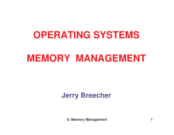
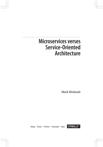
18-548/15-548 Main Memory Architecture10/19/98Main ILEON-CHIPL1 CACHE(?)ON-CHIPL2 CACHEMAINMEMORYCA CH E BYPA SPECIALPURPOSECACHESOTHERCOMPUTERS& WWWUsually Implemented in DRAM3VIRTUALMEMORYDISK FILES &DATABASESCD-ROMTAPEetc.
18-548/15-548 Main Memory Architecture10/19/98Main MemoryuMain Memory is what programmers (think they) manipulate Program space Data space Commonly referred to as “physical memory” (as opposed to “virtual memory”)uTypically constructed from DRAM chips Multiple clock cycles to access data, but may operate in a “burst” mode oncedata access is started Optimized for capacity, not necessarily speeduLatency -- determined by DRAM construction Shared pins for high & low half of address to save on packaging costs Typically 2 or 3 bus cycles to begin accessing data Once access initiated can return multiple data at rate of datum per bus clockMain Memory CapacitiesuMain memory capacity is determined by DRAM chip At least 1 “bank” of DRAM chips is required for minimum memory size(e.g., 4 Mbit chips arranged as 4 bits wide (1 Mbitx4) require 16 chips for a64-bit bus --- 8 Mbyte minimum memory size) Multiple banks (or bigger chips) used to increase memory capacityuBandwidth -- determined by memory word width Memory words typically same width as bus Peak memory bandwidth is usually one word per bus cycle Sustained memory bandwidth varies with the complexity of the design– Sometimes multiple banks can be activated concurrently, exploiting “interleaved”memory Representative main memory bandwidth is 500 MB/sec peak; 125 MB/secsustained4
18-548/15-548 Main Memory Architecture10/19/98DRAM OPERATIONMain Memory DRAM Cells -- Small and Slow5
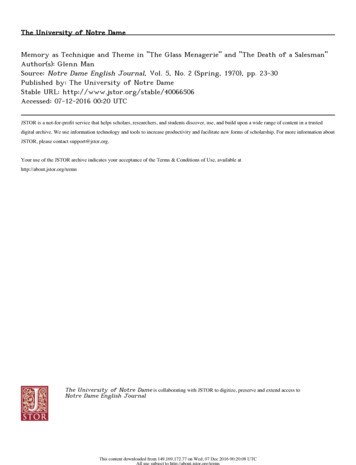
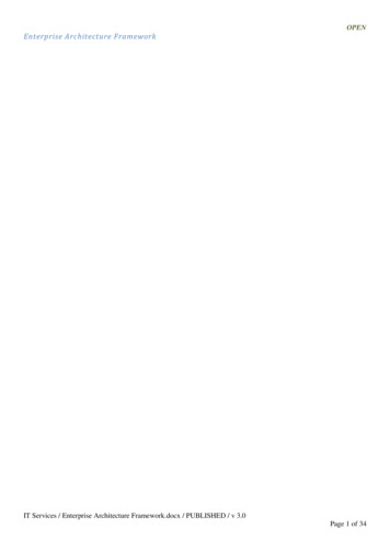
18-548/15-548 Main Memory Architecture10/19/98Micron 64 Mbit DRAMDRAM chip operationuRow Address Select (RAS)RAS#RAS.LCAS#CAS.L Present first half of address to DRAM chip Use to read row from memory arrayuColumn Address Select (CAS) Present second half of address to DRAM chip Use to select bits from row for read/writeuCycle time RAS CAS rewriting data back to arrayuRefresh cycle Access to refresh capacitors Needed every few milliseconds (say, 64 msec); varies with chip6
18-548/15-548 Main Memory Architecture10/19/98DRAM Read Cycle(Micron MT4LC16M4A7)DRAM Write Cycle(Micron MT4LC16M4A7)7
18-548/15-548 Main Memory Architecture10/19/98Main Memory vs. Cache MemoryuCache is optimized for speed On-chip when possible; usually SRAM design If off-chip, single bank of SRAM chips for simplicity & speeduMain memory is optimized for capacity & cost Off-chip; DRAM design Multiple banks of DRAM for capacity, introduces issues of:– Delays for buffers, chip select, address multiplexing– Delays for backplane if separate memory card is used– Delays for bus arbitration if memory is shared with I/O or multiple CPUsuHigh capacity machines have longer main memory latency Alpha L3 cache is 8 MB . which has lower latency than accessing the 512 MB main memory DRAM Embedded system with exactly 1 bank of DRAM can get rid of memory systemoverhead and run faster (but only for small programs)INCREASING DRAM BANDWIDTHPart 1 of 2 -Exotic DRAM componentsare in next lecture8
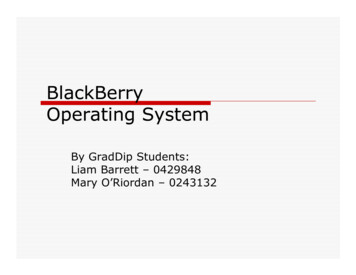
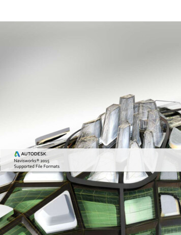
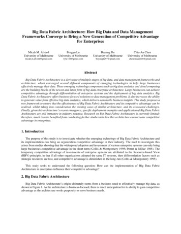
18-548/15-548 Main Memory Architecture10/19/98Exponential Size Growth; Linear SpeedupsDRAM SPEED TRENDS25064 KbitCYCLE TIME (ns)256 Kbit200SLOWEST RAS (nsFASTEST RAS (ns1 MbitCAS (ns)SPEED (ns)4 Mbit15016 Mbit10064 Mbit50019801982198419861988199019921994(Hennessy & Patterson Figure 5.30)YEAR OF INTRODUCTIONConcurrency To Speed Up DRAM AccessesuParallelism: wider paths from cache to DRAM Provides high bandwidth and low latency Increases costuPipelining: pipelined access to DRAM Can provide higher bandwidth with modest latency penalty Often a cost-effective tradeoff, since cache is already helping with latency onmost accessesuReplication: more than one bank of DRAM Can start accessing second DRAM bank while first DRAM bank is refreshingrow Can initiate accesses to many DRAM banks, then read results later9
18-548/15-548 Main Memory Architecture10/19/98Wide Paths to DRAMuLow cost systems reduce board space & package count 32-byte cache block might need 32 DRAM cycles to service a missuWide path to DRAM reduces latency and increases bandwidth Only 1 DRAM cycle to provide full cache line Minimum DRAM configuration might be very large (and expensive)Exploiting DRAM Spatial LocalityuMultiple CAS cycles for single RAS Can access multiple bits from same row without refreshing cells, since all bitsare latched at sense amps Permits slow access to initial word in DRAM, followed by fast access tosubsequent words A good match to servicing cache misses with block size transfer sizeuVarious modes: Nibble mode: DRAM provides several bits sequentially for every RAS Fast Page mode: DRAM row can be randomly addressed with several CAScycles Static column: Same as page mode, but asynchronous CAS access10
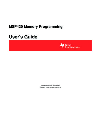
18-548/15-548 Main Memory Architecture10/19/98Fast Page Mode(Micron MT4LC16M4A7)Burst Transfers from DRAMuUse fast page mode, etc., to read several words over a modest widthDRAM bank Can provide higher bandwidth with modest latency penalty Often a cost-effective tradeoff, since cache is already helping with latency onmost accesses11
18-548/15-548 Main Memory Architecture10/19/98Page Mode DRAM Bandwidth ExamplePage Mode DRAM Example:16 bits x 1M DRAM chips in 64-bit module (8 MB module)60 ns RAS CAS access time; 25 ns CAS access time110 ns read/write cycle time; 40 ns page mode access time ; 256 words per pageLatency to first access 60 nsLatency to subsequent accesses 25 nsBandwidth takes into account 110 ns first cycle, 40 ns for CAS cyclesBandwidth for one word 8 bytes / 110 ns 69.35 MB/secBandwidth for two words 16 bytes / (110 40 ns) 101.73 MB/secPeak bandwidth 8 bytes / 40 ns 190.73 MB/secMaximum sustained bandwidth (256 words * 8 bytes) / ( 110ns 256*40ns) 188.71 MB/secCache on a ShoestringuUse page or static column DRAM operation as cache RAS access analogous to “cache miss” that moves data from DRAM array intorow buffer CAS cycles analogous to “cache hit” the provides quick access when spatiallocality is present (i.e., accesses all to single row of DRAM)– Want DRAM controller to keep chip in column access mode unless row addresschanges; a good trick for high-end systems too Acts as a one-block cache of block size DRAM row sizeuAMD 29000 used this technique Targetted for moderately cost-sensitive applications (e.g., laser printers) Used branch instruction buffer to hide RAS latency when taking a branchuKeep in mind for single chip CPU DRAM Wide DRAM row size can be fed to instruction buffer DRAM row can provide wide data input to parallel functional units12
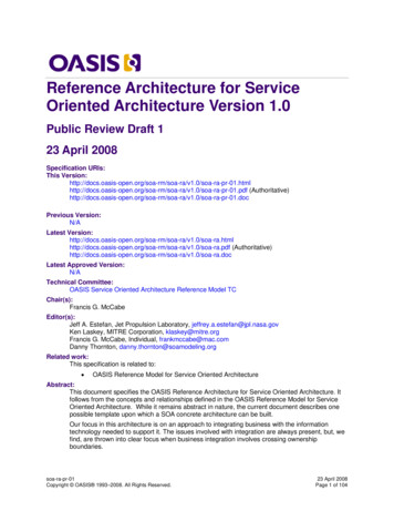
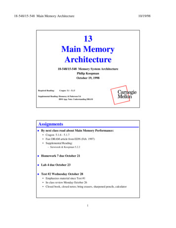
18-548/15-548 Main Memory Architecture10/19/98INTERLEAVED MEMORYMultiple Memory BanksuCan increase available bandwidth Multiple memory banks take turns supplying data -- interleaved access Data can be streamed from memory faster than DRAM cycle timeuCan reduce latency when multiple memory banks are active Multiple banks can be used to hide cycle time Multiple memory references can be serviced concurrentlyuTypically number of banks is a power of 2 for addressing ease Use lowest bits of memory address to select bank Up to 128 banks on supercomputers (Cray 2 and NEC SX/3)(Cragon Figure 5.1)13
18-548/15-548 Main Memory Architecture10/19/98Interleaved Bandwidth IncreaseuBanks take turns supplying data Permits pipelining address and data Equivalent performance to page mode access of DRAM Address x is in bank x MOD b where b is number of banksInterleaved Memory As Dual-Port AlternativeuMultiple independent memory banks have latent bandwidth available Can access m of n single-ported banks simultaneously If m n , chances for bank conflict are reduced If bank conflict occurs, stall one access port (can also simplify data dependencyhandling)uExample: Pentium interleaved data cache(Cragon Figure 5.6)14
18-548/15-548 Main Memory Architecture10/19/98Interleaved Latency Decrease -- cycle timeuMultiple banks hide refresh portion of cycle time For example, ping-ponging between two banks hides end of cycle timeInterleaved Latency Decrease -- concurrencyuMultiple banks service multiple pending memory requests If bus runs faster than DRAM cycles, can have multiple pending memoryrequests– Assumes non-blocking cache or uncached memory accesses Multiple requests can be to arbitrary location; no reliance on spatial locality– Memory requests must be to different banks to prevent conflicts BUT, time to go through interleaving process costs time for a single, isolatedmemory accessDRAM SETINTERLEAVECONTROLLERDRAM SETCPUDRAM SETINTERLEAVECONTROLLERDRAM SET15
18-548/15-548 Main Memory Architecture10/19/98Why Interleaved Memory?uHistorically important on machines that: Didn’t have cache memory Used magnetic core memory instead of DRAM Had multiple CPUs sharing common memoryuBut, becoming prevalent because of generality of the above situations Large gap between CPU-type memory technology and Main Memory-typetechology– Magnetic core instead of transistors– DRAM chips instead of SRAM chips– Off-chip cache instead of on-chip cache Need for high bandwidth in successive accesses having poor spatial locality– Superscalar access to multiple data locations– Multiprocessing accessing shared main memoryPractical Limits -- Minimum Memory SizeuMinimum memory size can be a cost constraint on all but the biggestsystems Assume 64-bit data bus; 64 Mbit DRAMs in 1-bit wide configuration– 64-bit DRAM module will have 64 chips with 512 MB of DRAM Assume 8-way interleaving– Minimum system size is 64 x 8 512 DRAMs 4 GB of DRAM– Memory can only be added in 4 GB chunksuMore importantly (and independent of current technology):minimum # DRAM chips (# memory banks * access width) / DRAM chip widthuCost-effective interleaving solutions Use wide DRAM chips (8-bit wide means 1/8 as many chips as 1-bit wide) Permit smaller interleave factors on low-end machines (expanded memorygives larger interleave factors Use multiple cycles in page mode to retrieve data (Titan trick discussed later)16
18-548/15-548 Main Memory Architecture10/19/98REVIEWReviewuMain memory tradeoffs DRAM optimized for capacity more than for speed Exploit DRAM operation to provide bandwidth (e.g., fast page mode) Minimum possible DRAM size can be a cost constraintuInterleaved memory access Helps with latency by hiding refresh/rewrite time & reducing access conflicts Multiple banks can provide multiple concurrent accesses17
Constraints on minimum memory size vs. performance improvement techniques u Increasing memory bandwidth Burst transfers Interleaved access Some of these techniques help with latency as well. 18-548/15-548 Main Memory Architecture 10/19/98 3 Main Memory REGISTER FI