Transcription
Safe Work PracticesTitle:Reference:Reference:Distribution TransformerInstallation/RemovalSWP 5.14SWP-5.14Page:Date:Revision:1 of 98/27/2018Revised:1.0 PURPOSE1.1 The purpose of this document is to provide guidelines for the installation and removal of the varioustypes of transformers on the Versant Power distribution system.2.0 SAFETY2.1 When working within the “MAD” zone, a yellow tag is required unless the conductors can be properly covered with hard cover and a hot stick.2.2 When work is being performed overhead, employees shall remain away from the base of the pole, exceptto assist the person doing the overhead work.2.3 All equipment and tools to be used aloft shall be raised and lowered by aerial basket, hand line, canvasbucket, or other suitable container. Heavy items shall be raised by crane or hoist. Items should not bethrown or dropped.2.4 Before energy is introduced to any customer on the distribution system, whether that be in the form of single-phase, three-phase, service, secondaries or primaries in a step-down or step-up configuration, voltages andif applicable rotation, shall be verified to ensure the correct application is being delivered to the end-user(s).3.0 GENERAL3.1 The specific procedures for removing or installing pole top transformers are determined by a number of factors, including (1) the type of service (single-phase or three-phase), (2) the rigging and hoisting equipmentto be used, and (3) whether or not service to the customers is to be interrupted during the procedure.3.2 Preparations for a transformer installation/removal job include all of the general precautions for overheadwork. The bucket truck must be parked in a safe location, with wheels chocked and outriggers lowered.Safety cones, flags, signs, and warning lights must be deployed in accordance with the applicable safetyrequirements. It may also be necessary to electrically ground the chassis of the digger/derrick truck, depending upon specific requirements. (Section 3 of the Versant Power Safety Manual)3.3 Specific locations shall be verified ensuring the correct location, pole numbers, circuit and voltages alignwith the service/work order or, in the case of an emergency situation, Atlas, Central Dispatch or the SystemOperator.3.4 Distribution transformers contain various quantities of mineral oil for internal insulation and to remove heatgenerated by electrical losses. If this mineral oil should find its way to wetlands and water sources, such aslakes, streams, wells, or reservoirs, due to a transformer tank failure, a difficult and costly cleanup wouldbe required. (3.4-3.7 VP Standard 2601.1)
Safe Work PracticesTitle:Reference:Reference:Distribution TransformerInstallation/RemovalSWP 5.14SWP-5.14Page:Date:Revision:2 of 98/27/2018Revised:3.5 Therefore, care should be taken when siting transformers around water sources to minimize the possibilityof oil migration to the water if a spill should occur. Whenever possible, transformers should be placed awayfrom water sources, and locations where oil spills could flow to water sources. Secondary cable extensionscan be used to allow moving transformers from potentially sensitive locations, as long as the level of customer load and length of the secondary run is considered to minimize the voltage drop. Transformers thatare required to be installed close to a water source shall be designated "NON-PCB" and have a "NONPCB" label on them.3.6 For proper protection, lightning arrestor leads must be as short and as straight as possible. Primarytaps to CSP transformers must not be coiled. Doing so presents a significantly higher surge impedance toimpulse voltages such as lightning. This increases the effective primary to neutral arrestor clamping voltage.3.7 All high voltage bushings and arresters shall have wildlife guards installed. All transformer and arresterleads shall be covered conductor.4.0 POLE TOP TRANSFORMER REMOVAL4.1 On a conventional transformer installation, the cutout switch will be opened with the correct hot stick.Back-feed checks will be performed on the secondaries by checking for the absence of voltage.4.2 On a CSP transformer using the correct hot stick, the secondary breaker handle will be tripped usually byrotating the handle counter-clockwise and generally in an upward motion, to de-energize the secondarybushings.4.3 Even after the transformer's primary circuit has been opened, it should not be assumed that the transformeris dead. If the secondary bus is still energized from another source, feedback will energize the transformeron both the primary side and the secondary side. Before any circuit can be treated as de-energized, it mustbe tested for voltage.4.4 Best practice is to remove the current carrying leads from the secondary side and then remove the primarytap with the correct hot stick. Once this step has been performed, the transformer cannot be energized fromeither the primary side or the secondary side, even if the cutout switch is accidentally closed.4.5 At this point, the transformer’s case ground connection can be safely removed.5.0 POLE TOP TRANSFORMER INSTALLATION5.1 Proper selection of the correct transformer(s) is critical.
Safe Work PracticesTitle:Reference:Reference:Distribution TransformerInstallation/RemovalSWP 5.14SWP-5.14Page:Date:Revision:3 of 98/27/2018Revised:i. On a pole mounted transformer, the name plate is on or near the lower hanger. Input and output voltages shallbe checked to determine the correct application and once installed, the transformer must be tested and voltageverified to ensure the correct application is being delivered to the end-user(s) before the final connections aremade.ii. Verification of the proper KVA shall be determined from documentation, or in the case of replacement, theline worker may have to use alternative measures. If the transformer is being replaced after hours due to overload, best judgement shall be used to upgrade the KVA for the new install.iii. If the transformer is banked in a three-phase application, polarity and impedance must be considered andmatched with the other transformers in the bank.5.2 If working within the “MAD” zone of the primary conductor(s), a yellow tag must be secured, and the energizedprimary, and if applicable neutral, must be properly covered. A yellow tag is not required if the conductor can beadequately covered with hard guard using a hot line stick.5.3 Following the applicable distribution construction standard (VP Standard 2621) , measure the appropriate distance from the neutral and drill a hole. Measure down from this hole the distance between the hangers or bracket,center to center, and drill the bottom hole.5.4 If a ground rod and down ground aren’t present, they must be installed.5.5 Transformer preparation:i. The first step is to loosen all the bolts on the secondary and primary side of the transformer.ii. Neutral and grounding connections can be installed with soft drawn, stranded copper wire.iii. All connections should be wire brushediv. The appropriate length of “hot” leads shall be installed on the secondary bushing(s).v. The H1 bushing is always the high side lead and a suitable length of stranded copper may be installed.vi. If the transformer being installed is a CSP, open the reset handle.
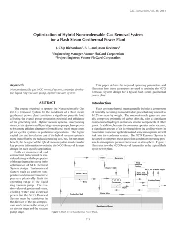
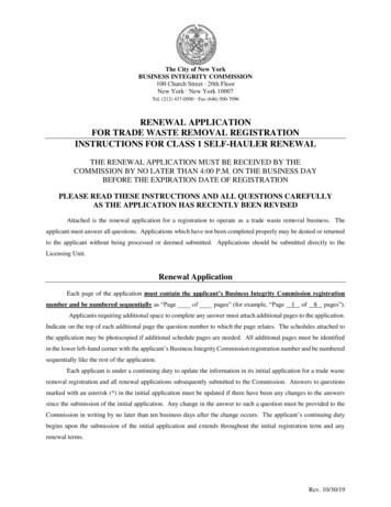
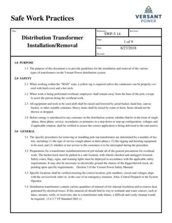
Safe Work PracticesTitle:Reference:Reference:Distribution TransformerInstallation/RemovalSWP 5.14SWP-5.14Page:Date:Revision:4 of 98/27/2018Revised:5.6 Rigging the transformer for installation.i. Below is a typical rigging setup if the pole cannot be reached to set a transformer with the jib.ii. If the bucket can reach the pole and transformer position, the transformer may be installed to thewinch line using this approved sling method:
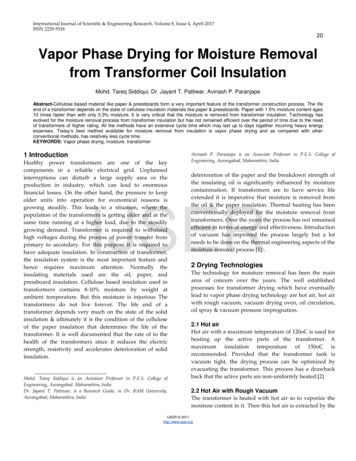
Safe Work PracticesTitle:Reference:Reference:Distribution TransformerInstallation/RemovalSWP 5.14SWP-5.14Page:Date:Revision:5 of 98/27/2018Revised:iii. Aerial device manufactures prohibit the use of wrapping the winch line around a load and hookingback onto itself.5.7 Install (2) machine bolts with washers and locking coils into the predrilled holes, leaving about an inch ofthe bolts protruding from the pole. Lower the transformer onto the bolts and tighten the top bolt first andthen the bottom bolt.5.8 Once the transformer is secure to the pole, the neutral connections are cleaned to ensure good electrical contact. The ground connection provides a low resistance path to ground and prevents the transformer casefrom becoming energized when the primary supply is connected.5.9 The other two secondary connections to the transformer should not be made until transformer voltage has beentested. Isolate the secondary leads and prepare for the voltage test. If all meters are removed that will be fedfrom the transformer, this test may be done at a meter box. The secondary leads can be attached to the service(s). Ensure the meter(s) is removed.5.10 The next step is to make the connections on the primary side of the transformer utilizing a hot stick and hottap. Once the connections are made, energize the transformer by closing the cutout switch on a conventional or closing the handle on a CSP utilizing the correct hot stick.5.11 With the transformer energized, test the secondary voltages and if applicable, rotation. If the connectionswere made with incorrect voltages, customers' equipment could be damaged. If the voltages are correct,the final connections can be made and if applicable, meter set following 5.10 of the VPSM.5.12 After the connections have been made, the transformer is re-energized and tested under load to ensure thatthe voltage is still correct when customers are drawing power. If the voltage readings are correct, the transformer installation procedure is complete. Remove rubber from the overhead lines.
Safe Work PracticesTitle:Reference:Reference:Distribution TransformerInstallation/RemovalSWP 5.14SWP-5.14Page:Date:Revision:6 of 98/27/2018Revised:6.0 PADMOUNT TRANSFORMER REMOVAL6.1 Approaching and Testingi. When approaching any piece of electrical equipment a general site survey should be conducted to identifyall hazards. Identification of these hazards will enable technicians to develop a proper Risk Assessment.Hazards include but are not limited to: Environmental leaks, Physical damage, Electrical exposure, andHousekeeping.ii. Once all of the hazards have been identified a proper Risk Assessment will be completed.ii. There are many tools that can be used in determining the primary and/or secondary voltages of equipment:a. System Diagram/URD 1 Line (Grid, Hardcopies)b. Nameplatec. Cascade Maintenance Database (PST Technician/Supervisor)d. CU Database, AS400 Database (Customer Service)e. GIS/Power On (SO, Central Dispatch, Supervisors, Planners)f. Metering Nameplate or Customer Equipmentg. Atlasiii. Once the voltage rating of the equipment to be approached has been determined, you can refer to the SafetyManual for the proper PPE required. In all cases, Safety Footwear and Safety Glasses must be worn.(VPSM 2.8). Proper ARC rated clothing and equipment (including face shield, balaclava, and leathergloves) shall be determined by referencing the ARC sheet in the Safety Manual, Section 5.3. High Voltagerubber gloves must be worn until the equipment has been verified to be properly grounded (VPSM 5.9.5.3)If secondary voltage cannot be determined ARC 3FB shall be used.iv. After opening a URD enclosure, qualified employee should look for the following hazards, dead end capsin place (BIC), seated elbow, oil leaks, signs of heat or arcing (visual or audible), animal issues, suspectinsulation, proper grounding, loose connectors, cable labels, and verification of expected one line.vi. To properly test equipment for voltage, you should always start on the secondary side using: (listed in order of preferred priority) , before and after testing should be used when possible to verify the presence ofvoltage and the integrity of the test equipment.a. Voltmeter or Multi-meterb. Bierer Voltage tester - Review Bierer Videoc. Salisbury testerd. Permanently connected meteringvii. To properly test equipment for primary voltage, you should use:a. Live Front Pad Mounts and Switchgear - Bierer’s tester or Salisbury Testerb. Dead Front Pad Mounts or Switchgear - Bierer’s Tester or Salisbury Testerc. Dead Front Pad Mounts or Switchgear - Capacitive test points
Safe Work bution TransformerInstallation/RemovalSWP 5.14SWP-5.14Page:Date:7 of 98/27/2018Revised:d. Dead Front Pad Mounts or Switchgear - Permanently wired voltage indication6.2 Installing Groundsi. The various types of grounding equipment that we use (15KV and 34.5KV):a. Cut Out Ground Clampsb. Grounding terminatorsc. Elbow Grounds (Hogan Road Circuits require 2/0 kit from PST)d. 2-Way feed through devices (discuss drain connection)e. 4-Way feed through devices (discuss drain connection)f. Hastings elbow pullerg. Slapstick Pullerh. Bierer HV URD Tester (Video demonstration) (direct contact tester)i. EPZ Matj. Load buster Toolii. Grounding secondaries: There is not a requirement to ground the secondaries of pad mounts or meter enclosures. Methods to protect workers from the low voltage conductors include:a. lock out/ tag out (customer disconnect, transfer switch)b. Isolation/ cover up (remove leads and cover up)c. Isolation/ secure (remove all leads and bolt together)iii. EPZ Mat for equipotential grounding:a. Once the riser pole is grounded at the termination, an EPZ mat is required to be bonded to thegrounding system inside the enclosure.6.3 Once the elbows are pulled, parked on 2-Way feed throughs, tested and grounded, the 2-ways can be removed from thetank and lowered into the vault. The case ground and concentric neutrals may be removed.6.4 The EPZ mat can be disconnected and the transformer rigged for removal.7.0 PADMOUNT TRANSFORMER INSTALLATION7.1 Proper selection of the correct transformer is critical.i. Verify correct KVA size and voltage input/output per Work Orderii. Verify correct location.7.2 Site Preparation (Ref. Distribution Construction Standards 2201-2211.2)i. Before a transformer can be installed, the installation site must be prepared. Site preparation can involve digging cable trenches, installing conduit and cable, and preparing the area where the transformer will sit.ii. The site, vault, trench depth, grounding, and openings must be inspected before a transformer may beInstalled.
Safe Work PracticesTitle:Reference:Reference:Distribution TransformerInstallation/RemovalSWP 5.14SWP-5.14Page:Date:Revision:8 of 98/27/2018Revised:7.3 The transformer is moved into position using a derrick. Proper lifting techniques will be employed, not bolts. Asthe transformer is lowered, it is checked to make sure that it is properly aligned with the pad. After the transformer is in place, the pad is checked again, to ensure that the additional weight of the transformer has notcaused the pad to settle unevenly. Finally, the transformer is anchored to the pad, if necessary.7.4 When all of the equipment is in place, transformer connections are made at three locations: at the connection tothe feeder circuit, at the transformer, and at the customer's connection point.i. First, the transformer case and secondary ground connections are made at the transformer.ii. Verify the status of the secondary cables on the customer’s end and take appropriate precautions to protectthe worker from back feed potential.ii. The secondary connections are made next, if a disconnect is in place so that the voltage (and if applicable,rotation) can be verified before energizing the customer’s facilities. The secondary cable is wire-brushed,to ensure good electrical contact. The secondary cables are often marked to identify their phasing. Markings may be made directly on the cable jacket by the manufacturer, or the phasing may be indicated withcolored tape. It may be necessary, if the transformer turns ratio hasn’t been determined, to energize the transformer before the secondary connections are made to ensure the correct voltage and rotation are in place,before energizing the customer’s equipment. (Ref. Distribution Construction Standard 2213)iii. At the transformer, the primary cable terminations are made with elbows. An elbow is terminated onto eachprimary cable. The primary cable(s) are then installed into the bushing(s) using a slap stick.iv. Terminators can be installed on the riser pole and attached to the primary cutouts and lightening arrestorsfollowing the corresponding distribution standard. (Ref. Distribution Construction Standards 2223-2226)(NOTE: By following these steps in this order, the worker does not have to ground or follow EPZ methods, as thetransformer is not connected to the system and the worker is not exposed to an inadvertent energization. If thetermination on the riser pole is in it’s permanent position, grounding must be followed per VPSM 5.5)8.0 STEP UP/DOWN TRANSFORMER8.1 Proper selection of the correct transformer(s) is critical.i. Verify by the nameplate on the transformer the correct input/output voltages.ii. Labeling may be present on the transformer but can never be solely relied upon for correctly identifyingoutput voltage from the transformer.iii.High and low voltage primary windings are rated phase to ground.iv.Refer to the applicable Versant Power Standards 2601, 2623.1-2623.5.
Safe Work tion TransformerInstallation/RemovalPage:Date:9 of 98/27/2018Revised:v. If the transformer is banked in a three-phase application, polarity and impedance must be considered andmatched with the other transformers in the bank.8.2 Installationi. Install grounds first, remove grounds last.ii. If a ground rod and down ground aren’t present, they must be installed.iii. Ensure that all tank grounds are in place and connected to the neutral.vi. ALWAYS test voltage before delivering to customers.Developed by:T&D PowerSkills; VP Standards; Brian GouldApproved by: SWP CommitteeBrad Flannery, Stan Hartin, Scott Richards, Neil Lyons,Brian Gould
Distribution Transformer Installation/Removal 1.0 PURPOSE 1.1 The purpose of this document is to provide guidelines for the installation and removal of the various types of transformers on the Versant Power distribution system. 2.0 SAFETY 2.1 When working within the “MAD” zone, a yellow