Transcription
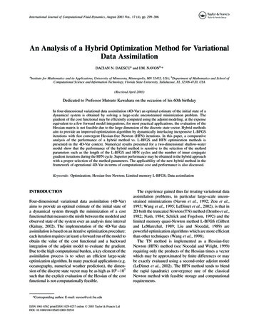
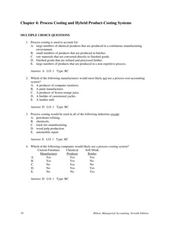
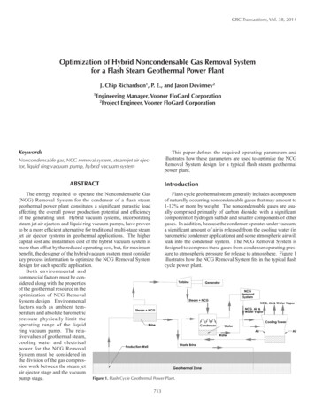
GRC Transactions, Vol. 38, 2014Optimization of Hybrid Noncondensable Gas Removal Systemfor a Flash Steam Geothermal Power PlantJ. Chip Richardson1, P. E., and Jason Devinney21Engineering Manager, Vooner FloGard Corporation2Project Engineer, Vooner FloGard CorporationKeywordsThis paper defines the required operating parameters andillustrates how these parameters are used to optimize the NCGRemoval System design for a typical flash steam geothermalpower plant.Noncondensable gas, NCG removal system, steam jet air ejector, liquid ring vacuum pump, hybrid vacuum systemAbstractIntroductionThe energy required to operate the Noncondensable GasFlash cycle geothermal steam generally includes a component(NCG) Removal System for the condenser of a flash steamof naturally occurring noncondensable gases that may amount togeothermal power plant constitutes a significant parasitic load1-12% or more by weight. The noncondensable gases are usuaffecting the overall power production potential and efficiencyally comprised primarily of carbon dioxide, with a significantof the generating unit. Hybrid vacuum systems, incorporatingcomponent of hydrogen sulfide and smaller components of othersteam jet air ejectors and liquid ring vacuum pumps, have provengases. In addition, because the condenser operates under vacuum,to be a more efficient alternative for traditional multi-stage steama significant amount of air is released from the cooling water (injet air ejector systems in geothermal applications. The higherbarometric condenser applications) and some atmospheric air willcapital cost and installation cost of the hybrid vacuum system isleak into the condenser system. The NCG Removal System ismore than offset by the reduced operating cost, but, for maximumdesigned to compress these gases from condenser operating presbenefit, the designer of the hybrid vacuum system must considersure to atmospheric pressure for release to atmosphere. Figure 1key process information to optimize the NCG Removal Systemillustrates how the NCG Removal System fits in the typical flashdesign for each specific application.cycle power plant.Both environmental andcommercial factors must be considered along with the propertiesof the geothermal resource in theoptimization of NCG RemovalSystem design. Environmentalfactors such as ambient temperature and absolute barometricpressure physically limit theoperating range of the liquidring vacuum pump. The relative values of geothermal steam,cooling water and electricalpower for the NCG RemovalSystem must be considered inthe division of the gas compression work between the steam jetair ejector stage and the vacuumFigure 1. Flash Cycle Geothermal Power Plant.pump stage.713
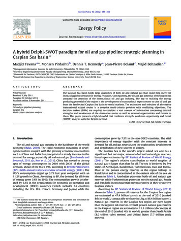
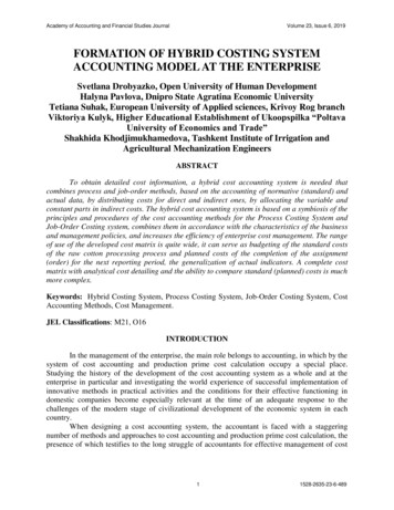
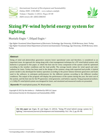
Richardson and DevinneyThe design capacity of the NCG Removal System is the sumof the expected noncondensable gases in the steam reaching thecondenser, the air released by the cooling water (barometric design), the expected air in-leakage and the water vapor requiredto saturate the noncondensable gases at the condenser operatingpressure and vapor temperature. Additional noncondensablegases, from steam jet motive steam, intercondenser cooling waterair release (barometric design), and gland steam condensers areusually introduced into the process.in the suction chamber.”1 Within its design operating range, thesteam jet air ejector is essentially a constant mass flow device.Primary advantages of using steam jet air ejectors include reliability from the simplicity of the design that requires no movingmechanical parts, and the ability perform compression without thenecessity of cooling water. However, cooling is usually employedto improve the efficiency of multi-stage systems.The primary disadvantage of using steam jet air ejectors isthat the thermal efficiency is low in comparison to mechanicalcompression. Although no universally accepted definition of theefficiency of steam jet air ejectors exists, and the efficiency varies widely with compression ratio, the steam and cooling waterrequirements for a particular application can be confidently predicted by the manufacturer. Within the typical temperature andcompression range of a geothermal NCG removal system, theeffective efficiency of the steam jet ranges from 10 to 20 percentand peaks at compression ratios of approximately 4:1.2Steam Jet Air Ejector SystemThe traditional NCG Removal System design, as shown in Figure 2, consists of a multi-stage steam jet air ejector (SJAE) systemwith intercondensers between stages. The Heat Exchange Instituteexplains “The operating principle of a steam jet air ejector stageis that the pressure energy in the motive steam is converted intovelocity energy in the nozzle, and, this high velocity jet of steamentrains the vapor or gas being pumped. The resulting mixture, atthe resulting velocity, enters the diffuser where this velocity energyis converted to pressure energy so that the pressure of the mixtureat the ejector discharge is substantially higher than the pressureLiquid Ring Vacuum Pump BasicsThe Heat Exchange Institute defines a liquid ring vacuumpump as “a specific form of rotary positive displacement pump utilizing liquid as the principal elementin gas compression” and explains that“the compression is performed by theliquid ring as a result of the relativeeccentricity between the casing anda rotating multi-bladed impeller.”3Figure 3 illustrates the operatingprinciple of the liquid ring vacuumpump. Within its design operatingrange, a liquid ring vacuum pumpoperates as a near constant volumedevice and absorbs most of the heatof compression and condensation inthe sealing liquid.Ideal gas laws are used to convertthe mass flow of noncondensablegases and condensable vapors tovolumetric flow at the inlet to thevacuum pump. Vacuum pump powerSTANDARDSOFTHEHEATFigure 2. TwoStageSteamJet AirEXCHANGEEjector System.INSTITUTE, INC.requirements, empirically establishedto Heat Exchange Institute standardsfor dry air performance, must becorrected for the molecular weightof the noncondensable gases and forthe actual compression ratio of theapplication.The primary advantage of usingliquid ring vacuum pumps in lieu ofsteam jet air ejectors is the significantly higher efficiency of compression.Although there is no universallyaccepted definition of efficiency forliquid ring vacuum pumps, and theoverall thermal efficiency dependsgreatly on condensing effects, theFigure 3. Liquid Ring Vacuum Pump (from Heat Exchange Institute Performance Standard for Liquid Ringrelative efficiency of a single stageVacuum Pumps).Figure 2CONICAL PORT7144.2 TypesCommon types of liquid ring vacuum pumps are as follows:
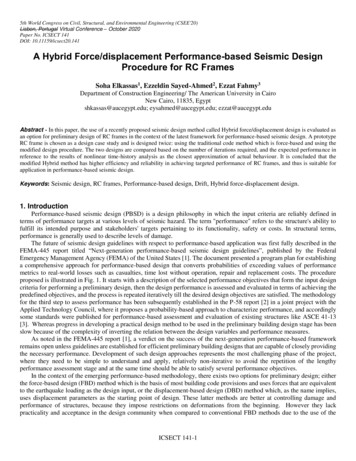
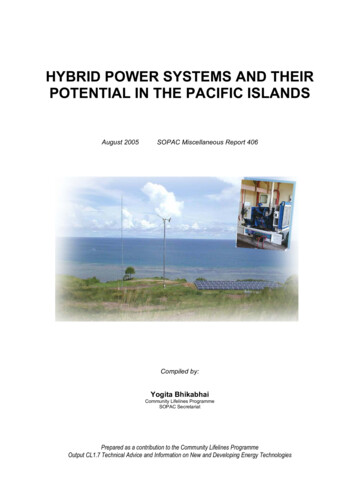
Richardson and Devinneypump is highest over the range of 1.5:1 to 6:1 compression. Efficiency for a particular size of liquid ring vacuum pump, however,varies significantly with the pump operating speed as well ascompression ratio as shown in Figure 4.60.0%the main cooling tower and is drained to the main condenser tobe returned to the cooling tower.The actual configuration of the hybrid NCG removal systemoften consists of multiple parallel partial capacity trains whichmay be used with a common intercondenser. Configuration ofthe system is specified by the user based on confidence in NCGload and requirement for IsothermalEfficiencyOptimization of Hybrid NCG Removal Design50.0%Following is the minimum information required for design ofthe Hybrid NCG Removal System:MinimumpumpOpera ngSpeed1. First stage suction pressure (condenser design operatingpressure minus pressure drop in vapor piping to first stageejector)MaximumPumpOpera ngSpeed40.0%2. Vapor temperature at first stage suction3. Design basis noncondensable gas mass flow rate30.0%2.003.004.005.006.007.004. Design basis noncondensable gas composition or averagemolecular weight8.00CompressionRa oFigure 4.5. Design basis air release from cooling water and in-leakage6. Mass flow of water vapor to saturate noncondensables andair at condenser operating pressure and vapor dischargetemperatureApplication of the liquid ring vacuum pump is limited bythe vapor pressure of the seal water in the vacuum pump whichprecludes use of vacuum pumps for the full compression rangerequired for most geothermal condenser NCG removal systems.7. Design basis motive steam pressure available for steamjet(s)Typical Hybrid Steam Jet/Vacuum Pump System8. NCG content of motive steamFigure 5 illustrates a hybrid NCG Removal System using asteam jet air ejector for the initial stage(s) of compression, with anintercondenser used to minimize the condensable vapor load to theliquid ring vacuum pump performing the final stage of compression. The system requires steam for the ejector(s), cooling waterfor the intercondenser and vacuum pump and electrical power forthe vacuum pump. The cooling water is usually furnished from10. Discharge pressure of the system (average absolute atmospheric pressure plus any pressure required for dischargevapor piping or processing)9. Design basis cooling water supply temperature and pressureOptimization of the Hybrid NCG Removal System design is aniterative process that begins withselection of the lowest interstagepressure that allows the vacuumpump to operate efficiently withconsideration of the requiredcompression ratio, available cooling water temperature and thecondensation and compressionheat load to determine the expected operating temperature ofthe liquid ring. The preliminaryvolumetric capacity required forthe vacuum pump must includesome allowance for additionalNCG from motive steam andother sources. Because liquidring vacuum pump efficiencydecreases with increasing operating speed, optimization of thesystem design usually favors alarger vacuum pump selectionFigure 5. Hybrid NCG Removal System.715
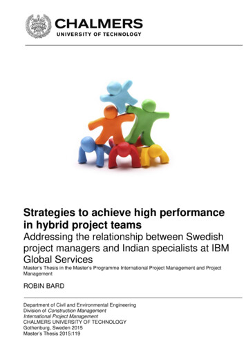
Richardson and Devinneywith slower operating speed over a smaller pump operating ahigher speed for the same capacity.The optimization process involves iteratively completing amass flow and heat balance, beginning with an estimated intercondenser operating pressure and vapor temperature, as shownin Figure 6.CoolingWater?M3/HR Water?KG/HR Water?KG/HR AirDesign BARADesign CFIRSTSTAGESJAE?FromSJAEKG/HR NCGKG/HR WVKG/HR AirBARA CFromCondenserDesign KG/HR NCGDesign KG/HR WVDesign KG/HR AirDesign BARADesign CINTERCONDENSER?BARA? C?IntercondenserDrain?M3/HR Water?KG/HR Water?BARA? C?Figure 6. Mass and Heat Balance for Hybrid Vacuum System. CActual Project ExamplesDesigning the intercondenser for the lowest practical approach temperature is important to minimize the volumetric loadto the vacuum pump by minimizing the partial volume occupiedby saturation water vapor. Although some water vapor can becondensed with spray nozzles installed in the vacuum pump inletmanifold, the saturation water vapor from the intercondenser ismore efficiently liquefied by direct condensing than by condensingby compression in the vacuum pump.Next, the steam jet air ejector(s) must be designed to compressthe design vapor load to the vacuum pump suction pressure,accounting for pressure drop through the intercondenser and associated vapor piping. When the ejector motive steam requirementis determined, the extra NCG load is calculated, and the vacuumpump operating conditions are adjusted if necessary.The result is a system designed to perform as much of thecompression work as possible using the most efficient device.Figure 7 illustrates the evaluation of a range of potentialintercondenser pressures for a particular geothermal project,presenting the kilowatt equivalent auxiliary loads as a percentageof design 0%5.00%4.00%3.00%AUXLOAD/NETKWMotiveSteam?KG/HR WV?KG/HR NCGDesign BARADesign Cdenser and vacuum pump cooling water requirement may beapproximately 1,000 M3/HR and require approximately 15 KWto pump the cooling water from the cooling tower to the NCGsystem and from the condenser to the cooling tower. The secondstage vacuum pump may require 500 KW for a total equivalentpower requirement of 1,500 15 500 2,015 KW equivalenttotal auxiliary load.For comparative purposes, a further step inSealWater?M3/HR Waterthe cost evaluation is to?KG/HR Waterdetermine the auxiliaryDesign BARADesign Cpower cost per kilogramof NCG to be removed.In the above example, ifFromICKG/HR NCGthe NCG content of theKG/HR WVLIQUIDRINGsteam is 2% by weight,KG/HR AirVACUUMPUMPBARA300,000 X 0.02 6,000 CKG/HR of NCG mustbe removed and theFromLRVPpower requirement is?KG/HR NCG2,015/6,000 0.34 KW/?KG/HR WV(KG/HR) NCG or 0.34?KG/HR AirDesign BARAKW-HR/KG NCG.2.00%LRVPAuxKWEvaluation of the Operating Costof the NCG SUREBARAA simple method of evaluating the operating cost of the NCGSystem is to value the ejector motive steam requirement, the cooling water pumping requirement and the liquid ring vacuum pumppower requirement as equivalent to electrical power producedby the geothermal power plant. For example, if a 50MW netoutput facility requires 300,000 KG/HR of geothermal steam inthe turbine, each KW of output requires 300,000/50,000 6 KG/HR of steam.In this example, the NCG system first stage steam jet airejector facility may require 9,000 KG/HR of motive steam,equivalent to 9,000/6 1,500 KW of power. The intercon-Figure 7. Optimization of NCG Removal System Design.In this example, the power requirement of the NCG RemovalSystem is reduced by approximately 2% of total output as thedesign interstage pressure is lowered from approximately 0.35barA to approximately 0.30 barA. If this were a 50 MW plant,the difference in equivalent auxiliary power requirement wouldbe approximately 1 MW, corresponding to a reduction in operating cost of approximately 420,000 per year based on a value of 0.05/KW-HR. Continuing to reduce the interstage pressure from716
Richardson and Devinney0.30 barA to 0.20 barA results in an additional reduction of 1.7%of total output corresponding to
ring vacuum pump. The rela-tive values of geothermal steam, cooling water and electrical power for the NCG Removal System must be considered in the division of the gas compres-sion work between the steam jet air ejector stage and the vacuum pump stage.