Transcription
EE 740Power TransformersY. BaghzouzSpring 2013
Preliminary considerationsA transformer is a device that converts one AC voltage toanother AC voltage at the same frequency. It consists of oneor more coil(s) of wire wrapped around a commonferromagnetic core. In practice, the windings are wrapped on top ofeach other to minimize flux leakage.
Ideal transformerAn ideal transformer (unlike the real one) can be characterized asfollows:1.The core has no hysteresis nor eddy currents.2.The magnetization curve is vertical with no saturation3.The leakage flux in the core is zero.4.The resistance of the windings is zero.Consider a lossless transformer with an input (primary) windinghaving Np turns and an output (secondary) winding of Ns turns.The relationship between the voltage applied to the primary windingvp(t) and the voltage produced on the secondary winding vs(t) isv p (t )vs (t ) NpNs awhere a is the turn ratio of the transformer.
Ideal transformerThe relationship between the primary ip(t) and secondary is(t) currents isi p (t )1 is (t ) aPhasor notation:VpVs aIpIs 1a The phase angles of primary and secondary voltages are the same. The phase angles of primary and secondary currents are the same also. The ideal transformer changes magnitudes of voltages and currents but nottheir angles.
Ideal Transformer One winding’s terminal is usually marked by a dot used todetermine the polarity of voltages and currents. If the voltage is positive at the dotted end of the primarywinding at some moment of time, the voltage at the dotted endof the secondary winding will also be positive at the same timeinstance. If the primary current flows into the dotted end of the primarywinding, the secondary current will flow out of the dotted endof the secondary winding.
Power in an ideal transformerAssuming that p and s are the angles between voltages and currents on theprimary and secondary windings respectively, the power supplied to thetransformer by the primary circuit is:Pin Vp I p cos pThe power supplied to the output circuit isPout Vs I s cos sSince ideal transformers do not affect angles between voltages and currents: p s
Power in an ideal transformerSince for an ideal transformer the following holds:Vs Vpa; I s aI pTherefore:Pout Vs I s cos VpaaI p cos Vp I p cos PinThe output power of an ideal transformer equals to its input power – to beexpected since assumed no loss. Similarly, for reactive and apparent powers:Qout Vs I s sin Vp I p sin QinSout Vs I s Vp I p Sin
Impedance transformationThe impedance is defined as a following ratio of phasors:Z L VL I LA transformer changes voltages and currents and, therefore, an apparentimpedance of the load that is given byZ L Vs I sThe apparent impedance of theprimary circuit is:Z L ' Vp I pwhich isVpaVs2 VsZL ' a a2 ZLI p Is aIs
Analysis of circuits containing ideal transformers:ExampleExample 4.1: a) What is the voltage at the load? Calculate the transmission linelosses? b) If a 1:10 step up transformer and a 10:1 step down transformer areplaced at the generator and the load ends of the transmission line respectively,what are the new load voltage and the new transmission line losses?a) Without transformers:I G I line I load VZline Zload480 0 0.18 j 0.24 4 j 3480 0 90.8 37.8 A5.29 37.8 Vload Iload Zload 90.8 37.8 (4 j3) 90.8 37.8 5 36.9 454 0.9 V2Ploss IlineRline 90.82 0.18 1484 W
Analysis of circuits containing ideal transformers:Exampleb) With transformers, we will eliminate transformer T2by referring the load overto the transmission line’svoltage level. Eliminate transformer T1by referring thetransmission line’s voltagelevel to the source side,IG V480 0 Z'eq 5.003 36.88 95.94 36.88 A
Analysis of circuits containing ideal transformers:ExampleKnowing transformers’ turn ratios, we can determine line and load currents:Iline a1IG 0.1 95.94 36.88 9.594 36.88 AIload a2Iline 10 9.594 36.88 95.94 36.88 ATherefore, the load voltage is:Vload Iload Zload 95.94 36.88 5 36.87 479.7 0.01 VThe losses in the line are:2Ploss IlineRline 9.5942 0.18 16.7 W
Real transformerFlux leakageA portion of the flux produced inthe primary coil passes throughthe secondary coil (mutual flux);the rest passes through theexternal medium (leakage flux): p m Lpmutual fluxleakage primary fluxSimilarly, for the secondary coil: s m LsLeakage secondary flux
Real transformerFrom the Faraday’s law, the primary coil’s voltage is:v p (t ) N pd pd Lpd m Np Np e p (t ) eLp (t )dtdtdtThe secondary coil’s voltage is:d sd md Lsvs (t ) N s Ns Ns es (t ) eLs (t )dtdtdtThe primary and secondary voltages due to the mutual flux are:d me p (t ) N pdtd Lses (t ) N sdtCombining the last two equations:e p (t )Npd m es (t ) dtNs
Real transformerTherefore:e p (t )es (t ) NpNs aThat is, the ratio of the primary voltage to the secondary voltage both caused bythe mutual flux is equal to the turns ratio of the transformer.The following approximation normally holds since the leakage flux is muchsmaller than the mutual flux;:v p (t )vs (t ) NpNs a
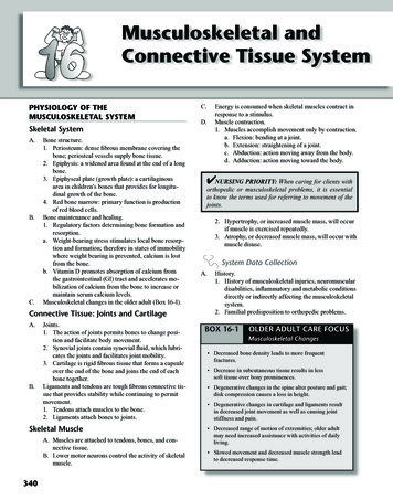
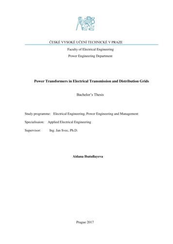
The magnetization current in a real transformerEven when no load is connected to the secondary coil of the transformer, acurrent will flow in the primary coil. This current consists of:1. The magnetization current im is needed to produce the flux in the core;2. The core-loss current ih e corresponds to hysteresis and eddy currentlosses.Flux causing themagnetization currentTypical magnetization curve
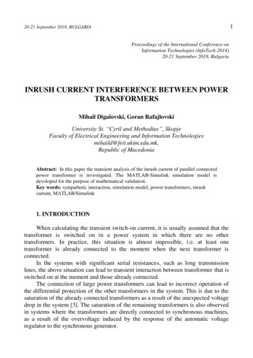
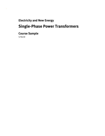
Excitation Current in a real transformertotal excitation current in a transformerCore-loss currentCore-loss current is:1. Nonlinear due to nonlinear effects of hysteresis;2. In phase with the voltage.The total no-load current in the core is called the excitation current ofthe transformer:iex im ih e
The current ratio on a transformerIf a load is connected to the secondary coil, there will be a current flowingthrough it.A current flowing into the dottedend of a winding produces apositive magnetomotive force F:Fp N pi pFs N s isThe net magnetomotive force in thecore isFnet N pi p N sis For well-designed transformer cores, the reluctance is very small if thecore is not saturated. Therefore:Fnet N pi p N sis 0ipNs 1N p i p N s is is N p a
The transformer’s equivalent circuitTo model a real transformer accurately, we need to account forthe following losses:1. Copper losses – resistive heating in the windings: I2R.2. Eddy current losses – resistive heating in the core:proportional to the square of voltage applied to thetransformer.3. Hysteresis losses – energy needed to rearrange magneticdomains in the core: nonlinear function of the voltageapplied to the transformer.4. Leakage flux – flux that escapes from the core and flux thatpasses through one winding only.
The exact equivalent circuit of a real transformer Cooper losses are modeled by the resistors Rp and Rs. The leakage flux can be modeled by primary and secondary inductors. The magnetization current can be modeled by a reactance XMconnected across the primary voltage source. The core-loss current can be modeled by a resistance RC connectedacross the primary voltage source. Both magnetizing and core loss currents are nonlinear; therefore, XMand RC are just approximations.
The exact equivalent circuit of a real transformerThe equivalent circuit is usually referred to the primary sideor the secondary side of the transformer.Equivalent circuit of thetransformer referred to itsprimary side.Equivalent circuit of thetransformer referred to itssecondary side.
Approximate equivalent circuit of a transformerReferred to the primary side.Without an excitation branchreferred to the primary side.Referred to the secondary side.Without an excitation branchreferred to the secondary side.
Determining the values of componentsThe open-circuit test.Full line voltage is applied to the primaryside of the transformer. The input voltage,current, and power are measured.From this information, the power factor of the input current and the magnitude andthe angle of the excitation impedance can be determined.To evaluate RC and XM, we define the conductance of the core-loss resistance andThe susceptance of the magnetizing inductor :GC 1RC1BM XM
Determining the values of componentsSince both elements are in parallel, their admittances add. Therefore, the totalexcitation admittance is:YE GC jBM 11 jRCXMThe magnitude of the excitation admittance in the open-circuit test is:I ocYE VocThe angle of the admittance in the open-circuit test can be found from the circuitpower factor (PF):Poccos PF Voc I oc
Determining the values of componentsIn real transformers, the power factor is always lagging, so the angle of the currentalways lags the angle of the voltage by degrees. The admittance is:I ocI ocYE cos 1 PFVocVocTherefore, it is possible to determine values of RC and XM in the open-circuit test.
Determining the values of componentsThe short-circuit test:.Fairly low input voltage is applied to theprimary side of the transformer. This voltageis adjusted until the current in the secondarywinding equals to its rated value.The input voltage, current, and power are measured.Since the input voltage is low, the current flowing through the excitation branch isnegligible; therefore, all the voltage drop in the transformer is due to the serieselements in the circuit. The magnitude of the series impedance referred to theprimary side of the transformer is:Z SE VSCI SCThe power factor of the current is given by:PSCPF cos VSC I SC
Determining the values of componentsTherefore:Z SE VSC 0 VSC I SC I SCSince the serial impedance ZSE is equal toZ SE Req jX eqZ SE Rp a 2 RS j X p a 2 X S The same tests can be performed on the secondary side of the transformer. Theresults will yield the equivalent circuit impedances referred to the secondaryside of the transformer.
ExampleExample 4.2: We need to determine the equivalent circuit impedances of a 20kVA, 8000/240 V, 60 Hz transformer. The open-circuit and short-circuit tests led tothe following data:RC VOC 8000 VVSC 489 VIOC 0.214 AISC 2.5 APOC 400 WPSC 240 W11 159 k ; X M 38.3 k 0.00000630.0000261Req 38.3 ; X eq 192
The per-unit system1. Note that the apparent power rating (base) of a transformer isthe same for both the primary and secondary sides.2. On the other hand, the voltage rating (base) changesaccording to its turn ratio.3. The impedance of the transformer is often given in pu.Example: a 110/440 V, 2.5 kVA transformer has a leakagereactance of 1.24% (or 0.0124 pu). Determine the Ohmicvalue when referred to the low-voltage side:Ans. 60 mΩ.
The per-unit system: ExampleExample 4.4: Sketch the appropriate per-unit equivalent circuit for a8000/240 V, 60 Hz, 20 kVA transformer with Rc 159 k , XM 38.4 k , Req 38.3 , Xeq 192 . All the impedance values are referred to the primarysideTo convert the transformer to per-unit system, the primary circuit baseimpedance needs to be found.Vbase 1 8 000 V ; Sbase 1 20 000 VA2Vbase8 0002 1Z base 1 3 200 Sbase 1 20 00038.4 j192Z SE , pu 0.012 j 0.06 pu3 200159 000RC , pu 49.7 pu3 200 00X M , pu 12 pu3 200
Voltage Regulation (VR)Since a real transformer contains series impedances, the transformer’soutput voltage varies with the load even if the input voltage is constant.To compare transformers in this respect, the quantity called a full-loadvoltage regulation (VR) is defined as follows:VR Vs ,nl Vs , flVs , fl 100% Vp a Vs , flVs , fl 100%In a per-unit system:VR Vp , pu Vs , fl , puVs , fl , pu 100%Where Vs,nl and Vs,fl are the secondary no load and full load voltages.Note: the VR of an ideal transformer is zero under any load condition.
Transformer phasor diagramTo determine the VR of a transformer, it is necessary to understand the voltagedrops within it. Usually, the effects of the excitation branch on transformer VR canbe ignored and, therefore, only the series impedances need to be considered. TheVR depends on the magnitude of the impedances and on the current phase angle.A phasor diagram is often used in the VR determinations. The phasor voltage Vs isassumed to be at 00 and all other voltages and currents are compared to it.Considering the diagram and by applying theKirchhoff’s voltage law, the primary voltage is:Vpa Vs Req I s jX eq I sA transformer phasor diagram is a graphicalrepresentation of this equation.
Transformer phasor diagramA transformer operating at a lagging power factor:It is seen that Vp/a Vs, VR 0A transformer operating ata unity power factor:It is seen that VR 0A transformer operating at aleading power factor:If the secondary current is leading,the secondary voltage can be higherthan the referred primary voltage;VR 0.
Transformer efficiencyThe efficiency of a transformer is defined as: PoutPout 100% 100%PinPout PlossNote: the same equation describes the efficiency of motors and generators.Considering the transformer equivalent circuit, we notice three types of losses:1. Copper (I2R) losses – are accounted for by the series resistance2. Hysteresis and eddy current losses – are accounted for by the resistor Rc.Since the output power isThe transformer efficiency isPout Vs I s cos sVs I s cos 100%PCu Pcore Vs I s cos
The transformer efficiency: ExampleExample 4.5: A 15 kVA, 2300/230 V transformer was tested to by open-circuit andclosed-circuit tests. The following data was obtained:VOC 2300 VVSC 47 VIOC 0.21 AISC 6.0 APOC 50 WPSC 160 Wa) Find the equivalent circuit of this transformer referred to the high-voltage side.b) Find the equivalent circuit of this transformer referred to the low-voltage side.c) Calculate the full-load voltage regulation at 0.8 lagging power factor, at 1.0power factor, and at 0.8 leading power factor.d) Plot the voltage regulation as load is increased from no load to full load atpower factors of 0.8 lagging, 1.0, and 0.8 leading.e) What is the efficiency of the transformer at full load with a power factor of 0.8lagging?
The transformer efficiency: Example Pout 100% 98.03%PCu Pcore Pout
Transformer taps and voltage regulationWe assumed before that the transformer turns ratio is a fixed (constant)for the given transformer. Frequently, distribution transformers have aseries of taps in the windings to permit small changes in their turns ratio.Typically, transformers may have 4 taps in addition to the nominal settingwith spacing of 2.5 % of full-load voltage. Therefore, adjustments up to 5% above or below the nominal voltage rating of the transformer arepossible.Example 4.6: A 500 kVA, 13 200/480 V transformer has four 2.5 % tapson its primary winding. What are the transformer’s voltage ratios at eachtap setting?Ans: 5.0% tap 2.5% tapNominal rating- 2.5% tap- 5.0% tap13 860/480 V13 530/480 V13 200/480 V12 870/480 V12 540/480 V
Transformer taps and voltage regulation Taps allow adjustment of the transformer in the field toaccommodate for local voltage variations.Sometimes, transformers are used on a power line, whosevoltage varies widely with the load (due to high line impedance,for instance). Normal loads need fairly constant input voltagethoughOne possible solution to this problem is to use a specialtransformer called a tap changing under load (TCUL)transformer or voltage regulator. TCUL is a transformer with theability to change taps while power is connected to it. A voltageregulator is a TCUL with build-in voltage sensing circuitry thatautomatically changes taps to keep the system voltageconstant.These “self-adjusting” transformers are very common inmodern power systems.
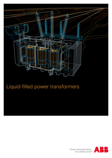
The autotransformerSometimes, it is desirable to change the voltage by a small amount (forinstance, when the consumer is far away from the generator and it isneeded to raise the voltage to compensate for voltage drops).In such situations, it would be expensive to wind a transformer with twowindings of approximately equal number of turns. An autotransformer (atransformer with only one winding) is used instead.Diagrams of step-up and step-down indingCommonwindingOutput (up) or input (down) voltage is a sum of voltages across common and series windings.
The autotransformerSince the autotransformer’s coils are physically connected, a differentterminology is used for autotransformers:The voltage across the common winding is called a common voltage VC,and the current through this coil is called a common current IC. The voltageacross the series winding is called a series voltage VSE, and the currentthrough that coil is called a series current ISE.The voltage and current on the low-voltage side are called VL and IL; thevoltage and current on the high-voltage side are called VH and IH.For the autotransformers:VCNC VSE N SENC IC N SE I SENCVL VH NC N SEI L NC N SE IHNC
The apparent power advantageThe ratio of the apparent power in the primary and secondary of theautotransformer to the apparent power actually traveling through itswindings isS IO N SE NC SWN SEThe last equation described the apparent power rating advantage ofan autotransformer over a conventional transformer.SW is the apparent power actually passing through the windings. The restpasses from primary to secondary parts without being coupled through thewindings.Note that the smaller the series winding, the greater the advantage!
The apparent power advantageFor example, a 5 MVA autotransformer that connects a 110 kV system to a138 kV system would have a turns ratio (common to series) 110:28. Suchan autotransformer would actually have windings rated at:SW S ION SE28 5 1.015 MVAN SE NC28 110Therefore, the autotransformer would have windings rated at slightly over 1MVA instead of 5 MVA, which makes is 5 times smaller and, therefore,considerably less expensive.However, the construction of autotransformers is usually slightly different.In particular, the insulation on the smaller coil (the series winding) of theautotransformer is made as strong as the insulation on the larger coil towithstand the full output voltage.The primary disadvantage of an autotransformer is that there is a directphysical connection between its primary and secondary circuits. Therefore,the electrical isolation of two sides is lost.
3-phase transformersThe majority of the power generation/distribution systems in the world are 3phase systems. The transformers for such circuits can be constructed eitheras a 3-phase bank of independent identical transformers (can be replacedindependently) or as a single transformer wound on a single 3-legged core(lighter, cheaper, more efficient).
3-phase transformer connectionsWe assume that any single transformer in a 3-phase transformer (bank)behaves exactly as a single-phase transformer. The impedance, voltageregulation, efficiency, and other calculations for 3-phase transformers aredone on a per-phase basis, using the techniques studied previously forsingle-phase transformers.Four possible connections for a 3-phase transformer bank are:1. Y-Y2. Y- 3. - 4. -Y
3-phase transformer connections1. Y-Y connection:The primary voltage on each phase ofthe transformer isVLPV P 3The secondary phase voltage isVLS 3V SThe overall voltage ratio is3V PVLP aVLS3V S
3-phase transformer connections4. - connection:The primary voltage on each phase ofthe transformer isV P VLPThe secondary phase voltage isVLS V SThe overall voltage ratio isVLP V P aVLS V SNo phase shift, no problems withunbalanced loads or harmonics.
3-phase transformer connections3. -Y connection:The primary voltage on each phase ofthe transformer isV P VLPThe secondary phase voltage isVLS 3V SThe overall voltage ratio isV PVLPa VLS3V S3The same advantages and the samephase shift as the Y- connection.
Transferring Ohmic Values of Per-Phase Impedances
Phase Shifts and Equivalent Circuits When stepping up the voltage in a Y-Δ or Δ-Y transformer, thepositive sequence voltages and currents are advanced by 30o.
Per-Unit Impedances in 3-Winding TransformerFictitiousneutral pointZp, Zs, and Zt, are the impedances of the primary, secondary, and tertiarywindings, respectively, referred to the primary circuit. if Zps, Zpt, and Zst, arethe measured impedances referred to the primary circuit, then
Regulating Transformers for Control of Voltage Magnitudeand PhaseControl of Voltage MagnitudeControl of Voltage Phase Angle
Example (refer to book)Case 0: Two parallel transformers with the sameturn ratio and same rating. the transformersshare the load equallyCase 1: Tb is providing a voltage ratio 5% higherthan Ta. The transformer with the higher tapsetting is supplying most of the reactive power tothe load.Case 2: Tb is a regulating transformer with aphase shift of 3o. The phase shifting transformeris supplying most of the real power to the load.
Transformers Operating in Parallel Example: a 100 kVA transformer (with X 4%) is connected in parallel withan existing 250 kVA transformer (with X 6%). The transformers are rated at7200V/240V, and they supply a load of 330 kVA at nominal voltage.Calculate the following:1.2.3.4.5.The nominal secondary current of each transformer: (Ans. 416.7 A and1,041A)The current and impedance of the load (Ans. 1,375 A and 174.5 mΩ)The impedance of each transformer when referred to the secondary side: (Ans.23 mΩ and 13.8 mΩ)The current flow through each transformer secondary winding (Ans. 515.6Aand 859.4)Which transformer, if any, is overloaded? (Ans. The smaller transformer iscarrying 124 kVA – nearly a 25% overload!)
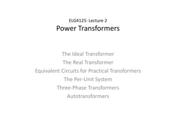
Transformer ratings: Voltage and FrequencyThe voltage rating is a) used to protect the winding insulation from breakdown;b) related to the magnetization current of the transformer (more important)If a steady-state voltagefluxv(t ) VM sin tis applied to the transformer’sprimary winding, the transformer’sflux will be (t ) VM1v(t)dt cos tNp N pAn increase in voltage will lead to aproportional increase in flux.However, after some point (in asaturation region), such increase influx would require an unacceptableincrease in magnetization current!Magnetizationcurrent
Transformer ratings: Voltage and FrequencyTherefore, the maximum applied voltage (and thus the rated voltage) is set bythe maximum acceptable magnetization current in the core.We notice that the maximum flux is also related to the frequency: maxVmax N pTherefore, to maintain the same maximum flux, a change in frequency (say, 50Hz instead of 60 Hz) must be accompanied by the corresponding correction inthe maximum allowed voltage. This reduction in applied voltage with frequencyis called derating. As a result, a 50 Hz transformer may be operated at a 20%higher voltage on 60 Hz if this would not cause insulation damage.
Transformer ratings: Apparent PowerThe apparent power rating sets (together with the voltage rating) thecurrent through the windings. The current determines the i2R losses and,therefore, the heating of the coils.Overheating shortens the life of transformer’s insulation. Under anycircumstances, the temperature of the windings must be limited.A typical power transformer rating would be OA/FA/FOA where The OA (open-air) rating is the base power rating. The FA (forced-air) rating is the power carrying capability whenforced air cooling (fans) are used. The FOA (forced-oil-air) rating is the power carrying capability whenforced air cooling (fans) are used in addition to oil circulating pumps.Each cooling method provides nearly an additional 1/3 capability. Forexample, a common substation transformer is rated at 21/28/35 MVA.
Transformer ratings: Current inrushAssuming that the following voltage is applied to the transformer at the momentit is connected to the line:v(t ) VM sin t The maximum flux reached on the first half-cycle depends on the phase of thevoltage at the instant the voltage is applied. If the initial voltage isv(t ) VM sin t 90 VM cos tand the initial flux in the core is zero, the maximum flux during the first half-cycleis equals to the maximum steady-state flux (which is ok): max VM N pHowever, if the voltage’s initial phase is zero, i.e.v(t ) VM sin t
Transformer ratings: Current inrushthe maximum flux during the first half-cycle will be max 1Np VM sin t dt 0VMcos t N pWhich is twice higher than a normal steady-state flux!Doubling the maximum flux in the corecan bring the core in a saturation and,therefore, may result in a hugemagnetization current!Normally, the voltage phase angle cannotbe controlled. As a result, a large inrushcurrent is possible during the first severalcycles after the transformer is turned ON.The transformer and the power systemmust be able to handle these currents. 02VM N p
Practice Problems (Chap. 2)6, 8, 13, 15, 19, 21, 23.
The output power of an ideal transformer equals to its input power – to be expected since assumed no loss. Similarly, for reactive and apparent powers: Q n nTT S V I V I S out s s p p in