Transcription
Electricity and New EnergySingle-Phase Power TransformersCourse Sample579439
Order no.:First EditionRevision level:579439 (Printed version) 591956 (CD-ROM)10/2018By the staff of Festo Didactic Festo Didactic Ltée/Ltd, Quebec, Canada 2011Internet: www.festo-didactic.come-mail: did@de.festo.comPrinted in CanadaAll rights reservedISBN 978-2-89640-503-9 (Printed version)ISBN 978-2-89747-241-2 (CD-ROM)Legal Deposit – Bibliothèque et Archives nationales du Québec, 2011Legal Deposit – Library and Archives Canada, 2011The purchaser shall receive a single right of use which is non-exclusive, non-time-limited and limitedgeographically to use at the purchaser's site/location as follows.The purchaser shall be entitled to use the work to train his/her staff at the purchaser’s site/location andshall also be entitled to use parts of the copyright material as the basis for the production of his/her owntraining documentation for the training of his/her staff at the purchaser’s site/location withacknowledgement of source and to make copies for this purpose. In the case of schools/technicalcolleges, training centers, and universities, the right of use shall also include use by school and collegestudents and trainees at the purchaser’s site/location for teaching purposes.The right of use shall in all cases exclude the right to publish the copyright material or to make thisavailable for use on intranet, Internet, and LMS platforms and databases such as Moodle, which allowaccess by a wide variety of users, including those outside of the purchaser’s site/location.Entitlement to other rights relating to reproductions, copies, adaptations, translations, microfilming, andtransfer to and storage and processing in electronic systems, no matter whether in whole or in part, shallrequire the prior consent of Festo Didactic.Information in this document is subject to change without notice and does not represent a commitment onthe part of Festo Didactic. The Festo materials described in this document are furnished under a licenseagreement or a nondisclosure agreement.Festo Didactic recognizes product names as trademarks or registered trademarks of their respectiveholders.All other trademarks are the property of their respective owners. Other trademarks and trade names maybe used in this document to refer to either the entity claiming the marks and names or their products.Festo Didactic disclaims any proprietary interest in trademarks and trade names other than its own.
Safety and Common SymbolsThe following safety and common symbols may be used in this course and onthe equipment:SymbolDescriptionDANGER indicates a hazard with a high level of risk which, if notavoided, will result in death or serious injury.WARNING indicates a hazard with a medium level of risk which,if not avoided, could result in death or serious injury.CAUTION indicates a hazard with a low level of risk which, if notavoided, could result in minor or moderate injury.CAUTION used without the Caution, risk of danger sign ,indicates a hazard with a potentially hazardous situation which,if not avoided, may result in property damage.Caution, risk of electric shockCaution, hot surfaceCaution, risk of danger. Consult the relevant user documentation.Caution, lifting hazardCaution, belt drive entanglement hazardCaution, chain drive entanglement hazardCaution, gear entanglement hazardCaution, hand crushing hazardNotice, non-ionizing radiationConsult the relevant user documentation.Direct current Festo Didactic 579439III
Safety and Common SymbolsSymbolDescriptionAlternating currentBoth direct and alternating currentThree-phase alternating currentEarth (ground) terminalProtective conductor terminalFrame or chassis terminalEquipotentialityOn (supply)Off (supply)Equipment protected throughout by double insulation orreinforced insulationIn position of a bi-stable push controlOut position of a bi-stable push controlIV Festo Didactic 579439
Table of ContentsPreface . IXAbout This Course . XITo the Instructor . XIIIIntroduction Single-Phase Power Transformers . 1COURSE OBJECTIVE . 1DISCUSSION OF FUNDAMENTALS . 1Introduction to single-phase power transformers . 1Exercise 1Voltage and Current Ratios . 3DISCUSSION . 3Transformer voltage and current ratios . 3Step-up and step-down transformers . 5Determining the voltage and current ratios of atransformer . 7PROCEDURE . 8Set up and connections . 8Primary and secondary windings of the Transformermodule . 9Electrical isolation between the primary and secondarywindings . 9Voltage induction across the windings of a transformer . 10Step-up transformer . 14Step-down transformer (optional) . 17CONCLUSION. 21REVIEW QUESTIONS . 21Exercise 2Transformer Winding Polarity and Interconnection . 23DISCUSSION . 23Introduction to transformer winding polarity . 23Transformer winding polarity in schematic diagrams . 24Determining the polarity of transformer windings using anoscilloscope . 24Series connection of transformer windings . 25Determining the polarity of transformer windings using avoltmeter . 28Parallel connection of transformer windings. 29 Festo Didactic 579439V
Table of ContentsPROCEDURE . 30Set up and connections . 30Determining transformer winding polarity using anoscilloscope . 31Series connection of transformer windings . 35Determining transformer winding polarity using avoltmeter . 38Parallel connection of transformer windings . 41CONCLUSION . 46REVIEW QUESTIONS . 46Exercise 3Transformer Losses, Efficiency, and Regulation . 49DISCUSSION . 49Transformer losses . 49Transformer efficiency . 51Transformer voltage regulation. 52PROCEDURE . 54Set up and connections . 54Transformer no-load operation . 56Transformer power losses, efficiency, and voltageregulation . 57CONCLUSION . 62REVIEW QUESTIONS . 62Exercise 4Transformer Rating . 63DISCUSSION . 63Transformer rating . 63Determining the current rating of a transformer winding . 64Transformer saturation . 64Determining the voltage rating of a transformer winding . 67PROCEDURE . 68Set up and connections . 68Transformer saturation . 71Saturation curve of a power transformer . 75Voltage rating of transformer windings and transformerpower rating . 78Effect of transformer nominal voltage on the powerlosses and efficiency. 80Transformer operating temperature. 85CONCLUSION . 86REVIEW QUESTIONS . 86VI Festo Didactic 579439
Table of ContentsExercise 5Effect of Frequency on Transformer Rating. 89DISCUSSION . 89Transformer saturation versus frequency . 89Transformer rating versus frequency. 90Set up and connections . 91Transformer operation at a frequency of 50 Hz. 94Effect of frequency on transformer saturation . 94Saturation curve of the power transformer at a frequencyof 75 Hz . 96Effect of frequency on the voltage rating of transformerwindings and on the transformer power rating . 99Transformer operating temperature (optional) . 103CONCLUSION. 105REVIEW QUESTIONS . 105Exercise 6The Autotransformer . 107DISCUSSION . 107Autotransformer operation . 107Autotransformer circuit analysis . 109Step-up autotransformer circuit analysis . 109Step-down autotransformer circuit analysis . 110Power rating of conventional transformers andautotransformers. 111PROCEDURE . 114Set up and connections . 114Operation of a step-down autotransformer . 117Operation of a step-up autotransformer . 119Comparing the power rating of an autotransformer to thatof a conventional power transformer of the same size . 122Effect of the turns ratio on the power rating ofautotransformers. 123CONCLUSION. 127REVIEW QUESTIONS . 128Appendix AEquipment Utilization Chart . 131Appendix BGlossary of New Terms . 133Appendix CImpedance Table for the Load Modules . 135Appendix DCircuit Diagram Symbols . 137 Festo Didactic 579439VII
Table of ContentsAppendix EHarmonics . 143Introduction to harmonics . 143Effect of harmonics on the power factor . 144Index of New Terms . 147Bibliography . 149VIII Festo Didactic 579439
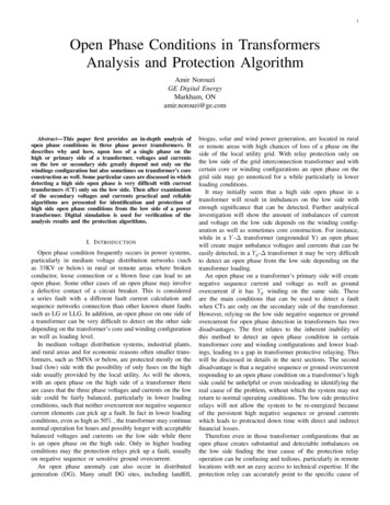
PrefaceThe production of energy using renewable natural resources such as wind,sunlight, rain, tides, geothermal heat, etc., has gained much importance in recentyears as it is an effective means of reducing greenhouse gas (GHG) emissions.The need for innovative technologies to make the grid smarter has recentlyemerged as a major trend, as the increase in electrical power demand observedworldwide makes it harder for the actual grid in many countries to keep up withdemand. Furthermore, electric vehicles (from bicycles to cars) are developed andmarketed with more and more success in many countries all over the world.To answer the increasingly diversified needs for training in the wide field ofelectrical energy, the Electric Power Technology Training Program wasdeveloped as a modular study program for technical institutes, colleges, anduniversities. The program is shown below as a flow chart, with each box in theflow chart representing a course.The Electric Power Technology Training Program. Festo Didactic 579439IX
PrefaceThe program starts with a variety of courses providing in-depth coverage of basictopics related to the field of electrical energy such as ac and dc power circuits,power transformers, rotating machines, ac power transmission lines, and powerelectronics. The program then builds on the knowledge gained by the studentthrough these basic courses to provide training in more advanced subjects suchas motor starters and drives, storage of electrical energy in batteries, homeenergy production from renewable resources (wind and sunlight), large-scaleelectricity production from hydropower, protective relaying, and smart-gridtechnologies (SVC, STATCOM, HVDC transmission systems, etc.).We invite readers to send us their tips, feedback, and suggestions forimproving the course.Please send these to services.didactic@festo.com.The authors and Festo Didactic look forward to your comments.X Festo Didactic 579439
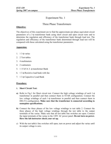
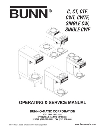
About This CoursePower transformers are one of the most commonly used electrical components.They are found in all types of applications, such as electrical power generationsystems, electrical power distribution lines, and home electronicproducts (microwave ovens, televisions, stereos, computers, grid-tied inverters).Power transformers are basically electrical devices that transfer electrical powerfrom the primary winding to the secondary winding through electromagneticinduction. While transferring power, power transformers have the ability to eitherincrease or decrease the voltage from the primary winding to the secondarywinding. Because of this, power transformers can either be used as step-uptransformers or step-down transformers. In either case, the amount of power thatis supplied to the power transformer is virtually equal to the amount of power thatthe power transformer supplies to the load. Power transformers also can provideelectrical isolation between the primary winding and the secondary winding, aspower transfer is achieved through electromagnetic induction.Autotransformers are a special type of power transformer whose primary andsecondary windings form a single winding. Because of this, autotransformers aresmaller, lighter, and cheaper than conventional power transformers for a samepower rating. Autotransformers, however, do not provide electrical isolationbetween the primary and secondary windings.This course, Single-Phase Power Transformers, teaches the basic concepts ofpower transformers. Students are introduced to the different parameters of powertransformers, such as turns, voltage, and current ratios, winding polarity, powerlosses, efficiency, voltage regulation, and operating frequency. Students learnabout different transformer connections, such as series-aiding, series-opposing,parallel, and autotransformer connections. Finally, students verify the theorypresented in each exercise by performing circuit measurements and calculations.Typical single-phase power transformer. Festo Didactic 579439XI
About This CourseSafety considerationsSafety symbols that may be used in this course and on the equipment are listedin the Safety and Common Symbols table at the beginning of this document.Safety procedures related to the tasks that you will be asked to perform areindicated in each exercise.Make sure that you are wearing appropriate protective equipment whenperforming the tasks. You should never perform a task if you have any reason tothink that a manipulation could be dangerous for you or your teammates.PrerequisiteAs a prerequisite to this course, you should have completed the followingcourses: DC Power Circuits and 1-Phase AC Power Circuits.Systems of unitsUnits are expressed using the International System of Units (SI) followed by unitsexpressed in the U.S. customary system of units (between parentheses).XII Festo Didactic 579439
To the InstructorYou will find in this Instructor Guide all the elements included in the StudentManual together with the answers to all questions, results of measurements,graphs, explanations, suggestions, and, in some cases, instructions to help youguide the students through their learning process. All the information that appliesto you is placed between markers and appears in red.Accuracy of measurementsThe numerical results of the hands-on exercises may differ from one student toanother. For this reason, the results and answers given in this course should beconsidered as a guide. Students who correctly perform the exercises shouldexpect to demonstrate the principles involved and make observations andmeasurements similar to those given as answers.Equipment installationIn order for students to be able to perform the exercises in the Student Manual,the Electric Power Technology Training Equipment must have been properlyinstalled, according to the instructions given in the user guide Electric PowerTechnology Training Equipment. Festo Didactic 579439XIII
SampleExtracted fromInstructor Guide
Exercise2Transformer Winding Polarity and InterconnectionEXERCISE OBJECTIVEWhen you have completed this exercise, you will know what the polarity of apower transformer winding is, and how to represent it in a schematic diagram.You will be able to determine the polarity of power transformer windings usingeither an oscilloscope or a voltmeter. You will also know how to connecttransformer windings in series and in parallel, as well as the effects of each typeof connection on the transformer voltage, current, and power.DISCUSSION OUTLINEThe Discussion of this exercise covers the following points: DISCUSSIONIntroduction to transformer winding polarityTransformer winding polarity in schematic diagramsDetermining the polarity of transformer windings using an oscilloscopeSeries connection of transformer windingsDetermining the polarity of transformer windings using a voltmeterParallel connection of transformer windingsIntroduction to transformer winding polarityAs seen previously, when the primary winding of a power transformer isenergized by an ac power source, an alternating magnetic flux is established inthe iron core. This alternating flux links, or couples, the turns of each winding onthe transformer and induces ac voltages in the windings. The polarity of theseinduced voltages might seem to be of minor importance for power transformerssince they are ac voltages. However, when two or more transformer windings areconnected together, their polarities have a significant effect on the resultingvoltage. If the voltage in one winding has a positive polarity when it reaches itsmaximum value while the voltage in another winding has a negative polaritywhen it reaches its maximum value, i.e., if they are 180 out of phase, thevoltages oppose each other and the resulting voltage is equal to the differencebetween the two when the windings are connected in series.The polarity of a power transformer winding refers to the polarity of the voltage atone end of the winding relative to the voltage at the opposite end of the winding,at any given instant. The polarity of a power transformer winding has no meaningin itself. It is only meaningful in relation to the polarity of the other windings.When the end of a winding is of the same polarity as the end of another windingof the transformer, it means that the polarity of the voltage at this end of eachwinding, with respect to the voltage at the other end of each winding, is the samefor both windings, and thus, that the ac voltages across these windings are inphase. Conversely, when the end of a winding is of opposite polarity to the end ofanother winding, it means that the polarity of the voltage at this end for onewinding is opposite to that of the voltage at the end of the other winding, andthus, that the ac voltages across these windings are 180 out of phase. Thepolarity of transformer windings is thus crucial when connecting windings inseries or in parallel, as will be seen later in this exercise. Festo Didactic 57943923
Exercise 2 – Transformer Winding Polarity and Interconnection DiscussionTransformer winding polarity in schematic diagramsMarkings are generally used to identify the polarity of power transformerwindings. These markings come in a variety of types, but one of the mostcommon practices in schematic diagrams is to put a dot next to the ends of thetransformer windings that have the same polarity. Figure 10 shows an example inwhich dots are used to mark the ends of the transformer windings that have thesame polarity.Power ndarywinding6Figure 10. Example of the schematic diagram of a power transformer in which dots mark thewindings that have the same polarity.In Figure 10, when the voltage at terminal 1 is positive with respect to (i.e., higherthan) the voltage at terminal 2, the voltages at terminals 3 and 6 are also positivewith respect to the voltages at terminals 4 and 5. Conversely, when the voltage atterminal 1 is negative with respect to (i.e., lower than) the voltage at terminal 2,the voltages at terminals 3 and 6 are also negative with respect to the voltages atterminals 4 and 5.Determining the polarity of transformer windings using an oscilloscopeThe polarity of each winding of a power transformer can be determined byapplying an ac voltage to one winding (generally the primary winding) and usingan oscilloscope to observe the phase of the voltage induced across each of theother windings of the transformer relative to the phase of the ac source voltage.When the phase of the voltage induced across a winding is the same as that ofthe voltage applied to the primary winding, this indicates that the windings areconnected to the oscilloscope with the same polarity, as shown in Figure 11a. Onthe other hand, when the phase of the voltage induced across a winding isopposite (phase shifted by 180 ) to that of the voltage applied to the primarywinding, this indicates that the windings are connected to the oscilloscope withopposite polarities, as shown in Figure 11b.24 Festo Didactic 579439
Exercise 2 – Transformer Winding Polarity and Interconnection DiscussionTo Ch-1 input of oscilloscope(Ch-1 probe tip)To Ch-2 input of oscilloscope(Ch-2 probe tip)Power transformerCA𝐸𝐸𝐴𝐴 𝐵𝐵Ch-1Oscilloscope displayB𝐸𝐸𝐶𝐶 𝐷𝐷DTo common point of oscilloscope(Ch-1 probe ground clip)Ch-2To common point of oscilloscope(Ch-2 probe ground clip)(a)To Ch-1 input of oscilloscope(Ch-1 probe tip)To Ch-2 input of oscilloscope(Ch-2 probe tip)Power transformerAC𝐸𝐸𝐴𝐴 𝐵𝐵Ch-1Oscilloscope displayB𝐸𝐸𝐶𝐶 𝐷𝐷DCh-2To common point of oscilloscope(Ch-2 probe ground clip)To common point of oscilloscope(Ch-1 probe ground clip)(b)Figure 11. Determining the polarity of power transformer windings using an oscilloscope.Series connection of transformer windingsTwo or more power transformer windings can be connected in series so that thetotal voltage across the windings is either the sum (series-aiding connection) ordifference (series-opposing connection) of the voltages across the individualwindings. As mentioned earlier, it is important to know the polarity of each of thewindings connected in series, as this determines whether the windings areconnected in series-aiding or in series-opposing. Festo Didactic 57943925
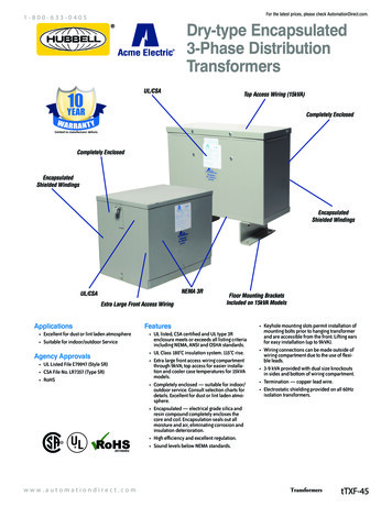
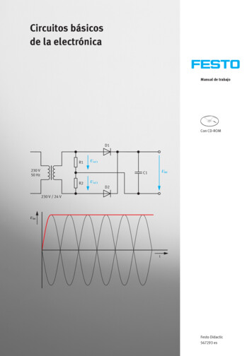
Exercise 2 – Transformer Winding Polarity and Interconnection DiscussionWhen two windings of a power transformer are connected in series so that themarked end of one winding is connected to the non-marked end of the otherwinding, the windings are connected in series-aiding, i.e., the voltage across bothwindings is equal to the sum of the voltages across each individual winding. Forexample, consider the transformer in Figure 12a. The primary winding of thetransformer has a nominal voltage of 25 V, while the secondary windings havenominal voltages of 100 V and 50 V. Since the secondary windings of thetransformer are connected in series-aiding, the total voltage across thesecondary windings is equal to 150 V (i.e., 100 V 50 V) when the primarywinding is connected to a 25 V ac power source. The transformer thus acts as astep-up transformer with a voltage ratio of 1:6.26 Festo Didactic 579439
Exercise 2 – Transformer Winding Polarity and Interconnection DiscussionPower transformer100 V25 V150 V25 V50 V(a) Series-aiding connectionPower transformer100 V25 V50 V25 V50 V(b) Series-opposing connectionFigure 12. Power transformer whose secondary windings are connected in series. Festo Didactic 57943927
Exercise 2 – Transformer Winding Polarity and Interconnection DiscussionWhen two windings of a power transformer are connected so that the markedend of one winding is connected to the marked end of the other winding, or thenon-marked end of one winding is connected to the non-marked end of the otherwinding, the windings are connected in series-opposing, i.e., the voltage acrossboth windings is equal to the difference between the voltages across eachindividual winding. For example, consider the transformer in Figure 12b. Theprimary winding of the transformer has a nominal voltage of 25 V, while thesecondary windings have nominal voltages of 100 V and 50 V (this is in fact thesame transformer as in Figure 12a. Since the secondary windings of thetransformer are connected in series-opposing, the total voltage across thesecondary windings is equal to 50 V (i.e., 100 V - 50 V) when the primary windingis connected to a 25 V ac power source. The transformer thus acts as a step-uptransformer with a voltage ratio of 1:2.Series-opposing connections are seldom used as the windings oppose eachother. Consequently, the number of wire turns required to achieve a givenac power conversion (i.e., to obtain a certain voltage) is much higher than when awinding with the exact number of wire turns is used (i.e., a winding with a numberof wire turns equal to the difference between the number of wire turns in theseries-connected windings that act in one direction and the number of wire turnsin the series-connected windings that act in the opposite direction). In theexample given in Figure 12b, the two secondary windings of the transformertotal 150 V but, when connected in series-opposing, only apply a voltage of 50 V.Thus, if a single winding with the exact number of turns is used, the transformersecondary winding requires only one third of the number of turns in two windingsconnected in series-opposing.Determining the polarity of transformer windings using a voltmeterWhen an oscilloscope is not available, the polarity of power transformer windingscan be determined by connecting the primary and secondary windings in series,then applying an ac voltage to one of the two windings (generally the primarywinding), and measuring the total voltage across the windings. When the totalvoltage is equal to the sum of the voltages across the individual windings, theends of the windings that are connected together have opposite polarities. This isillustrated in Figure 13a. In this figure, the primary and secondary windings of apower transformer, which have nominal voltages of 200 V and 100 V,respectively, are series connected. A 200 V ac power source is connected to theprimary winding. An ac voltmeter reads 300 V across the series-connectedwindings, indicating that the transformer terminals connected together are ofopposite polarity, as the windings are connected in series-aiding (i.e., the windingvoltages add up one another). Conversely, when the total voltage is equal to thedifference betw
Autotransformers are a special type of power transformer whose primary and secondary windings form a single winding Because of this, autotransformers are . smaller, lighter, and cheaper than conventional transformers for a same power power rating. Autot