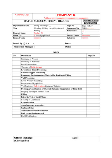
Transcription
For questions contact:Controlled Energy Corp.340 Mad River ParkWaitsfield VT 05673TOLL FREE866-330-2729www.ControlledEnergy.com/tech
Important Safety InstructionsWhen using this electrical equipment, basic safety precautions should always be followed, includingthe following:1.READ AND FOLLOW ALL INSTRUCTIONS.2.This appliance must be grounded.3.Disconnect this product from the electrical supply before cleaning, servicing or removing thecover.4.To reduce the risk of injury, close supervision is necessary when the product is used nearchildren or elderly persons.5.Warning: Do not install the heater in a location where it may be subject to freezing.6.Warning: Do not install a check valve or any other type of back flow preventer within ten feet ofthe cold water inlet.7.The electrical installation must conform to current National Electrical Codes.8.Warning: Do not switch the heater on if you suspect that it may be frozen. Wait until you are surethat it has completely thawed out.9.The PowerStar is designed to heat potable cold water for domestic purposes. The maximuminlet water temperature it can handle is 86 degrees F. Contact Controlled Energy beforespecifying or installing the appliance in any other application.10. Additional Canadian safety instructions:a) A green terminal (or a wire connector marked “G,” “GR,” “GROUND” or “GROUNDING”) isprovided within the control. To reduce the risk of electrical shock, connect this terminal orconnector to the grounding terminal of the electrical service of supply panel with acontinuous copper wire in accordance with the Canadian Electrical Code, Part I.b) This product shall be protected by a Class A ground fault circuit interrupter.ContentsUsing the PowerStar. 3Installing the PowerStar. 3Spare Parts. 7Starting up the PowerStar . 7How the PowerStar works . 9Specifications. 10If you have a problem . 10Warranty . 11SAVE THESE INSTRUCTIONSKeep this guide in a safe place once your unit has been installed.You may need to refer to it for general instructions or future maintenance.2
Using the PowerStarWARNINGDo not use the unit if you think it may be frozen, as this could result in serious damage to the unit.Wait until you are sure that it has completely thawed out before you switch it on. Check that the power is switched on at the circuit breaker panel. Turn on the hot water faucet FULLY. The hot water temperature can be changed by adjusting thetemperature dial on the bottom surface of the unit. (The dial adjusts the temperature typicallybetween 95oF and 131oF. The factory sets the temperature dial at the lowest position.) There are internal safety thermal cut-outs which will operate if the unit overheats. If a thermalcut-out trips, then it must be reset by a qualified electrician. If the unit has been used recently, run the water through for a few seconds to let the temperaturesettle down. You may initially get a short burst of very hot water from the unit. If a second outlet connected to the unit is also turned on, the hot water will be shared between thetwo.Installing the PowerStarWARNINGIMPORTANTDo not install the unit in a room where thereis a chance of freezing.Read entire instructions.Check the pressure of the main water supply. To operate correctly, the unit needs the followingrunning pressures : Minimum: 15 psi (1 Bar)Maximum: 150 psi (10 Bar)Securing the unit to the wallDiagram 1AE115 UnitAE125 Unit3
WARNINGThe unit must only be installed in the orientation shown in Diagram 1, i.e., mounted in a verticalposition with the water fittings located at the bottom of the unit. Under no circumstances shouldthe unit be mounted differently. If being used in a public place, position the unit out of easy reach to discourage vandalism. Mount the unit onto a flat section of wall, well away from any potential splashes of water or spray. Position the unit upright with all plumbing and electrical connections at the bottom of the unit.Mounting on the wall Undo the retaining screws on the front cover and take the cover off the unit. Hold the back plate inposition against the wall and mark the four mounting holes. Drill the holes and secure the unit using the four wood screws supplied or an appropriate alternativemethod.Plumbing the unitWARNINGDo not install a non-return check valve within 10 feet of the inlet. Do not apply heat or solder toconnections or pipes if they are already directly connected to the unit.Fitting the pipes The unit should be connected directly to the main cold water supply and not to pre-heated water.(The inlet water temperature must not be greater than 86oF.) The unit should be installed withshut-off valves on both the inlet and outlet connections. It is recommended that you use 3/4 inch or 1/2 inch copper or high-pressure flex connections. Use Teflon tape for sealing pipe threads. Do NOT use pipe dope. Remember to keep the hot water pipe runs as short as possible. After the unit has been plumbed, and before you wire it, flush it with water to remove any debris orloose particles. Failure to do so may make the unit inoperable.Connecting the unit to the pipes The inlet and outlet connections are clearly marked on the unit. They each have a 3/4 inch NPTconnector. Install a ball valve in the cold water line. This valve can be used to turn off the water supply to theunit if it needs servicing, or to reduce the water flow if it is too high.4
Wiring to the unitWARNINGThe unit must be installed by a qualified electrician, in accordance with the current version of theNational Electrical Code. The unit must be grounded.IMPORTANTWhen the PowerStar is not within sight of the electrical circuit breakers, a circuit breaker lockout oradditional local means of disconnection for all non-grounded conductors must be provided that iswithin sight of the appliance. (Ref NEC 422.31.) The AE115 requires two independent 240VAC circuits protected by two separate andindependent double pole breakers rated at40 A each. The AE125 requires three independent 240VAC circuits protected by three separate andindependent double pole breakers rated at40 A eachAt the circuit breaker panel there will be twoindependent double pole breakers as shownbelow.At the circuit breaker panel there will be threeindependent double pole breakers as shownbelow. The minimum recommended wire size is 8 AWG. (The terminal block will accept cables up to 6AWG size.) The cable entry is via the 1 1/4 inch cable entry hole on the bottom right hand edge of thebackplate. Strip back the insulation on the power wires about 1/2 inch. Connect the live wires to the terminalsmarked “L1” and “L2.” There are two pairs of live wires in the AE115 and three pairs of live wires inthe AE125. Any insulation on the ground wire should be stripped back about 3/4 inch. The ground lead must beconnected to the pillar terminal marked “GR.” (See Diagrams 2 and 3 on Page 6.)5
Diagram 2 (AE115 unit)GRSupply 1L1Supply 2L2L1L2Diagram 3 (AE125 unit)GRSupply 1L1Supply 2L2L1Supply 3L2L1L2 Make sure the terminal block screws are tightened securely. Loose connections can cause wires toheat up. Make sure that the ground wire is wrapped around its terminal stud and into the saddle washer.The nut should be tightened securely. Attach the front cover and tighten the retaining screws.6
Spare PartsPart NumberDescription(Refer to Diagram 1, Page 3)93 7937704 way term. block (for AE115)93 7937716 way term. block (for AE 125)93 793772Front cover93 793773Thermal cut-out93 793774Flow transducer93 793775PCB enclosure (lid)93 793776PCB enclosure (base)93 793777Control PCB (for AE115)93 793778Control PCB (for AE125)93 793779Adjustment knob93 7937843For further information ask yourlocal dealer.FOR SERVICE AND INSTALLATIONQUESTIONS CALL TOLL FREE:866-330-2729 (Toll Free)Fax: 802-496-6924www.ControlledEnergy.com/tech/4" Inlet filterStarting up the PowerStarChecking for leaks Let the water run through the unit for a few seconds. Check that no pipe joints leak.Adjusting the temperature dial The temperature adjustment is made using the dial on the bottom edge of the unit. The adjustmentis between approximately 95oF and 135oF. Turning the dial clockwise increases the temperaturesetting as indicated by the marking on the unit.Adjusting the flow Open fully both inlet and outlet shut-off valves at the heater, then : Turn on fully the highest flowing hot water faucet (e.g., bathtub) closest to the outlet connection. Adjust the outlet shut-off valve until the water flow rate from the hot faucet corresponds to the valuegiven in Graph 1 on Page 8.7
Graph 1Outlet Temperature vs Maximum Flow Rate Setting(based on incoming water temperature of 55oF)Outlet Temperature (oF)For example: For the AE115 unit, using a ball valve, ensure the flow rate does not exceed 2.3 USgallons / minute. For the AE125 unit, using a ball valve, ensure the flow rate does not exceed 3.5 USgallons / minute.Note: These figures are based on an inlet water temperature of 55oF and a supply voltage of 240volts. If the inlet water temperature is lower than 55oF, or if the supply voltage is less than 240 volts,then the outlet temperature will be lower than what is shown in Graph 1. If a higher outlet watertemperature is desired, then reduce the flow rate and/or supply the unit with 240 volts.IMPORTANTBefore leaving the site, the installer should demonstrate the unit to the user and give them this guide.8
How the PowerStar works The PowerStar heats water instantaneously as it flows through the heater modules. The electronic control monitors the flow rate and the incoming water temperature and then switcheson the required number of heater modules to reach the temperature set by the adjustment dial. As the flow rate or the incoming water temperature changes, the electronics adjust the number ofheater modules used so that the outlet temperature is maintained. The outlet water temperature can change slightly as the flow rate changes due to the steps inpower as different heater modules are switched on and off. The outlet water temperature can also vary if the maximum flow rate is exceeded (see Graph 1) or ifthe supply voltage changes. Each heater module is protected by an electro-mechanical thermal cut-out. If the temperature ofany of the heater modules gets too high, then the cut-out will trip and cut the power to that heatermodule. If the cut-out operates, it must be reset by a qualified service person. This cut-out will onlytrip in exceptional circumstances. The AE115 unit is supplied from two independent voltage supplies and the AE125 unit from threeindependent voltage supplies. The unit may continue to work if one of these supplies is switched offor fails, but the temperature control will be poor. Depending on the region of the country, the temperature of the water supply can vary between 40oFin winter to 70oF in summer, with an average of 55oF.ThermistorDiagram 4: Internal wiring schematic for single phase AE125 unit.(AE115 has two heater modules and two supplies.)9
SpecificationsVoltage supplyAmperageMaximum outputTemperature control rangePressure rangeMinimum flow rateMaximum flow rateDimensions (excl. water couplers)Weight (without water)AE115 Unit2 x 240V AC2 x 40 A17.25 kW95oF to 131oF15 psi to 150 psi0.6 US gal / minSee Graph 1, Page 8151/2” H x 151/4” W x 41/2” D20 lbsAE125 Unit3 x 240V AC3 x 40 A26.85kW95oF to 131oF15 psi to 150 psi0.8 US gal / minSee Graph 1, Page 8151/2” H x 151/4” W x 41/2” D22 lbsNote: The unit will work at lower supply voltages but the following changes will apply:Maximum output15kW at 220V22.5kW at 220V13kW at 208V20kW at 208VTemperature control range87oF to 116oF at 220V87oF to 116oF at 220V82oF to 108oF at 208V82oF to 108oF at 208VMaximum flow rate84% of maximum at 220V84% of maximum at 220V(refer to Graph 1, Page 8)75% of maximum at 208V75% of maximum at 208VWARNINGAlways switch off the electricity supply to the unit before you remove the cover.If you have a problem.Service should only be performed by qualified personnelSymptomCauseElectricity not on or one of thesupplies has failed.Check electricity supply.The water supply is connectedto the outlet of the unit.Reconnect the water supply tothe inlet of the unit (markedblue).One or more of the heatermodule cut-outs has tripped.Turn off the power, open the unitand reset by pushing thebutton(s) on the top of the heatermodule(s). Establish and fix thecause of the overheating.Plumbing crossover.Test by turning cold water supplyoff to heater, then open hot waterfaucet(s). No pressurized waterflow should be evident. If it isevident, then that plumbingcrossover needs to be correctedfor the heater to operate.The flow transducer is notworking.Turn off the power, open the unitand observe if the flowtransducer "spins" when thewater is turned on. If not, contactCEC toll free at 866-330-2729.Cold water only –neon light off.10What to do
SymptomWater too cold –neon light onWater flow too lowWater te
The PowerStar is designed to heat potable cold water for domestic purposes.The maximum inlet water temperature it can handle is 86 degrees F. Contact Controlled Energy before specifying or installing the appliance in any other application. 10. Additional Canadian safety instructions: a) A green terminal (or a wire connector marked “G,” “GR,” “GROUND” or “GROUNDING”) is provided .