Transcription
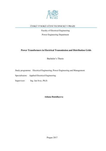
ČESKÉ VYSOKÉ UČENÍ TECHNICKÉ V PRAZEFaculty of Electrical EngineeringPower Engineering DepartmentPower Transformers in Electrical Transmission and Distribution GridsBachelor’s ThesisStudy programme: Electrical Engineering, Power Engineering and ManagementSpecialisaion:Supervisor:Applied Electrical EngineeringIng. Jan Svec, Ph.D.Aidana IbatullayevaPrague 2017
DeclarationI hereby declare that this thesis is the result of my own work and all the sources I used arein the list of references, in accordance with the Methodological Instructions of EthicalPrinciple in the Preparation of University Thesis.In Prague, 26.05.2017Signature .
AcknowledgementI would like to thank my thesis advisor Ing. Jan Svec who has coordinated me since thebeginning and doc. Dr. Ing. Jan Kyncl for guiding and supporting me during the thesis.I wish to express my sincere gratitude to my parents for their endless love and encouragementthrough the duration of my studies.
AbstractThis Bachelor thesis is about the basics of Power Transformers, such as construction,electrical parameters, special types and their usage, brief explanation of technical aspects andpractical problems in utilization. In the end of work basic calculations during their operationin ES are presented.Key wordsTransformer, construction, transformer cooling, parallel operation, transformer losses.AbstraktTato bakalářská práce se zabývá základy výkonových transformátorů, jako konstrukce,elektrické parametry, speciální typy a jejich využití, stručné vysvětlení technických aspektů apraktické problémy využití. Na závěr práce jsou prezentovány základní výpočty během jejichprovozu .Klíčová slovaTransformátor , konstrukce, chlazení transformátoru, paralelní provoz, ztráty transformátoru.
Table of contentsPREFACEABSTRACT1. Introduction . . .12. General description of transformers . 22.1. Principle of operation . . . 32.2. Principle of working . . . .42.3. Operation of transformer . . . .52.3.1. Equivalent circuit of transformer . . .52.3.2. Electromotive force in windings . .62.4. Short-circuit state and short-circuit test . . .82.5. No-load state and no-load test . .92.6. Under load state .103. Types of transformers . . . .133.1. Transformers in Power System .143.2. Special types of transformers .153.2.1. Instrument transformers .153.2.2. Autotransformers .173.2.3. Transformer taps 194. Transformer connections .214.1. Three-phase transformer connections .215. Technical aspects of transformers 265.1. Transformer Cooling .265.1.1. Transformer cooling methods 275.1.1.1. Dry type transformers . .275.1.1.2. Oil-immersed transformers . 285.2. Losses in Transformer 315.2.1. No-Load losses .315.2.2. Load losses .315.2.3. Extra losses .325.2.4. Auxiliary losses .34
6. Materials for manufacturing of transformers . .356.1. Materials for magnetic core . . 356.2. Materials for windings 367. Practical problems in utilization of transformers . .387.1. Parallel operation of transformers .387.2. Calculations . .407.2.1. Short-circuit level .407.2.2. Voltage drop .418. Conclusion .43REFERENCES .44
1.IntroductionTransformers are important component in our current life and they make large power systemspossible. To effectively transfer hundreds of megawatts of power over long distances, very highline voltages are required - in the range of 161 to 1000 kV. However, the highest practical designvoltage for large generators is about 25 kV. How can electrical power be generated at 25 kV andtransmitted at a much higher voltage? Transformers can provide the solution to this problem.They can step voltages up or down with a very small loss of power. Connecting a step-uptransformer between the generator and a transmission line allows the creation of a practicaldesign voltage for the generator and at the same time an effective transmission line voltage. Withstep-down transformers connected between the transmission line and the various electrical loadsconnected to it, it is allowed to use the transmitted power at a safe voltage. Without them, itwould be impossible to develop large power systems that exist today.In ideal case, a transformer should not make any changes to the power factor and should havezero internal power loss. If 𝑃1 is the input power for a three-phase transformer and 𝑃2 its outputpower, the following relationship must be satisfied for an ideal three-phase transformer: 3𝑉𝐿1 𝐼𝐿1 𝑐𝑜𝑠𝜃 𝑃1 𝑃2 3𝑉𝐿2 𝐼𝐿2 𝑐𝑜𝑠𝜃 (1)where,𝑉𝐿1 - line-to-line voltage at the input terminals of the transformer, [V]𝐼𝐿1 - input line current, [A]𝑉𝐿2 - line voltage at the output terminals, [V]𝐼𝐿2 - output line current, [A]𝜃 - angle between phase current and phase voltage (The angle between phase current andphase voltage is assumed to beunchanged between input and output)𝑐𝑜𝑠𝜃 - power factor.Then, solving Equation 1 for the current ratio,𝐼𝐿1𝐼𝐿2 𝑉𝐿2𝑉𝐿1(2)It is clear that, when the transformer steps up the voltage, it proportionately reduces thecurrent. Since the losses in transmission lines are proportional to square of the line current (𝐼 2 𝑅),it is obvious that the high transmission line voltages, which can be obtained with the help oftransformers, increase the efficiency of the power system by reducing the line currents.1
2.General description of transformerA transformer is a four-terminal device that transforms an AC input voltage into a higher orlower AC output voltage. It transforms power from a particular circuit to another with nofrequency changes regardless of the voltage levels. The transformer consists of three maincomponents: primary winding, which acts as an input, the second coil secondary winding, whichacts as the output, and the iron core, which serves to strengthen the magnetic field generated.Transformer has no internal moving parts, and it transfers energy from one circuit to anotherby electromagnetic induction. External cooling may include heat exchangers, radiators, fans, andoil pumps. Transformers typically used because a change in voltage is needed. Powertransformers are defined as transformers rated 500 kVA and larger (In figure 1 is shown typicalpower transformer).Figure 1. Power transformerTransformers transfer electrical energy between circuits completely insulated from each otherand this allows using very high (stepped-up) voltages for transmission lines, resulting in a lower(stepped-down) current. Higher voltage and lower current reduce the required size and cost oftransmission lines and reduce transmission losses.2
They do not require, as much attention as most other devices; nevertheless, the care andmaintenance, which they really require, is absolutely necessary. Because of their reliability,maintenance is sometimes ignored, which reduces service life and sometimes outright failure.2.1.Principle of operationThe function of the transformer is based on the principle that electrical energy is transferredefficiently by magnetic induction from one circuit to another. When one winding of thetransformer is energized from an AC source, an alternating magnetic field is installed in thetransformer core. Alternating magnetic lines of force, which circulate through the core, are called“flux”. With a second winding around the same core, voltage is induced by the alternating fluxlines. A circuit, connected to the terminals of the second winding, results in current flow.Figure 2. Transformer ConstructionEach phase of a transformer consists of two separate coil windings, wound on a common core.The low-voltage winding is located closer to the core; the high-voltage winding is then placedaround the low voltage winding and core. We can see from figure 2 internal construction of onephase. The core is usually made from very thin steel laminations, each of which is covered withinsulation. Isolation between individual laminations reduces losses. The steel core provides a lowresistance path for magnetic flux. High-voltage and low-voltage windings are isolated from thecore and from each other, and leads are brought out through insulating bushings. A three-phase3
transformer typically has a core with three legs and has around each leg both high-voltage andlow-voltage windings. For insulation and internal structural support are used special paper andwood.2.2.Principle of workingBasically, a transformer is very simple static (or stationary) electro-magnetic passive electricaldevice that works on the principle of Faraday’s law of induction by converting electrical energyfrom one value to another. Actually, mutual induction between two or more winding isresponsible for transformation action in an electrical transformer. Faraday's Laws ofElectromagnetic Induction (second law) states that the magnitude of emf (E) induced in thecoil is equal to the rate of change of flux that linkages with the coil. The flux linkage of the coilis the product of number of turns in the coil and flux associated with the coil. 𝑬 𝑼 𝒅𝝍𝒅𝒕 𝑵𝒅𝝓𝒅𝒕(3)Figure 3. Topology of induction coils and real transformersAs we said before, transformer has three main parts, which are:o Primary winding of transformer - produces magnetic flux when it is connected toelectrical source.oSecondary winding of transformer – output winding. The flux, produced by primarywinding, passes through the core and will link with the secondary winding.o Magnetic Core of transformer - the flux produced by the primary winding, that will passthrough this low reluctance path linked with secondary winding and create a closedmagnetic circuit.4
2.3.Operation of transformer2.3.1. Equivalent circuit of a transformerThe equivalent circuit is used to simplify circuit analysis and helpful in predetermining thebehavior of the transformer under the various conditions of operation.In figure below are full description of a �𝐼0𝐼1𝐼2′Figure 4. Equivalent circuit of transformer.where:𝑅1 and 𝑅2′ - the primary and secondary winding resistances (denoted respectively).The resistances cause voltage drops as 𝐼1 𝑅1 and 𝐼2 𝑅2 and also copper losses 𝐼12 𝑅1 and 𝐼22 𝑅2 .′𝑋1𝜎 , 𝑋2𝜎 leakage flux in both primary and secondary side give rise to leakage reactance at bothside (denoted respectively).𝑅𝐹𝑒 – the iron-core resistance having the value corresponding to power loss in the magnetic circuit:2Δ𝑃 Δ𝑃𝐹𝑒 𝑅𝐹𝑒 𝐼1𝐹𝑒(4)𝑋1ℎ – magnetizing reactance of primary circuit corresponding to mutual flux and representingprimary Electromotive force (emf- described later).5
igure 5. Concise equivalent circuit of transformerFigure 5 is a reduced version from circuit above (figure 4), it represents the impedance Z which iscombined from reactance and resistance of transformer. From this reduced circuit we can easilydescribe the operation of transformer by following equations:𝑍0 𝑅𝐹𝑒 .𝑗𝑋1ℎ𝑅𝐹𝑒 𝑗𝑋1ℎ(5)𝑍1 𝑅1 𝑗𝑋1𝜎(6)′𝑍′2 𝑅′2 𝑗𝑋2𝜎(7)𝑈1 𝑍1 𝐼1 𝑍0 𝐼0(8)𝑈′2 𝑍′2 𝐼′2 𝑍0 𝐼0(9)𝑍- All values are denoted as impedances for primary, iron-core, secondary winding (respectively).𝑈1 Voltage on primary winding; 𝑈′2 Voltage on secondary winding.Note: All equations above are represented in phasor form.2.3.2.Electromotive force in windingsEMF Equation of transformer can be determined very simple. In fact, in power transformer, onealternating electrical source is applied to the primary winding and due to this, magnetizingcurrent flowing through the primary winding, which produces alternating flux in the core oftransformer. However, this flux links with both primary and secondary windings. Since this flux6
is alternating in nature, there must be a rate of change of flux. This phenomenal is related toFaraday’s law and can be described by following equations:𝑑𝜙𝑈𝑖 𝑁 𝑑𝑡(10)where 𝜙 is the instantaneous alternating flux and it can be represented as:𝜙 𝜙ℎ𝑚 𝑠𝑖𝑛𝜔𝑡(11)𝑈𝑖 𝑁𝜙ℎ𝑚 𝜔 𝑐𝑜𝑠𝜔𝑡(12)Using equation 11 we ll find 𝑈𝑖RMS value of induced emf in whole primary winding 𝑈𝑖1 is:𝑈𝑖1 4,44𝑓𝑁1 𝜙𝜇𝑚𝑎𝑥(13)Similarly, RMS induced emf in secondary winding (𝑈𝑖2 ) can be given as:𝑈𝑖2 4,44𝑓𝑁2 𝜙𝜇𝑚𝑎𝑥(14)where:𝑈𝑖1 , 𝑈𝑖2 - Voltages generated by EMF in primary and secondary windings (denoted respectively)f – frequency of applied AC source𝑁1 , 𝑁2 – Number of turn of coils in primary and secondary windings (denoted respectively)𝜙𝜇𝑚𝑎𝑥 – The maximum rate change in flux generated by magnetic circuit.Note: The convention of 𝑈𝑖 in all equations are effective values!Finally, from the above equations 13 and 14 we have general equation of electromotive force fortransformer.𝑝 𝑁1𝑁2 𝑈𝑖1𝑈𝑖2(15)This constant (p) is called transformation ratio of transformer. If N2 N1, i.e. p 1, then the transformer is step up transformer. If N2 N1, i.e. p 1, then the transformer is step down transformer.7
2.4.Short-circuit state and short-circuit testShort circuit test on transformer is used to determine copper loss in transformer at full load andparameters of approximate equivalent circuit of transformer. At short circuit, the secondaryterminals of transformer are short-circuited. 𝑈2 0 and 𝐼2 and 𝐼1 can be very high (depending onvoltage). They are much higher than Io, therefore, after assuming Io 0 the equivalent circuit canbe ���𝑅1′𝑈𝑋2′𝑈𝑅2𝑈1E𝑈2′ igure 6. Equivalent short-circuit of transformerWe determine the following parameters:short-circuit resistance and reactance𝑅𝑘 𝑅1 𝑅2′ and 𝑋𝑘 𝑋1 𝑋2′(16)then, short-circuit impedance, sometimes called as equivalent impedance of transformer𝑍𝑘 𝑅𝑘 𝑗𝑋𝑘𝑍𝑘 𝑈1𝐼(17)(18)In laboratory or during field tests the short-circuit tests are very often performed. For the voltagechanges from zero up to the value providing the current flow not too much higher than 𝐼𝑁(nominated current), 𝑃1 ,𝐼1 ,𝑐𝑜𝑠𝜑 are measured and their characteristics drawn as:8
Figure 7. Characteristics of 𝑃1 ,𝐼1 ,𝑐𝑜𝑠𝜑For 𝐼1 𝐼𝑁 we determine and specify:U 𝑈𝑘 – short-circuit voltage (having two components: 𝑈𝑅𝑘 and𝑈𝑋𝑘 );𝑃1 𝑃𝑘 – short-circuit power;𝑐𝑜𝑠𝜑 cos 𝜑𝑘 – short-circuit power factor.Short-circuit voltage is the value of supplying voltage in short-circuited transformer that providesa flow of rated currents (𝐼2 and 𝐼1 ). Its value is always shown in ratings of transformers ornameplates (usually in p.u. or in %).Typical percent value of short-circuit voltage is: several % for small and medium power transformers, 10 to 20% for large power transformers (hundreds of MVA).Short-circuit power, i.e. the power absorbed by short-circuited transformer is totally “lost” in thetransformer (the output power 𝑃2 0). The iron losses in such transformer are much smaller whencompared to copper loss and can be neglected.2.5.No-load operation and no-load testAt no-load state, the secondary circuit of the transformer is opened:𝐼2 0 and 𝐼1 𝐼𝑁 (𝐼𝑁 - nominated current)No-load test of the transformer is easy to be made in laboratory or even in a substation:TRIAW𝑉1𝑉2Figure 8. Measuring circuit diagram.9
*RI – induction regulator (voltage source of variable output),A – ammeter,V – voltmeter,W – wattmeter.During the test, the supplying voltage is varied from 0 up to 𝑈𝑁 (sometimes more). The followingquantities are measured: 𝑈1 ; 𝑈2 ; 𝐼0 ; 𝑃1𝑜 𝑋2′𝑋1𝐼𝑓𝐼0 ���𝐹𝑒𝑈2′Figure 9a. Equivalent circuit of two-winding transformerwhere ,𝐼0 – no-load current𝐼𝑓 – magnetizing current (reactive component of no-load current)𝐼𝑜𝑤 – active component of no-load currentAppropriate characteristics are drawn in the function of primary voltage:Figure 9b. Basic no-load characteristicsFrom the no-load test results, we can determine some parameters of the transformer being testedor its equivalent circuit:10
𝑐𝑜𝑠𝜑 𝑅𝐹𝑒𝑃1𝑜,𝑈1 𝐼0𝐼𝑜𝑤 𝐼0 𝑐𝑜𝑠𝜑0 , 𝑃0𝑈12𝑈12 2 ,𝐼𝑜𝑤 𝑃0 𝑃𝐹𝑒𝑋𝑓 (19)𝐼𝑓 𝐼0 𝑠𝑖𝑛𝜑0𝑈1𝐼𝑓(20)Rated no-load current (i.e. the value of no-load current at rated voltage) expressed in p.u. or inpercent𝐼𝑜𝑁% 𝐼𝑜𝑁 100%𝐼𝑁(21)is rather of small value: from a few % in large power transformers to 20-30% in small transformers.2.6.Under load stateFor simplified consideration of the transformer operation under load we can apply its simplifiedequivalent 𝑘𝑈2′Figure 10. Simplified equivalent circuitSimplification of equivalent circuit (EC) leads to some error – much lower when 𝐼0 is smaller incomparison to 𝐼1 or 𝐼2 currents. Hence, we can use such equivalent circuit (EC) for discussingpower transformers fully loaded.Using such this model, we can consider the problem of output voltage variation for different valueand character of the load current. Let us consider the following problem:transformer is supplied with constant primary voltage 𝑈1 and the loading current 𝐼2 varies. Thecharacter of load current is given by its phase angle 𝜑2 varying at closed interval [-90 , 90 ].For I2’ I 0 the output voltage U’2o U1. For I 0 and some 𝜑2*U2o is no-load output voltage for U1 U1N11
Figure 11. Voltage drops triangleWe observe the voltage drop 𝑈 (difference in voltage values)′ 𝑈 𝑈1 𝑈2′ 𝑈2𝑜 𝑈2′ 𝐼𝑅𝑘 𝑐𝑜𝑠𝜑2 𝐼𝑋𝑘 𝑠𝑖𝑛𝜑2,(22)Assuming 𝑈1 𝑈1𝑁 and expressing 𝑈 in in per units′𝑈2𝑜𝑁 𝑈2′𝐼 𝑈𝑟 (𝑅𝑘𝑟 𝑐𝑜𝑠𝜑2 𝑋𝑘𝑟 𝑠𝑖𝑛𝜑2 ),′𝑈2𝑜𝑁𝐼𝑁(23)and for 𝐼 𝐼𝑁 : (where 𝑈𝑅𝑘𝑟 𝑅𝑘𝑟 and 𝑈𝑋𝑘𝑟 𝑋𝑘𝑟 ) 𝑈𝑟𝑁 𝑅𝑘𝑟 𝑐𝑜𝑠𝜑2 𝑋𝑘𝑟 𝑠𝑖𝑛𝜑2 𝑈𝑅𝑘𝑟 𝑐𝑜𝑠𝜑2 𝑈𝑋𝑘𝑟 𝑠𝑖𝑛𝜑2 ,(24)The function ΔU 𝑓(𝑐𝑜𝑠𝜑2 ) for I 𝐼𝑁 is shown in following figureFigure 12. Dependence of ΔU on 𝑐𝑜𝑠𝜑2It is seen that max(ΔU) 𝑈𝑘 occurs at 𝑐𝑜𝑠𝜑2 𝑐𝑜𝑠𝜑𝑘 i.e. for very special value being a knownparameter of the transformer (short-circuit power factor).*lead leading character of the current, i.e. the current of capacitive character, or current phasorleads the voltage phasor;*lag lagging character of the load, inductive load, current phasor lags the voltage phasor.12
3.Types of TransformersIn this part, we are not discussing in detail about each type of transformer, so I described ingeneral types of transformer according to their usages, shapes, use etc.o Step up Transformer & Step down Transformer - They are used for stepping up and downthe voltage level of power in transmission and distribution power system network.o Three Phase Transformer & Single Phase Transformer - Former, as a rule, is used in threephase power system, as it is more cost effective than later. However, when size matters, it ispreferable to use a bank of three single-phase transformer, as it is easier to transport than onesingle three-phase transformer unit.o Electrical Power Transformer, Distribution Transformer – Power Transformer is transferringenergy between high voltage and very high voltage systems, i.e. between generators andtransmission systems and between transmission systems and distribution systems. Also, theyare used in transmission network for stepping up or down the voltage level. It operatesmainly during high or peak loads and has maximum efficiency at or near full load.Distribution transformer steps down the voltage for distribution purpose to domestic orcommercial users. It has good voltage regulation and operates 24 hours a day with maximumefficiency at 50% of full load.o Indoor Transformer & Outdoor Transformer - Transformers that are designed for installing atindoor are indoor transformers and transformers designed for installing at outdoor are outdoortransformers.o Oil Cooled & Dry Type Transformer - In oil cooled transformer the cooling medium istransformer oil whereas in dry type transformers air is used as the cooling medium instead ofoil.o Phase-Shifting Transformer- A phase-shifting transformer is a device for controlling thepower flow through specific lines in a complex power transmission network.Purposes of Phase-Shifting transformers:a) To control the power flow between two large independent power systems;b) To change the effective phase displacement between the input voltage and the outputvoltage of a transmission line, thus controlling the amount of active power that can flow inthe line.13
3.1.Transformers in Power Systems (Transmission and Distribution systems)Transmission refers to the bulk transfer of power by high-voltage links between centralgeneration and load centres. Distribution, on the other hand, describes the conveyance of thispower to consumers by means of lower voltage networks.Modern transformers used in transmission and distribution systems have very highefficiencies up to 90%-99%. This means that they can transmit up to 90%-99% of the electricalenergy input to them when stepping up or stepping down the voltage.Transmission: Generators usually produce voltages in the range 11–25kV, which is increasedby transformers to the main transmission voltage. At substations, the connections between thevarious components of the system, such as lines and transformers, are made and the switching ofthese components is carried out. Large amounts of power are transmitted from the generatingstations to the load-centre substations, for example at 400kV and 275kV in Britain, and at 765,500 and 345kV in the USA.Distribution Systems: Distribution networks differ from transmission networks in several ways,quite apart from their voltage levels. The number of branches and sources is much higher indistribution networks and the general structure or topology is different. A typical system consistsof a step-down (e.g. 132/11kV) on-load tap-changing transformer at a bulk supply point feedinga number of circuits which can vary in length from a few hundred metres to several kilometres.A series of step-down three-phase transformers, for example, 11kV/433V in Britain or4.16kV/220V in the USA, are spaced along the route and from these are supplied the consumerthree-phase, four-wire networks which give 240V, or, in the USA, 110V, single-phase suppliesto houses and similar loads.Figure 13. Electric Power system14
A large number of transformers of different classes and sizes are needed in the transmissionand distribution network, with a wide range of operating voltages. The last transformation stepinto the consumer mains voltage (in Europe 400/230V) is done by the distribution transformer.Distribution transformers operated and owned by electricity distribution companies areresponsible for supplying about 70% of low voltage electricity to final users. Voltage levels areclassified as: Extra high voltage: transmission grid( 150kV) typically 220–400kV(ultra high 400kV) High voltage 70 kV up to 150 kV Medium voltage 1 kV up to 70 kV (typically up to 36 kV) Low voltage 1kV (e.g. 110V, 240V, 690 V).3.2.Special types of transformers3.2.1. Instrument transformersInstrument transformer is an electrical device used to transform current as well as voltagelevel. Sometimes, they are also called as isolation transformers. Instrument transformers arecommonly used to safely isolate the secondary winding when the primary has high currentsupply and high voltage so that the measuring instrument relays or energy meters, which areconnected to the secondary side of the transformer will not get damaged. The instrumenttransformer is divided into two types: Current Transformer (CT) and Potential Transformer (PT)o Current Transformer (CT)The CT is used for measuring and for the protection. The primary of a current transformertypically has only one turn, it never has more than a very few turns, while the secondary canhave a great many turns, depending upon how much the current must be stepped down. In a lotof cases, the primary of a current transformer is a single wire or bus bar, and the secondary iswound on a laminated magnetic core, placed around the conductor in which the current needs tobe measured (see figure 14).15
Figure 14. Current transformerThe CT is typically described by its current ratio from primary to secondary, for example, ifits ratio is 2000:5, it means a CT has an output current of 5 amperes when 2000 amperes areflowing through its primary winding. They are used with ammeters, wattmeters, power factormeters, watt-hour meters, compensators, protective and regulating relays, and trip coils of circuitbreakers. Actually, one current transformer can be used to operate several instruments, providedthe combined loads of the instruments do not exceed that for which the CT is rated. Secondarywindings are usually rated at 5 amperes.o Potential Transformers (PT)The potential transformer is also called as the voltage transformer. The main function of thePotential transformer (PT) is to step down the voltage level to a safe limit or value. They areused with voltmeters, wattmeters, watt-hour meters, power-factor meters, frequency meters,synchronizing apparatus, protective and regulating relays, and under voltage and overvoltage tripcoils of circuit breakers. One potential transformer may be used for a number of instruments ifthe total current required by the instruments connected to the secondary winding does not exceedthe transformer rating.16
Figure 15. Potential or voltage transformer.3.2.2. AutotransformersAn Autotransformer is a transformer with only one winding wound on a laminated core. Theyare less costly and smaller for small voltage changes than standard transformers.Autotransformers transfer much of the power directly through a wire connection. Moreover, lesscurrent flows through the shunt winding, whereas most of the current passes through the lowervoltage series winding at the top.This type of transformers have two main applications on distribution systems: Voltage regulators: The regulator is an autotransformer with adjustable taps, which, as arule, is able to regulate the voltage by 10%. Step banks: Generally, autotransformers are often used instead of traditional transformerson step banks and even substation transformers, where the relative voltage change ismoderate.17
Autotransformer with an equivalent circuit is shown in figures 16a, b below.𝐼2𝑛2𝐼1 𝑛2𝑉𝑛1 1- Load 𝑛1𝑉1-𝑛2𝐼𝑛1 2𝑉2-Figure 16a. Autotransformer with an equivalent circuit𝐼2 𝑛1𝐼1𝐼1 ,𝑛1 𝑛2𝑏𝑉2 𝑉1 𝑛2𝑉 𝑏𝑉1 ,𝑛1 1(25)(26)Where,b- Voltage change ratio, in per unit and it is equal to:𝑛1 𝑛2,𝑛1(27)𝑛2 𝑏 1,𝑛1(28)𝑏 Figure 16b. Equivalent model18
The required rating of the autotransformer depends on the voltage change between the primaryand secondary windings. The rating of each winding as a percentage of the load is defined as:𝑆 𝑏 1𝑏(29)To obtain a 10% voltage change (b 1.1), an autotransformer only has to be rated at 9% of theload kVA. For a 2:1 voltage change (b 2), an autotransformer has to be rated at 50% of the loadkVA. By comparison, a standard transformer must have a kVA rating equal to the load kVA.The series impedance of autotransformers is less than an equivalent standard transformer. Andthe equivalent series impedance of the autotransformer is defined as:𝑍𝑎𝑢𝑡𝑜 (Where,𝑏 1 2) 𝑍𝑏(30)Z - impedance across the entire winding (see fig 16b).3.2.3. Transformer TapsMost power transformers have taps on the primary or secondary windings to change thenumber of turns and, consequently, the output voltage. The percentage of voltage variation,above or below normal, between different tap positions varies in different transformers.Taps onoil-cooled transformers are brought to an oil-filled tap changer, which is externally located orbrought to a tap changer, located under the oil inside the tank. Taps on dry-type transformers arebrought to insulated terminal boards, which is located inside the metal housing, accessible byremoving a panel.Tap changers connected to the primary or secondary side windings of the transformer dependingon:-Current rating of the transformer;-Insulation levels present;-Type of winding within the transformer (eg. Star, delta or autotransformer);-Position of tap changer in the winding;-Cost;-Physical size.19
Tap changers are divided into two types: On-load (OLTC) Off-load/de-energized (DECT).Off-load tap-changing (manual tap changing) mechanisms require the transformer to beisolated before its tap settings can be adjusted, and is normally the case with smaller distributiontransformers. However, since the off-load tap changer causes interruption in the supply on-loadtap changers are more preferred today in power system.The on-load tap-changer (automatic changing) allows to select the ratio change when thetransformer is in service. This means that the transformer ratio may be changed while the power(current) is still flowing through it. On-load tap changers generally consist of a diverter switchand a selector switch operating as a unit to effect transfer current from one voltage tap to thenext. The resistors in the diverter switch are typically a few ohms.Figure 17. Typical on-load tap changer20
4.Transformer connections4.1. Three-phase transformer connectionsThree-phase connections can be made either by using three single-phase transformers or by usinga three-phase transformer. Advantages of the three-phase transformer are:o it costs less;o the weight is less;o it requires less floor space;o has lower losses than three single-phase transformers.The methods of connecting windings will be the same, whether using the one three-phasetransformer or three separate single-phase transformers. The two general methods of connectingthree-phase transformers are shown in figure 18.Figure 18. Three-phase transformer connections
power transformer). Figure 1. Power transformer Transformers transfer electrical energy between circuits completely insulated from each other and this allows using very high (stepped-up) voltages for transmission lines, resulting in a lower (stepped-down) current. Higher voltage and lower current reduce the required size and cost ofFile Size: 2MB


