Transcription
EE6404MEASUREMENTS&INSTRUMENTATIONA Course Material onMeasurements and InstrumentationByMr.N.KannapiranASSISTANT PROFESSORDEPARTMENT OF ELECTRONICS AND COMMUNICATION ENGINEERINGSASURIE COLLEGE OF ENGINEERINGVIJAYAMANGALAM – 638 056SCE1Department of EEE
EE6404MEASUREMENTS&INSTRUMENTATIONQUALITY CERTIFICATEThis is to certify that the e-course materialSubject Code : EE 6404Subject: Measurements and InstrumentationClass: II Year EEEbeing prepared by me and it meets the knowledge requirement of the university curriculum.Signature of the AuthorN.KannapiranASSISTANT PROFESSORThis is to certify that the course material being prepared by Mr.N.Kannapiran is of adequatequality. He has referred more than five books among them minimum one is from abroad author.Signature of HDS.SRIRAMASSISTANT PROFESSORSCE2Department of EEE
EE6404MEASUREMENTS&INSTRUMENTATIONS.NOCONTENTSPAGE NOUNIT I INTRODUCTION1.1Functional elements of an instrument1.2Static and dynamic characteristics1.3Errors in measurement1.4Statistical evaluation of measurement data1.5Standards and calibrationUNIT II ELECTRICAL AND ELECTRONICS INSTRUMENTS2.1Principle and types of analog and digital voltmeters2.2Ammeters & Multimeters2.3Single and three phase wattmeters and energy meters2.4Instrument transformers2.5Magnetic measurements2.6Determination of B-H curve and measurements ofiron lossUNIT III COMPARISON METHODS OF MEASUREMENTS3.1D.C & A.C potentiometers3.2D.C & A.C bridges3.3Transformer ratio bridges & Self-balancing bridges3.4Interference & screening3.5Electrostatic and electromagnetic interference3.6Grounding techniques3.7Multiple earth and earth loopsUNIT IV STORAGE AND DISPLAY DEVICESSCE4.1Recorders4.2Magnetic disk and tape4.3Digital plotters and printers4.4CRT display4.5digital CRO3Department of EEE
EE6404MEASUREMENTS&INSTRUMENTATION4.6Data Loggers4.7LED4.8LCD & dot matrix displayUNIT V TRANSDUCERS AND DATA ACQUISITION SYSTEMSSCE5.1Classification of transducers5.2Selection of transducers5.3Resistive transducers5.4Capacitive transducers5.5Inductive transducers5.6Digital transducers5.7Piezoelectric transducers5.8Hall effect transducers5.9Elements of data acquisition system5.10A/D converters5.11D/A converters5.12Smart sensors5.13Optical transducersAQuestion BankBUniversity Questions4Department of EEE
EE6404MEASUREMENTS&INSTRUMENTATIONOBJECTIVES:To introduce the basic functional elements of instrumentationTo introduce the fundamentals of electrical and electronic instrumentsTo educate on the comparison between various measurement techniquesTo introduce various storage and display devicesTo introduce various transducers and the data acquisition systemsUNIT I INTRODUCTION 9Functional elements of an instrument – Static and dynamic characteristics – Errors inmeasurement –Statistical evaluation of measurement data – Standards and calibration.UNIT II ELECTRICAL AND ELECTRONICS INSTRUMENTS9Principle and types of analog and digital voltmeters, ammeters, multimeters – Single and threephase wattmeters and energy meters – Magnetic measurements – Determination of B-H curveand measurements of iron loss – Instrument transformers – Instruments for measurement offrequency and phase.UNIT III COMPARISON METHODS OF MEASUREMENTS9D.C & A.C potentiometers, D.C & A.C bridges, transformer ratio bridges, self-balancingbridges. Interference & screening – Multiple earth and earth loops - Electrostatic andelectromagnetic interference – Grounding techniques.UNIT IV STORAGE AND DISPLAY DEVICES 9Magnetic disk and tape – Recorders, digital plotters and printers, CRT display, digital CRO,LED, LCD & dot matrix display – Data Loggers.UNIT V TRANSDUCERS AND DATA ACQUISITION SYSTEMS 9Classification of transducers – Selection of transducers – Resistive, capacitive & inductivetransducers – Piezoelectric, Hall effect, optical and digital transducers – Elements of dataacquisition system – A/D, D/A converters – Smart sensors.TOTAL :45 PERIODSOUTCOMES:Ability to model and analyze electrical apparatus and their application to power systemTEXT BOOKS:1. A.K. Sawhney, ‘A Course in Electrical & Electronic Measurements & Instrumentation’,Dhanpat Rai and Co, 2004.2. J. B. Gupta, ‘A Course in Electronic and Electrical Measurements’, S. K. Kataria & Sons,Delhi, 2003.3. Doebelin E.O. and Manik D.N., Measurement Systems – Applications and Design, SpecialIndian Edition, Tata McGraw Hill Education Pvt. Ltd., 2007.REFERENCES:1. H.S. Kalsi, ‘Electronic Instrumentation’, Tata McGraw Hill, II Edition 2004.2. D.V.S. Moorthy, ‘Transducers and Instrumentation’, Prentice Hall of India Pvt Ltd, 2007.3. A.J. Bouwens, ‘Digital Instrumentation’, Tata McGraw Hill, 1997.4. Martin Reissland, ‘Electrical Measurements’, New Age International (P) Ltd., Delhi, 2001.SCE5Department of EEE
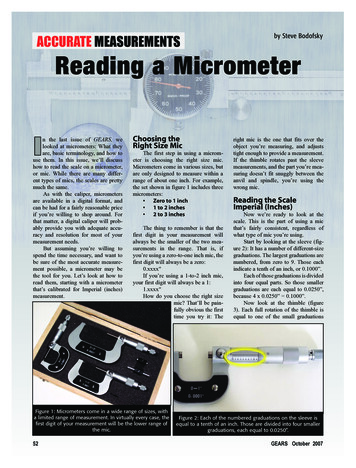
EE6404MEASUREMENTS&INSTRUMENTATIONUNIT I INTRODUCTIONMEASUREMENTS:The measurement of a given quantity is essentially an act or the result of comparisonbetween the quantity (whose magnitude is unknown) & a predefined standard. Since twoquantities are compared, the result is expressed in numerical values.BASICREQUIREMENTSOFMEASUREMENT:i)ii)The standard used for comparison purposes must be accurately defined &should be commonly acceptedThe apparatus used & the method adopted must be provable.MEASURINGINSTRUMENT:It may be defi ned as a device for determining the value or magnitude of a quantity orvariable.1.1 FUNCTIONAL ELEMENTS OF AN INSTRUMENT:Most of the measurement systems contain three main functional elements. They are:i)ii)iii)primarysensingelementSCEPrimary sensing elementVariable conversion element &Data presentation ionelement6DatatransmissionelementDatapresentation elementDepartment of EEE
ement:The quantity under measurement makes its first contact with the primarysensing element of a measurement system. i.e., the measurand- (the unknown quantitywhich is to be measured) is first detected by primary sensor which gives the output ina different analogous form This output is then converted into an e electrical signal bya transducer - (which converts energy from one form to another). The first stage of am e a s u r e m e n t system is known as a detector transducer stage’.Variableconversionelement:The output of the primary sensing element may be electrical signal of any form ,it may be voltage, a frequency or some other electrical parameterFor the instrument to perform the desired function, it may be necessary to convert thisoutput to some other suitable form.Variablemanipulationelement:The function of this element is to manipulate the signal presented to it preservingthe original nature of the signal. It is not necessary that a variable manipulationelement should follow the variable conversion element Some non -linear processeslike modulation, detection, sampling , filtering, chopping etc.,are performed onthe signal to bring it to the desired form to be accepted by the next stage ofmeasurement system This process of conversion is called µ signal conditioning’The term signal conditioning includes many other functions in addition to Variableconversion & Variable manipulation In fact the element that follows the p r i m a r ysensing e l e m e n t in any instrument or measurement system is calledconditioning element’NOTE: When the elements of an instrument are actually physically separated, itbecomes necessary to transmit data from one to another. The element thatperforms this function i s called a data tran smission element’.Datapresentationelement:The information about the quantity under measurement has to be conveyed to thep e r s o n n e l handling the instrument or the system for monitoring, control, oranalysis purposes. This function is done by data presentation elementIn case data is to be monitored, visual display devices are needed Thesedevices may be analog or digital indicating instruments like ammeters,voltmeters etc. In case data is to be recorded, recorders like magnetic tapes, highspeed camera & TV equipment, CRT, printers may be used. For control & analysis ispurpose microprocessor or computers may be used. The final stage in a measurementsystem is known as terminating stage’SCE7Department of EEE
EE6404MEASUREMENTS&INSTRUMENTATION1.2 STATIC& DYNAMIC CHARACTERISTICSThe performance characteristics of an instrument are mainly divided into twocategories:i)Static characteristicsii) Dynamic characteristicsStatic characteristics:The set of criteria defined for the instruments, which are used to measure thequantities which are slowly varying with time or mostly constant, i.e., do not vary withtime, is called ‘static characteristics’.The various static characteristics viii) Thresholdix)Driftx)Stabilityxi)Tolerancexii)Range or spanSCE8Department of EEE
EE6404MEASUREMENTS&INSTRUMENTATIONAccuracy:It is the degree of closeness with which the reading approaches the true valueof the quantity to be measured. The accuracy can be expressed infollowing ways:a) Point accuracy:Such an accuracy is specified at only one particular point of scale. It doesnot give any information about the accuracy at any otherpoint on the scale.b) Accuracy as percentage of scale span:When an instrument as uniform scale, its accuracy may beexpressed in terms of scale range.c) Accuracy as percentage of true value:The best way to conceive the idea of accuracy is to specify it in termsof the true value of the quantity being measured.Precision:It is the measure of reproducibility i.e., given a fixed value of a quantity,precision is a measure of the degree of agreement within a group ofmeasurements. The precision is composed of two characteristics:a) Conformity:Consider a resistor having true value as 2385692, which is beingmeasured by an ohmmeter. But the reader can read consistently, a value as2.4 Mdue to the nonavailability of proper scale. The errorcreated due to the limitation of the scale reading is a precision error.b) Number of significant figures:The precision of the measurement is obtained from the number ofsignificant figures, in which the reading is expressed. The significantfigures convey the actual information about the magnitude & themeasurement precision of the quantity.The precision can be mathematically expressed as: P 1Xn-XnXnWhere, P precisionXn Value of nth measurementXn Average value the set of measurement valuesSCE9Department of EEE
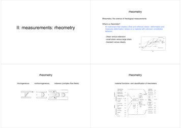
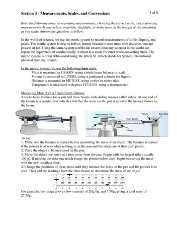
EE6404MEASUREMENTS&INSTRUMENTATIONSensitivity:The sensitivity denotes the smallest change in the measured variable to whichthe instrument responds. It is defined as the ratio of the changes in theoutput of an instrument to a change in the value of the quantity to be measured.Mathematically it is expressed as,OutputqoqoqoqiqiInput, qiInput, qiInfinitesimal change in outputSensitivity Infinitesimal change in inputǻqo ǻqiThus, if the calibration curve is liner, as shown, the sensitivity of the instrument is theslope of the calibration curve.If the calibration curve is not linear as shown, then the sensitivity varies with theinput.Inverse sensitivity or deflection factor is defined as the reciprocal of sensitivity.Inverse sensitivity or deflection factor 1/ sensitivityǻqi ǻqoLinearity:The linearity is defined as the ability to reproduce the input characteristicssymmetrically & linearly.The curve shows the actual calibration curve & idealized straight line.SCEEEE10Department of
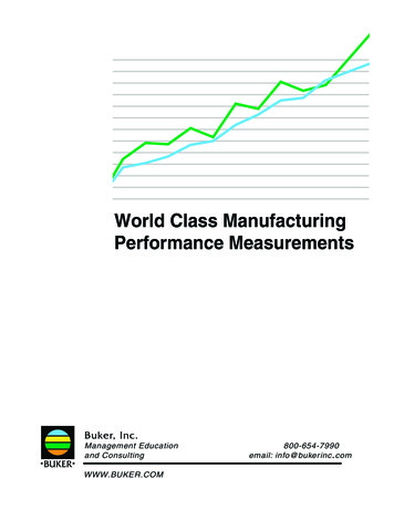
t lineOutputActualCurvemaximum deviationInputMax. deviation of output from idealized straight line% non-linearity Full scale readingReproducibility:It is the degree of closeness with which a given value may be repeatedlymeasured. It is specified in terms of scale readings over a given period of time.Repeatability:It is defined as the variation of scale reading & random in nature.Drift:Drift may be classified into three categories:a) zero drift:If the whole calibration gradually shifts due to slippage, permanent set,or due to undue warming up of electronic tube circuits, zero drift sets in.Characteristics withzero driftOutputOutputSpan nputInput(Fig) span driftSCEEEE(fig) zero drif11Department of
EE6404MEASUREMENTS&INSTRUMENTATIONb) span drift or sensitivity driftIf there is proportional change in the indication all along the upward scale, thedrifts is called span drift or sensitivity drift.c) Zonal drift:In case the drift occurs only a portion of span of an instrument, it is called zonaldrift.Resolution:If the input is slowly increased from some arbitrary input value, it will again be found thatoutput does not change at all until a certain increment is exceeded.This increment is called resolution.Threshold:If the instrument input is increased very gradually from zero there will be some minimumvalue below which no output change can be detected. Thisminimum value defines the threshold of the instrument.Stability:It is the ability of an instrument to retain its performance throughout is specified operatinglife.Tolerance:The maximum allowable error in the measurement is specified in terms of some value which iscalled tolerance.Rangeorspan:The minimum & maximum values of a quantity for which an instrument is designed tomeasure is called its range or span.Dynamic characteristics:The set of criteria defined for the instruments, which are changes rapidly with time, is called‘dynamic characteristics’.The various static characteristics are:i)Speed of response ii) Measuringlagiii)Fidelityiv)Dynamic errorSpeedofresponse:It is defined as the rapidity with which a measurement system responds to changes in themeasured quantity.SCE12Department of EEE
EE6404MEASUREMENTS&INSTRUMENTATIONMeasuringlag:It is the retardation or delay in the response of a measurement system to changes in themeasured quantity. The measuring lags are of two types:a) Retardation type:In this case the response of the measurement system begins immediately after thechange in measured quantity has occurred.b) Time delay lag:In this case the response of the measurement system begins after a dead time after theapplication of the input.Fidelity:It is defined as the degree to which a measurement system indicates changes in themeasurand quantity without dynamic error.Dynamicerror:It is the difference between the true value of the quantity changing with time & the valueindicated by the measurement system if no static error is assumed. It is also called measurementerror.1.3 ERRORS IN MEASUREMENTThe types of errors are followsi)Gross errorsii)Systematic errorsiii)Random errorsGrossErrors:The gross errors mainly occur due to carelessness or lack of experience of a humanbeginThese errors also occur due to incorrect adjustments of instrumentsThese errors cannot be treated mathematicallyThese errors are also called¶ personal errors’.Waystominimizegrosserrors:The complete elimination of g r o s s errors is not possible but one c a n minimize them bythe following ways:Taking great care while taking the reading, recording the r e a d i n g &calculating the resultWithout depending on only one reading, at least three or more readings must be taken *preferably by different persons.SCE13Department of EEE
:A constant uniform deviation of the operation of an instrument is known as a SystematicerrorThe Systematic errors are mainlydue to the short comings of the instrument & thecharacteristics of the material use d in the instrument, such a s defective or worn parts,ageing effects, env ironmental effects, etc.TypesofSystematicerrors:There are three types of Systematic errors as:i)Instrumental errorsii)Environmental errors iii)Observational errorsInstrumentalerrors:These errors can be mainly due to the following three reasons:a) Shortcomingsofinstruments:These are because of the mechanical structure of the instruments. For example frictionin the bearings of various moving parts; irregular spring tensions,reductions indue toimproper handling , hysteresis, gear backlash, stretching of spring, variations in air gap, etc .,Waystominimizethiserror:These errors can be avoided by the following methods:Selecting a proper instrument and planning the proper procedure for themeasurement recognizing the effect of sucherrors a n d applying t h e proper correctionfactors calibrating the instrument carefully against a standardb) Misuseofinstruments:A good instrument if used in abnormal way gives misleading results. Poor initial adjustment,Improper zero setting, using leads of high resistance etc., are the examples of misusing a goodinstrument. Such things do not cause the permanent damage to the instruments but definitelycause the serious errors.C) LoadingeffectsLoading effects due to im proper way of using the instrument cause the serious errors.The best ex ample of such loading effect error is connecting a w ell calibrated volt meter acrossthe two points of high resistance circuit. The same volt meter connected in a low resistance circuitgives accurate reading.SCE14Department of EEE
iserror:Thus the err ors due to the loading effect can be avoided by using an instrumentintelligently and correctly.Environmentalerrors:These errorsare due to the conditions external to the measuring instrument. The variousfactors resulting these environmentalerrors are temperature changes, pressure changes, thermalemf, ageing of equipment and frequency sensitivity of an instrument.Waystominimizethiserror:The various methods which can be used to reduce these errors are:i)ii)iii)iv)v)Using the proper correction factors and using the information supplied by themanufacturer of the instrumentUsing the arrangement which will keep the surrounding conditionsConstantReducing the effect of dust ,humidity on the components by hermetically sealing thecomponents in the instrumentsThe effects of external f i e l d s can be minimized by using the magnetic or electrostatic shields or screensUsing the equipment which is immune to such environmental effects.Observationalerrors:These are the errors introduced by the observer.These are many sources of observational errors such as parallax error while reading ameter, wrong scale selection, etc.WaystominimizethiserrorTo eliminate such errors one should use the instruments with mirrors, knife edgedpointers, etc.,The systematic errors can be subdivided as static and dynamic errors. The static errors arecaused by the limitations of the measuring device while the dynamic errors are caused by t h einstrument not responding fast enough to follow the changes in the variable to be measured.Randomerrors:Some errors still result, though the systematic and instrumental errors are reduced oratleast accounted for.The causes of such errors are unknown and hence the errors are calledrandom errors.SCE15Department of EEE
iserrorThe only way to reduce these errors i s by increasing t h e number of observations andusing the statistical methods toobtain the bestapproximation of the reading.1.4 STATISTICAL EVALUATION OF MEASUREMENT DATAOut of the various possible errors, the random errors cannot be determined in theordinary process of measurements. Such errors are treated mathematicallyThe mathematical analysis of the various measurements is calledstatistical analysis of the data’.For such statistical analysis, the same reading is taken number of times, g enerally u singdifferent observers, different instruments & by different ways of measurement. The statisti al aalysis helps to determine anal ytically t he uncert ainty of the final test results.Arithmeticmean&median:When the n umber of readings of the same measurement are taken, the mostlikely value from the set of measured value is the arithmetic mean of the number ofreadings taken.The arithmetic mean value can be mathematically obtained as,X1X 2 .Xn nThis mean is very close to true value, if number of readings is very large.But when the number of readings is large, calculation of mean value iscomplicated. In such a case, a median value is obtained which is obtained which is aclose approximation to the arithmetic mean value. For a set of µ Q¶ measurements X1, X2,X3.Xn written down in the ascending order of magnitudes, the median value is given by,X Xmedian X (n 1)/2Averagedeviation:The deviation tells us about the departure of a given reading from the arithmetic mean of thedata setdi xi- XWheredi deviation of ith readingXi value of ith readingX arithmetic meanThe average deviation is defined as the sum of the absolute values ofdeviations divided by the number of readings. This is also called mean deviationSCE16Department of EEE
EE6404MEASUREMENTS&INSTRUMENTATION1.5 STANDARD & CALIBRATIONCALIBRATIONCalibration is the process of making an adjustment or marking a scale so that thereadings of an instrument agree with the accepted & the certified standard.In other words, it is the procedure for determining the correct values of measurand bycomparison with the measured or standard ones.The calibration offers a guarantee to the device or instrument that it is operating withrequired accuracy, under stipulated environmental conditions.The calibration procedure involves the steps like visual inspection for various defects,installation according to the specifications, zero adjustment etc.,The calibration is the procedure for determining the correct values of measurand bycomparison with standard ones. The standard of device with which comparison is made is called astandard instrument. The instrument which is unknown & is to be calibrated is called testinstrument. Thus in calibration, test instrument is compared with standard instrument.Typesofcalibrationmethodologies:There are two methodologies for obtaining the comparison between test instrument &standard instrument. These methodologies arei)ii)Direct comparisonsIndirect comparisonsDirectcomparisons:In a direct comparison, a source or generator applies a known input to the meter under test.The ratio of what meter is indicating & the known generator values gives the meter¶ s error.In such case the meter is the test instrument while the generator is the standard instrument.The deviation of meter from the standard value is compared with the allowableperformance limit.With the help of direct comparison a generator or source also can be calibrated.SCE17Department of EEE
ons:In the indirect comparison, the test instrument is compared with the responsestandard instrument of same type i .e., if test instrument is meter, standardinstrument is also meter, if test instrument is generator; the standardinstrument is also generator & so on.If the test instrument is a meter then the same input is applied to the testmeter as well a standard meter.In case of generator calibration, the output of the generator tester as well asstandard, or set to same nominal levels.Then the transfer meter is used which measures the outputs of bothstandard and test generator.StandardAll the instruments are calibrated at the time of manufacturer againstmeasurement standards.A standard of measurement is a physical representation of a unit ofmeasurement.A standard means known accurate measure of physical quantity.The different size of standards of measurement are classified as i)International standardsii)iii)iv)Primary standardsSecondary standardsWorking standardsInternationalstandardsInternational standards are defined as the international agreement. Thesestandards,as mentioned above are maintained at the international bureau ofweights an d measures and are periodically evaluated and checked byabsolute measurements in term s of fundamental units of physics.These international standards are not available to the ordinary users for thecalibration purpose.For the improvements in the accuracy of absolute measurements theinternational units are replaced by the absolute units in 1948.Absolute units are more accurate than the international units.PrimarystandardsThese are highly accurate absolute standards, w hich can be used as ultimatereference standards.These primary standards are maintained at nationalSCEEEE18Department of
EE6404MEASUREMENTS&INSTRUMENTATIONstandard laboratories in different countries.These standards representing fundamental units as well as some electricaland mechanical derived units are calibrated independently by absolutemeasurements at each of the national laboratories.These are not available for use, outside the national laboratories.The main function ofthe primary standards is the calibration andverification of secondary standards.SecondarystandardsAs mentioned above, the primary standards are not ava ilable for use outsidethe national laboratories.The various industries need some reference standards. So, to protect highlya c c u r a t e p r i m a r y s t a n d a r d s t h e secondary s t a n d a r d s aremaintained, which are designed and constructed from the absolute standards.These are used by themeasurement and calibration laboratories inindustries and are maintained by the particular industry to which theybelong. Each industry has its own standards.WorkingstandardsThese are the basic tools of a measurement laboratory and are used to check and calibrate the instruments used in laboratory for accuracy and theperformance.International standardsNational standardlaboratories.Industries & secondarylaboratoriesMeasurement laboratoryProcess instrumentSCEEEE19Department of
EE6404MEASUREMENTS&INSTRUMENTATIONUNIT II ELECTRICAL AND ELECTRONICS INSTRUMENTS2.1 Principle And Types Of Analog And Digital VoltmetersØ Basically an electrical indicating instrument is divided into two types. They are i)Analog instrumentsii) Digital Instruments.Ø Analog instruments are nothing but its output is the deflection of pointer, which isproportional to its input.Ø Digital Instruments are its output is in decimal form.Ø Analog ammeters and voltmeters are classed together as there are no fundamentaldifferences in their operating principles.Ø The action of all ammeters and voltmeters, with the exception of electrostatictype of instruments, depends upon a deflecting torqueproduced by an electric current.Ø In an ammeter this torque is produced by a current to be measured or by a definitefraction of it.Ø In a voltmeter this torque is produced by a current which is proportional to thevoltage to be measured.Ø Thus all analog voltmeters and ammeters are essentially current measuringdevices.The essential requirements of a measuring instrument are(i)That its introduction into the circuit, where measurements are to be made,does not alter the circuit conditions ;(ii)The power consumed by them for their operation is small.1.2Ammeters & MultimetersAmmeters are connected in seriesIn the circuit whose current is to be measured. The power loss in an ammeter is I2Rawhere I is the current to be measured and R is the resistance of ammeter. Therefore, ammetersshould have a low electrical resistance so that they cause a small voltage drop and consequentlyabsorb small power.Voltmeters are connected in parallel with the circuit whose voltage is to be measured.The power loss in voltmeters is V where V is the voltage U) be measured and R is theresistance of voltmeter. The voltmeters should have a high electrical resistance, in orderthat the current drawn by them is small and consequently the power consumed is small.Types of instrumentsThe main types of instruments used as an ammeters and voltmeters are(i)Permanent magnet moving coil (PMMC)(ii) Moving iron(iii) Electro-dynamometer(iv) Hot wire(iv) Thermocouple(vi) Induction(vii) ElectrostaticSCE20Dept.of EEE
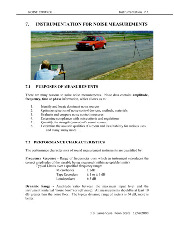
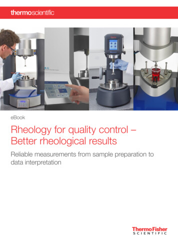
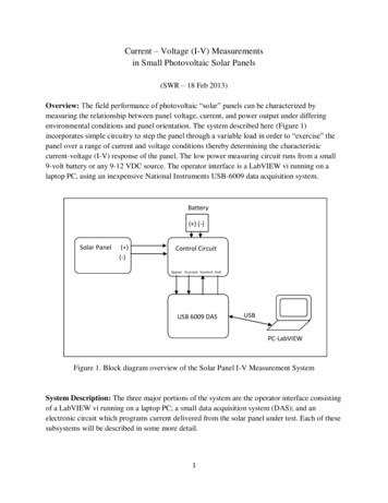
Permanent Magnet Moving Coil Instrument (PMMC)The permanent magnet moving coil instrument is the most accurate type for d.c.measur ements. The w orking pr inciple of these instrum ents i s the same as that of the d’Arsonval type of galvanometers, the difference being that a direct reading instrument isprovided with a pointer and a scale.(Fig) Permanent magnet moving coil instrumentSCE21Dept.of EEE
EE6404MEASUREMENTS&INSTRUMENTATIONConstruction of PMMC InstrumentsØ The constructional features of this instrument are shown in Fig.Ø The moving coil is wound with m any turns of enameled or silk coveredcopper wire.Ø The coil is mounted on a rectangular aluminium former which is pivoted onjewelled bearings.Ø The coils move freely in the field of a permanent magnet.Ø Most vol tmeter coils are w ound on m etal frames to provide the re quiredelectro-magnetic damping.Ø Most a mmeter coi ls, however, arewound on non -magnetic formers,because coil turns are effectively shorted by the ammeter shunt.Ø The coil itself, therefore, provides electro magnetic damping.Magnet SystemsØ Old style m agnet syste m consisted of relatively long U shapedpermanent magnets having soft iron pole pieces.ØOwing to development of materials likeAlcomax and Alnico,which have a h igh co -ercive force, i t is possible to use smaller magnetlengths and high field intensities.Ø The flux densities used in PMIMC i nstruments vary from 0.1 W b/m to 1Wb/m.ControlØ When the coil is suppo rted between tw o jewel bearings th e cont rol torqueis provided by two phosphor bronze hair springs.Ø These sprin gs also serve to lead c urrent in and o ut of the coil. The controltorque is provided by the ribbon suspension as shown.Ø This m ethod i s com parativelynew and is claimed to beadvantageous as it eliminates bearing friction.DampingØDamping torque is produced by movement of the aluminium formermoving in the magnetic field of the permanent magnet.Pointer and ScaleØ The pointer is carried by the spin dle and moves over a graduate d scale.Ø The poin ter is of lig ht-weight constructi on
EE6404 MEASUREMENTS&INSTRUMENTATION SCE 1 Department of EEE A Course Material on Measurements and Instrumentation By Mr.N.Kannapiran ASSISTANT PROFESSOR DEPARTMENT OF ELECTRONICS AND COMMUNICATION ENGINEERING SASURIE COLLEGE OF ENGINEERING . For contr