Transcription
CLASS NOTES ON ELECTRICAL MEASUREMENTS & INSTRUMENTATION2015CLASS NOTES ONELECTRICAL MEASUREMENTS & INSTRUMENTATIONFOR5TH & 6TH SEMESTER OFELECTRICAL ENGINEERING & EEE (B.TECH PROGRAMME)DEPARTMENT OF ELECTRICAL ENGINEERINGVEER SURENDRA SAI UNIVERSITY OF TECHNOLOGYBURLA -768018, ODISHA, INDIA1
CLASS NOTES ON ELECTRICAL MEASUREMENTS & INSTRUMENTATION2015DISCLAIMERThis document does not claim any originality and cannot be used as a substitute for prescribedtextbooks. The matter presented here is prepared by the author for their respective teachingassignments by referring the text books and reference books. Further, this document is notintended to be used for commercial purpose and the committee members are not accountable forany issues, legal or otherwise, arising out of use of this document.2
CLASS NOTES ON ELECTRICAL MEASUREMENTS & INSTRUMENTATION2015SYLLABUSELECTRICAL MEASUREMENTS & INSTRUMENTATION (3-1-0)MODULE-I (10 HOURS)Measuring Instruments: Classification, Absolute and secondary instruments, indicating instruments,control, balancing and damping, constructional details, characteristics, errors in measurement, Ammeters,voltmeters: (DC/AC) PMMC, MI, Electrodynamometer typeWattmeters: Electrodynamometer type, induction type, single phase and three phase wattmeter,compensation, Energymeters: AC. Induction type siqgle phase and three phase energy meter,compensation, creep, error, testing, Frequency Meters: Vibrating reed type, electrical resonance typeMODULE-II (10 HOURS)Instrument Transformers: Potential and current transformers, ratio and phase angle errors, phasordiagram, methods of minimizing errors; testing and applications.Galvanometers: General principle and performance equations of D' Arsonval Galvanometers, VibrationGalvanometer and Ballistic Galvanometer.Potentiometers: DC Potentiometer, Crompton potentiometer, construction, standardization, application.AC Potentiometer, Drysdale polar potentiometer; standardization, application.MODULE-III (10 HOURS)DC/AC Bridges :General equations for bridge balance, measurement of self inductance by Maxwell’sbridge (with variable inductance & variable capacitance), Hay’s bridge, Owen’s bridge, measurement ofcapacitance by Schearing bridge, errors, Wagner’s earthing device, Kelvin’s double bridge.Transducer: Strain Gauges, Thermistors, Thermocouples, Linear Variable Differential Transformer(LVDT), Capacitive Transducers, Peizo-Electric transducers, Optical Transducer, Torque meters,inductive torque transducers, electric tachometers, photo-electric tachometers, Hall Effect TransducerMODULE-IV (10 HOURS)CRO: Block diagram, Sweep generation, vertical amplifiers, use of CRG in measurement of frequency,phase, Amplitude and rise time of a pulse.Digital Multi-meter: Block diagram, principle of operation, Accuracy of measurement, ElectronicVoltmeter: Transistor Voltmeter, Block diagram, principle of operation, various types of electronicvoltmeter, Digital Frequency meter: Block diagram, principle of operationTEXT BOOKS[1]. A Course in Elec. & Electronics Measurements & Instrumentation: A K. Sawhney[2]. Modern Electronic Instrumentation and Measurement Techniques: Helfrick & Cooper[3]. Electrical Measurement and Measuring Instruments - Golding & Waddis3
CLASS NOTES ON ELECTRICAL MEASUREMENTS & INSTRUMENTATION2015Model Question Paper: Set-1Full Marks: 70Time: 3 hoursAnswer any six questions including question No. 1 which is compulsory.The figures in the right-hand margin indicate marks.(Answer any six questions including Q.No. 1)[2X10]1. Answer the following questions:(a) Differentiate between the spring control and gravity control.(b) Why an ammeter should have a low resistance value.(c) What are the precautions taken while using a DC voltmeter and DC ammeter.(d) What is the major cause of creeping error in an energy meter(e) What are the errors occurs in instrument transformers.(f) Differentiate the principle of dc potentiometer and ac potentiometer.(g) What are the sources of errors in AC bridge measurement.(h) Differentiate between dual trace and dual beam CRO.(i) What are active and passive transducers? Give examples.(j) What is piezoelectric effect.2. (a) With a neat diagram explain in detail the construction of PMMC instrument.(b)What are the shunts and multiplier? Derive the expression for both, with reference tometers used in electrical circuits.[5 5]3. (a) Discuss with block diagram, the principle of operation of single phase energy meter.(b) An energy meter is designed to make 100 revolutions of the disc for one unit ofenergy. Calculate the number of revolutions made by it , when connected to a loadcarrying 40 A at 230V and 0.4 p.f. for 1 hour. If it actually makes 360 revolutions, findthe percentage error.[5 5]4. (a) Derive expression for actual transformation ratio, ratio error and phasor angle error ofa P.T.(b) A current transformer with bar primary has 300 turns in its secondary winding. Theresistance and reactance of the secondary circuit are 1.5Ω and 1.0 Ω respectively,including the transformer winding. With 5A flowing in the secondary winding, themagnetizing mmf is 100AT and the core loss is 1.2 W. Determine the ratio and phaseangle errors.[5 5]5. (a) Derive the equation of balance for Anderson bridge and also draw the phasor diagram.(b) An AC bridge is balanced at 2KHz with the following components in each arm:Arm AB 10KΩ, Arm BC 100µF in series with 100KΩ, Arm AD 50KΩFind the unknown impendence R jX in the arm DC, if the detector is between BD.6. (a) What is transducer? Briefly explain the procedure for selecting a transducer.(b) Derive an expression for gauge factor in terms of Poission’s ration.[5 5]7. (a) With a block diagram, explain the working of CRO(b) With a block diagram, explain in detail the digital frequency meter[5 5]8. Write short notes on(a) Kelvin’s double bridge(b) D- Arsonaval galvanometer[5 5]4
CLASS NOTES ON ELECTRICAL MEASUREMENTS & INSTRUMENTATION2015Model Question Paper: Set-2Full Marks: 70Time: 3 hoursAnswer any six questions including question No. 1 which is compulsory.The figures in the right-hand margin indicate marks.(Answer any six questions including Q.No. 1)[2X10]Q.1 Answer the following questions:(a) Why is damping required for an electromechanical measuring instrument?(b) Why is scale of MI instrument calibrated non- linearly?(c) What is the difference between analog and digital frequency meter?(d) Which instrument can be used to measure non-sinusoidal voltage?(e) What is the major cause of creeping error in an energy meter?(f) What do you mean by active and passive transducer? Give suitable examples.(g) Draw a suitable AC bridge used for measurement of frequency.(h) What are the steps to be taken for minimizing errors in PT?(i) Discuss briefly the role of ordinary galvanometer?(j) What is the function of time base generator in CRO?Q.2 (a) Derive the torque equation of a moving iron instrument?(b) Sketch and explain the working of moving-coil instrument.[5][5]Q.3 (a) Discuss a method for measurement of low resistance.(b) Explain the operation of a Wagner’s earthing device.[5][5]Q.4 Derive the errors of CT and PT, and discuss its preventives.[10]Q.5 (a) Discuss about a ac bridge used for measurement of capacitance(b) Discuss about a galvanometer which is used for measurement of frequency.[5][5]Q.6 (a) How is the voltmeter calibrated with DC potentiometer ?(b) What is the use of LVDT? Discuss its basic principle of operation.[5][5]Q.7 (a) How are the frequency and phase measured in CRO.(b)Draw the block diagram of an electronic voltmeter and explain its operation.[5][5]8. Write short notes on any two:(a) Owen’s bridge(b)Digital frequency meter(c) Hall-effect transducer[5X2]5
CLASS NOTES ON ELECTRICAL MEASUREMENTS & INSTRUMENTATION2015Model Question Paper: Set-3Full Marks: 70Time: 3 hoursAnswer any six questions including question No. 1 which is compulsory.The figures in the right-hand margin indicate marks.(Answer any six questions including Q.No. 1)[2X10]1. Answer the following questions:(k) Why scales of the gravity control instruments are not uniform but are crowded?(l) Why eddy current damping cannot be used for moving iron instrument?(m) What is mean by Phantom Load?(n) Why do we use a multiplier with a voltmeter?(o) What is the major cause of creeping error in an energy meter?(p) Why is dynamometer type instrument chiefly used as a wattmeter?(q) Define gauge factor of a strain gauges how is it related to poisons ratio µ ?(r) Why the secondary of a CT is never left open circuited?(s) Why there are two conditions of balance in ac bridges, where as there is only one fordc bridges?(t) How to prevent the loading of a circuit under test when a CRO is used?2. (a) Draw the possible methods of connecting the pressure coil of a wattmeter andcompare the errors. Explain the meaning of ‘compensating winding’ in a wattmeter andshow how they help to reduce the error.[5](b) Sketch and explain the working of moving-coil instrument.[5]3. (a) What are the different testing conducted on a single phase energy meter?[5](b)The meter constant of 230V, 10A energy meter is 1700. The meter is tested under halfload and rated voltage at unity p.f. The meter is found to make 80 revolutions in 138 sec.Find % error.[5]4. Differentiate between a C.T. and P.T. Discuss the theory of a P.T with phasor diagrams.Derive expression for actual transformation ratio, ratio error and phasor angle error of aP.T.[10]5. (a) Describe how an AC potentiometer, can be used for the calibration of wattmeter? [5](b)Explain how LVDT can be used for measurement of displacement.[5]6. (a) Derive the equation of balance of a Schering Bridge. Draw the phasor diagram undernull conditions and explain how loss angle of capacitor can be calculated.[5](b) Describe the general working principle of a D’ Arsonval Galvanometer.[5]7.(a) Explain the use of CRG in the measurement of frequency.[5](b)Draw the block diagram of an electronic voltmeter and explain its operation. [5]8. Write short notes on:(a) Thermo couple(b)Peizo-Electric Transducers.[5X2]6
CLASS NOTES ON ELECTRICAL MEASUREMENTS & INSTRUMENTATION2015Model Question Paper: Set-4Full Marks: 70Time: 3 hoursAnswer any six questions including question No. 1 which is compulsory.The figures in the right-hand margin indicate marks.(Answer any six questions including Q.No. 1)1. Answer the following questions:[2 x 10](a) What are the parameters on which the critical damping of galvanometer depends?Why critical damping is important?(b) The current flowing through a resistance of 10.281 kΩ is measured as 1.217 mA.Calculate the voltage drop across the resistor to the appropriate number of significanterrors.(c) What are the main advantages and disadvantages of PMMC instruments?(d) Why an electrodynamometer type instrument is called a “Universal Instrument”?(e) Write the working principle of resonance type frequency meter.(f) What are the advantages of electronic voltmeter over electro – mechanical typevoltmeter?(g) Why Maxwell Bridge is limited to the measurement of medium – Q coils?(h) What will happen in a current transformer, if the secondary circuit is accidentallyopened while the primary winding is energized?(i) Suggest a transducer for the measurement of displacement in the order of one – tenthof millimeter and write the basic principle of measurement.(j) What is the function of delay line in oscilloscope?Q. 2.[5 5]a) The coil of a measuring instrument has a resistance of 1 Ω and the instrument has a fullscale deflection of 250 V when a resistance of 4999 Ω is connected with it. Find thecurrent range of the instrument when used as an ammeter with the coil connected across ashunt of (1/499) Ω and the value of the shunt resistance for the instrument to give a fullscale deflection of 50 A.b) Distinguish between gross error, systematic error and random error with examples. Whatare the methods for their elimination/reduction?Q. 3.[5 5]a) Draw the circuit diagram of Schering Bridge. Derive the conditions for balancing thebridge and draw the phasor diagram during balanced condition.b) Describe the theory and method of measurement of low resistance using Kelvin’s doubleBridge. How the effect of thermo – electric emf is taken into account duringmeasurement?7
CLASS NOTES ON ELECTRICAL MEASUREMENTS & INSTRUMENTATIONQ. 4.2015[10]A single range student type potentiometer has 20 step dial switch where each steprepresents 0.1 V. The dial resistors are 20 Ω. The slide wire of the potentiometer iscircular and has 10 turns and a resistance of 10 Ω each. The slide wire has 200 divisionsand interpolation can be done to one fourth of a division. The working battery has avoltage of 10 V and negligible internal resistance. Draw the circuit diagram and calculatei)The measuring range of potentiometerii)The resolutioniii)Working currentiv)Resistance of series rheostatQ. 5.[5 5]a) What is the requirement of “Screening of bridge components”? Draw the circuit diagramof Wagner’s earthing device and explain its operation.b) Define the sensitivity of a strain gauge. Draw the circuit for measurement of strain andderive the expression of output voltage in terms of strain.Q. 6.[5 5]a) Derive the torque equation of moving iron instrument and comment on the shape of thescale.b) Prove that for electrodynamometer type wattmetertrue power {cos Φ / [cos Φ cos (Φ – β]} x actual wattmeter readingWhere cos Φ power factor of the circuitβ tan-1 (ωL/R) where L and R are the inductance and resistance of the pressurecoil of the circuit.Q. 7.[5 5]a) Describe the construction and principle of operation of D’ Arsonval type Galvanometer.b) Discuss the major sources of errors in current transformer. What are the means to reduceerrors in CT? Explain design and constructional feature to reduce the error.Q. 8.[6 4]a) Describe the measurement of frequency, phase angle and time delay using oscilloscopewith suitable diagrams and mathematical expressions.b) With block diagram explain the operation of “Ramp type’ digital voltmeter.8
CLASS NOTES ON ELECTRICAL MEASUREMENTS & INSTRUMENTATION2015MEASURING INSTRUMENTS1.1 Definition of instrumentsAn instrument is a device in which we can determine the magnitude or value of thequantity to be measured. The measuring quantity can be voltage, current, power and energy etc.Generally instruments are classified in to two categories.InstrumentAbsolute InstrumentSecondary Instrument1.2 Absolute instrumentAn absolute instrument determines the magnitude of the quantity to be measured in terms of theinstrument parameter. This instrument is really used, because each time the value of themeasuring quantities varies. So we have to calculate the magnitude of the measuring quantity,analytically which is time consuming. These types of instruments are suitable for laboratory use.Example: Tangent galvanometer.1.3 Secondary instrumentThis instrument determines the value of the quantity to be measured directly. Generally theseinstruments are calibrated by comparing with another standard secondary instrument.Examples of such instruments are voltmeter, ammeter and wattmeter etc. Practicallysecondary instruments are suitable for measurement.Secondary instrumentsIndicating yIndicating instruments
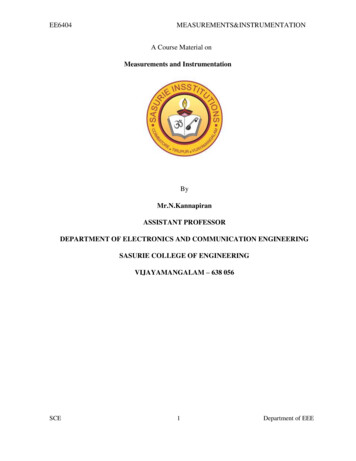
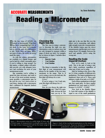
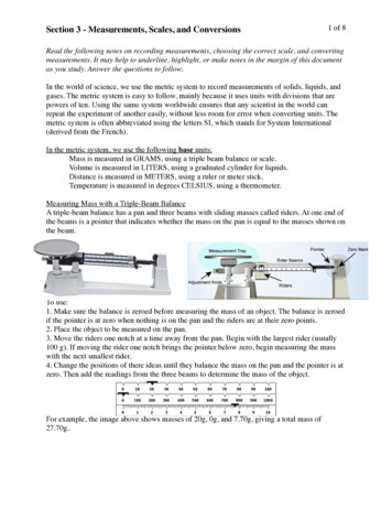
CLASS NOTES ON ELECTRICAL MEASUREMENTS & INSTRUMENTATION20151.3.1 Indicating instrumentThis instrument uses a dial and pointer to determine the value of measuring quantity. The pointerindication gives the magnitude of measuring quantity.1.3.2 Recording instrumentThis type of instruments records the magnitude of the quantity to be measured continuously overa specified period of time.1.3.3 Integrating instrumentThis type of instrument gives the total amount of the quantity to be measured over a specifiedperiod of time.1.3.4 Electromechanical indicating instrumentFor satisfactory operation electromechanical indicating instrument, three forces are necessary.They are(a) Deflecting force(b) Controlling force(c)Damping force1.4 Deflecting forceWhen there is no input signal to the instrument, the pointer will be at its zero position. To deflectthe pointer from its zero position, a force is necessary which is known as deflecting force. Asystem which produces the deflecting force is known as a deflecting system. Generally adeflecting system converts an electrical signal to a mechanical force.Fig. 1.1 Pointer scale10
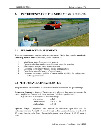
CLASS NOTES ON ELECTRICAL MEASUREMENTS & INSTRUMENTATION20151.4.1 Magnitude effectWhen a current passes through the coil (Fig.1.2), it produces a imaginary bar magnet. When asoft-iron piece is brought near this coil it is magnetized. Depending upon the current directionthe poles are produced in such a way that there will be a force of attraction between the coil andthe soft iron piece. This principle is used in moving iron attraction type instrument.Fig. 1.2If two soft iron pieces are place near a current carrying coil there will be a force of repulsionbetween the two soft iron pieces. This principle is utilized in the moving iron repulsion typeinstrument.1.4.2 Force between a permanent magnet and a current carrying coilWhen a current carrying coil is placed under the influence of magnetic field produced by apermanent magnet and a force is produced between them. This principle is utilized in the movingcoil type instrument.Fig. 1.31.4.3 Force between two current carrying coilWhen two current carrying coils are placed closer to each other there will be a force of repulsionbetween them. If one coil is movable and other is fixed, the movable coil will move away fromthe fixed one. This principle is utilized in electrodynamometer type instrument.11
CLASS NOTES ON ELECTRICAL MEASUREMENTS & INSTRUMENTATION2015Fig. 1.41.5 Controlling forceTo make the measurement indicated by the pointer definite (constant) a force is necessary whichwill be acting in the opposite direction to the deflecting force. This force is known as controllingforce. A system which produces this force is known as a controlled system. When the externalsignal to be measured by the instrument is removed, the pointer should return back to the zeroposition. This is possibly due to the controlling force and the pointer will be indicating a steadyvalue when the deflecting torque is equal to controlling torque.Td Tc(1.1)1.5.1 Spring controlTwo springs are attached on either end of spindle (Fig. 1.5).The spindle is placed in jewelledbearing, so that the frictional force between the pivot and spindle will be minimum. Two springsare provided in opposite direction to compensate the temperature error. The spring is made ofphosphorous bronze.When a current is supply, the pointer deflects due to rotation of the spindle. While spindle isrotate, the spring attached with the spindle will oppose the movements of the pointer. The torqueproduced by the spring is directly proportional to the pointer deflection θ .TC θ(1.2)The deflecting torque produced Td proportional to ‘I’. When TC Td , the pointer will come to asteady position. Thereforeθ I(1.3)12
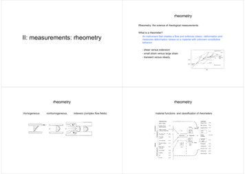
CLASS NOTES ON ELECTRICAL MEASUREMENTS & INSTRUMENTATION2015Fig. 1.5Since, θ and I are directly proportional to the scale of such instrument which uses springcontrolled is uniform.1.6 Damping forceThe deflection torque and controlling torque produced by systems are electro mechanical.Due to inertia produced by this system, the pointer oscillates about it final steady position beforecoming to rest. The time required to take the measurement is more. To damp out the oscillationis quickly, a damping force is necessary. This force is produced by different systems.(a) Air friction damping(b) Fluid friction damping(c) Eddy current damping1.6.1 Air friction dampingThe piston is mechanically connected to a spindle through the connecting rod (Fig. 1.6). Thepointer is fixed to the spindle moves over a calibrated dial. When the pointer oscillates inclockwise direction, the piston goes inside and the cylinder gets compressed. The air pushes thepiston upwards and the pointer tends to move in anticlockwise direction.13
CLASS NOTES ON ELECTRICAL MEASUREMENTS & INSTRUMENTATION2015Fig. 1.6If the pointer oscillates in anticlockwise direction the piston moves away and the pressure of theair inside cylinder gets reduced. The external pressure is more than that of the internal pressure.Therefore the piston moves down wards. The pointer tends to move in clock wise direction.1.6.2 Eddy current dampingFig. 1.6 Disc typeAn aluminum circular disc is fixed to the spindle (Fig. 1.6). This disc is made to move in themagnetic field produced by a permanent magnet.14
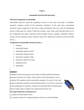
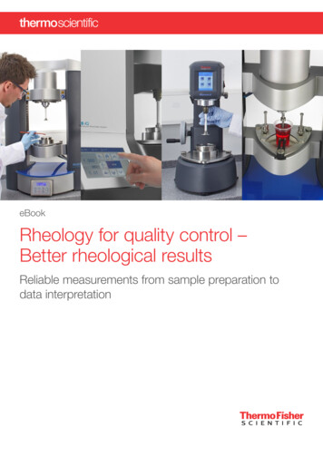
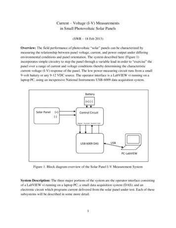
CLASS NOTES ON ELECTRICAL MEASUREMENTS & INSTRUMENTATION2015When the disc oscillates it cuts the magnetic flux produced by damping magnet. An emf isinduced in the circular disc by faradays law. Eddy currents are established in the disc since it hasseveral closed paths. By Lenz’s law, the current carrying disc produced a force in a directionopposite to oscillating force. The damping force can be varied by varying the projection of themagnet over the circular disc.Fig. 1.6 Rectangular type1.7Permanent Magnet Moving Coil (PMMC) instrumentOne of the most accurate type of instrument used for D.C. measurements is PMMC instrument.Construction: A permanent magnet is used in this type instrument. Aluminum former isprovided in the cylindrical in between two poles of the permanent magnet (Fig. 1.7). Coils arewound on the aluminum former which is connected with the spindle. This spindle is supportedwith jeweled bearing. Two springs are attached on either end of the spindle. The terminals of themoving coils are connected to the spring. Therefore the current flows through spring 1, movingcoil and spring 2.Damping: Eddy current damping is used. This is produced by aluminum former.Control: Spring control is used.15
CLASS NOTES ON ELECTRICAL MEASUREMENTS & INSTRUMENTATION2015Fig. 1.7Principle of operationWhen D.C. supply is given to the moving coil, D.C. current flows through it. When the currentcarrying coil is kept in the magnetic field, it experiences a force. This force produces a torqueand the former rotates. The pointer is attached with the spindle. When the former rotates, thepointer moves over the calibrated scale. When the polarity is reversed a torque is produced in theopposite direction. The mechanical stopper does not allow the deflection in the oppositedirection. Therefore the polarity should be maintained with PMMC instrument.If A.C. is supplied, a reversing torque is produced. This cannot produce a continuous deflection.Therefore this instrument cannot be used in A.C.Torque developed by PMMCLetTd deflecting torqueTC controlling torqueθ angle of deflectionK spring constantb width of the coil16
CLASS NOTES ON ELECTRICAL MEASUREMENTS & INSTRUMENTATION2015l height of the coil or length of coilN No. of turnsI currentB Flux densityA area of the coilThe force produced in the coil is given byF BIL sin θ(1.4) When θ 90For N turns, F NBIL(1.5)Torque produced Td F r distance(1.6)Td NBIL b BINA(1.7)Td BANI(1.8)Td I(1.9)AdvantagesTorque/weight is highPower consumption is lessScale is uniformDamping is very effectiveSince operating field is very strong, the effect of stray field is negligibleRange of instrument can be extendedDisadvantagesUse only for D.C.Cost is highError is produced due to ageing effect of PMMCFriction and temperature error are present17
CLASS NOTES ON ELECTRICAL MEASUREMENTS & INSTRUMENTATION20151.7.1 Extension of range of PMMC instrumentCase-I: ShuntA low shunt resistance connected in parrel with the ammeter to extent the range of current. Largecurrent can be measured using low current rated ammeter by using a shunt.Fig. 1.8Let Rm Resistance of meterRsh Resistance of shuntI m Current through meterI sh current through shuntI current to be measure Vm Vsh(1.10)I m Rm I sh RshI m Rsh I sh Rm(1.11)Apply KCL at ‘P’ I I m I sh(1.12)Eqn (1.12) by I mII 1 shImIm(1.13)18
CLASS NOTES ON ELECTRICAL MEASUREMENTS & INSTRUMENTATION2015IR 1 mImRsh(1.14) R I I m 1 m Rsh (1.15) R 1 m is called multiplication factor Rsh Shunt resistance is made of manganin. This has least thermoelectric emf. The change isresistance, due to change in temperature is negligible.Case (II): MultiplierA large resistance is connected in series with voltmeter is called multiplier (Fig. 1.9). A largevoltage can be measured using a voltmeter of small rating with a multiplier.Fig. 1.9LetRm resistance of meterRse resistance of multiplierVm Voltage across meterVse Voltage across series resistanceV voltage to be measuredI m I se(1.16)Vm Vse Rm Rse(1.17)VR se seVm Rm(1.18)19
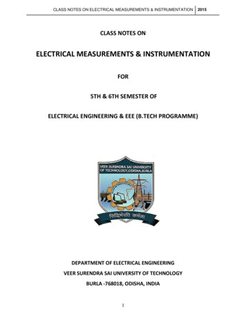
CLASS NOTES ON ELECTRICAL MEASUREMENTS & INSTRUMENTATIONApply KVL, V Vm Vse2015(1.19)Eqn (1.19) Vm R VV 1 se 1 se VmVm Rm (1.20) R V Vm 1 se Rm (1.21) Rse 1 Multiplication factorRm 1.8 Moving Iron (MI) instrumentsOne of the most accurate instrument used for both AC and DC measurement is moving ironinstrument. There are two types of moving iron instrument. Attraction type Repulsion type1.8.1 Attraction type M.I. instrumentConstruction: The moving iron fixed to the spindle is kept near the hollow fixed coil (Fig. 1.10).The pointer and balance weight are attached to the spindle, which is supported with jeweledbearing. Here air friction damping is used.Principle of operationThe current to be measured is passed through the fixed coil. As the current is flow through thefixed coil, a magnetic field is produced. By magnetic induction the moving iron gets magnetized.The north pole of moving coil is attracted by the south pole of fixed coil. Thus the deflectingforce is produced due to force of attraction. Since the moving iron is attached with the spindle,the spindle rotates and the pointer moves over the calibrated scale. But the force of attractiondepends on the current flowing through the coil.Torque developed by M.ILet ‘ θ ’ be the deflection corresponding to a current of ‘i’ ampLet the current increases by di, the corresponding deflection is ‘ θ dθ ’20
CLASS NOTES ON ELECTRICAL MEASUREMENTS & INSTRUMENTATION2015Fig. 1.10There is change in inductance since the position of moving iron change w.r.t the fixedelectromagnets.Let the new inductance value be ‘L dL’. The current change by ‘di’ is dt seconds.Let the emf induced in the coil be ‘e’ volt.e ddidL( Li ) L idtdtdt(1.22)Multiplying by ‘idt’ in equation (1.22)e idt LdidL idt i idtdtdt(1.23)e idt Lidi i 2 dL(1.24)Eqn (1.24) gives the energy is used in to two forms. Part of energy is stored in the inductance.Remaining energy is converted in to mechanical energy which produces deflection.Fig. 1.1121
CLASS NOTES ON ELECTRICAL MEASUREMENTS & INSTRUMENTATION2015Change in energy stored Final energy-initial energy stored 11( L dL)(i di) 2 Li 2221 {( L dL)(i 2 di 2 2idi) Li 2 }21 {( L dL)(i 2 2idi) Li 2 }21 {Li 2 2 Lidi i 2 dL 2ididL Li 2 }21 {2 Lidi i 2 dL}21 Lidi i 2 dL2(1.25)Mechanical work to move the pointer by dθ Td dθBy law of conservation of energy,Electrical energy supplied Increase in stored energy mechanical work done.Input energy Energy stored Mechanical energy1Lidi i 2 dL Lidi i 2 dL Td dθ2(1.26)(1.27)1 2i dL Td dθ2(1.28)1 dLTd i 22 dθ(1.29)At steady state condition Td TC1 2 dLi Kθ2 dθ(1.30)1 2 dLi2 K dθ(1.31)θ θ i2(1.32)When the instruments measure AC, θ i 2 rmsScale of the instrument is non uniform.22
CLASS NOTES ON ELECTRICAL MEASUREMENTS & INSTRUMENTATION2015AdvantagesMI can be used in AC and DCIt is cheapSupply is given to a fixed coil, not in moving coil.Simple constructionLess friction error.DisadvantagesIt suffers from eddy current and hysteresis errorScale is not uniformIt consumed more powerCalibration is different for AC and DC operation1.8.2 Repulsion type moving iron instrumentConstruction: The repulsion type instrument has a hollow fixed iron attached to it (Fig. 1.12).The moving iron is connected to the spindle. The pointer is also attached to the spindle insupported with jeweled bearing.Principle of operation: When the current flows through the coil, a magnetic field is produced byit. So both fixed iron and moving iron are magnetized with the same polarity, since they are keptin the same magnetic field. Similar poles of fixed and moving iron get repelled. Thus thedeflecting torque is produced due to magnetic repulsion. Since moving iron is attached tospindle, the spindle will move. So that pointer moves over the calibrated scale.Damping: Air friction damping is used to reduce the oscillation.Control: Spring control is used.23
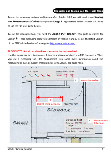
CLASS NOTES ON ELECTRICAL MEASUREMENTS & INSTRUMENTATIONFig. 1.121.9 Dynamometer (or) Electromagnetic moving coil instrument (EMMC)Fig. 1.13242015
CLASS NOTES ON ELECTRICAL MEASUREMENTS & INSTRUMENTATION2015This instrument can be used for the measurement of voltage, current and power. The differencebetween the PMMC and dynamometer type instrument is that the permanent magnet is replacedby an electromagnet.Construction: A fixed coil is divided in to two equal half. The moving coil is placed between thetwo half of the fixed coil. Both the fixed and moving coils are air cored. So that the hysteresiseffect will be zero. The pointer is attached with the spindle. In a non metallic former the movingcoil is wounded.Control: Spring control is used.Damping: Air friction damping is used.Principle of operation:When the current flows through the fixed coil, it produced a magnetic field, whose flux density isproportional to the current through the fixed coil. The moving coil is kept in between the fixedcoil. When the current passes through the moving coil, a magnetic field is produced by this coil.The magnetic poles are produced in such a way that the torque produced on the moving c
ELECTRICAL MEASUREMENTS & INSTRUMENTATION (3-1-0) MODULE-I (10 HOURS) Measuring Instruments: Classification, Absolute and secondary instruments, indicating instruments, control, balancing and damping, constructional details, characteristics, errors in measurement, Ammete