Transcription
842E-CM Integrated Motion Encoder on EtherNet/IPUser Manual
Important User InformationSolid-state equipment has operational characteristics differing from those of electromechanical equipment.Safety Guidelines for the Application, Installation and Maintenance of Solid State Controls (publication SGIIN001 -EN-P available from your local Rockwell Automation sales office or online at http://www.rockwellautomation.com/literature/) describes some important differences between solid-stateequipment and hard-wired electromechanical devices. Because of this difference, and also because of the widevariety of uses for solid-state equipment, all persons responsible for applying this equipment must satisfythemselves that each intended application of this equipment is acceptable.In no event will Rockwell Automation, Inc. be responsible or liable for indirect or consequential damagesresulting from the use or application of this equipment.The examples and diagrams in this manual are included solely for illustrative purposes. Because of the manyvariables and requirements associated with any particular installation, Rockwell Automation, Inc. cannotassume responsibility or liability for actual use based on the examples and diagrams.No patent liability is assumed by Rockwell Automation, Inc. with respect to use of information, circuits,equipment, or software described in this manual.Reproduction of the contents of this manual, in whole or in part, without written permission of RockwellAutomation, Inc., is prohibited.Throughout this manual, when necessary, we use notes to make you aware of safety considerations.WARNING: Identifies information about practices or circumstances that can cause an explosion in a hazardous environment,which may lead to personal injury or death, property damage, or economic loss.ATTENTION: Identifies information about practices or circumstances that can lead to personal injury or death, propertydamage, or economic loss. Attentions help you identify a hazard, avoid a hazard, and recognize the consequence.SHOCK HAZARD: Labels may be on or inside the equipment, for example, a drive or motor, to alert people that dangerousvoltage may be present.BURN HAZARD: Labels may be on or inside the equipment, for example, a drive or motor, to alert people that surfaces mayreach dangerous temperatures.IMPORTANTIdentifies information that is critical for successful application and understanding of the product.Rockwell Automation, Allen-Bradley, CompactLogix, Kinetix, PanelView, POINT I/O, RSLinx, RSLogix, Stratix 5700, and Studio 5000 are trademarks of Rockwell Automation, Inc.Trademarks not belonging to Rockwell Automation are property of their respective companies.It is recommended that you save this user manual for future use.2Rockwell Automation Publication 842E-UM002A-EN-P - November 2013
Table of ContentsImportant User Information . . . . . . . . . . . . . . . . . . . . . . . . . . . . . . . . . . . . 2PrefaceWho Should Use This Manual . . . . . . . . . . . . . . . . . . . . . . . . . . . . . . . . . . .Purpose of This Manual . . . . . . . . . . . . . . . . . . . . . . . . . . . . . . . . . . . . . . . .Common Techniques Used in This Manual . . . . . . . . . . . . . . . . . . . . . .Requirements. . . . . . . . . . . . . . . . . . . . . . . . . . . . . . . . . . . . . . . . . . . . . . . . . .Components of an Integrated Motion Application . . . . . . . . . . . . . .Terminology . . . . . . . . . . . . . . . . . . . . . . . . . . . . . . . . . . . . . . . . . . . . . . . . . . .Related Documentation . . . . . . . . . . . . . . . . . . . . . . . . . . . . . . . . . . . . . . . .5556679Chapter 1Safety PrecautionsAuthorized Personnel . . . . . . . . . . . . . . . . . . . . . . . . . . . . . . . . . . . . . . . . .Correct Use . . . . . . . . . . . . . . . . . . . . . . . . . . . . . . . . . . . . . . . . . . . . . . . . . . .General Safety Notes and Protective Measures . . . . . . . . . . . . . . . . .Environmental Protection . . . . . . . . . . . . . . . . . . . . . . . . . . . . . . . . . . . . .11121213Chapter 2About the EncoderFeatures . . . . . . . . . . . . . . . . . . . . . . . . . . . . . . . . . . . . . . . . . . . . . . . . . . . . . .CIP Sync Overview. . . . . . . . . . . . . . . . . . . . . . . . . . . . . . . . . . . . . . . . .Typical Configurations . . . . . . . . . . . . . . . . . . . . . . . . . . . . . . . . . . . . . . . .Star Topology . . . . . . . . . . . . . . . . . . . . . . . . . . . . . . . . . . . . . . . . . . . . .Linear Topology . . . . . . . . . . . . . . . . . . . . . . . . . . . . . . . . . . . . . . . . . . .Device Level Ring Topology . . . . . . . . . . . . . . . . . . . . . . . . . . . . . . .151616171819Chapter 3InstallationMechanical . . . . . . . . . . . . . . . . . . . . . . . . . . . . . . . . . . . . . . . . . . . . . . . . . . .Shaft Rotation Direction . . . . . . . . . . . . . . . . . . . . . . . . . . . . . . . . . . .Mounting with a Solid Shaft . . . . . . . . . . . . . . . . . . . . . . . . . . . . . . .Mounting with a Hollow Shaft . . . . . . . . . . . . . . . . . . . . . . . . . . . . .Electrical. . . . . . . . . . . . . . . . . . . . . . . . . . . . . . . . . . . . . . . . . . . . . . . . . . . . . .Electrical Wiring Instructions . . . . . . . . . . . . . . . . . . . . . . . . . . . . . . .Pin Assignments. . . . . . . . . . . . . . . . . . . . . . . . . . . . . . . . . . . . . . . . . . .Functional Specifications . . . . . . . . . . . . . . . . . . . . . . . . . . . . . . . . . .2121212223232424Chapter 4Configuring the EncoderConfiguring the 842E-CM Encoder IP Address . . . . . . . . . . . . . . . . . .Ethernet Connection . . . . . . . . . . . . . . . . . . . . . . . . . . . . . . . . . . . . . .842E-CM Encoder Port Configuration . . . . . . . . . . . . . . . . . . . . . .Setting the IP Address. . . . . . . . . . . . . . . . . . . . . . . . . . . . . . . . . . . . . . . . .Assigning the Last Octet in an IP Address Scheme of192.168.1.xxx Using the Network Address Switches. . . . . . . . .Assigning the IP Address Using BootP/DHCP:. . . . . . . . . . . . . . .Rockwell Automation Publication 842E-UM002A-EN-P- November 20132525252526263
Table of ContentsChapter 5Example: Setting Up the Hardware. . . . . . . . . . . . . . . . . . . . . . . . . . . . . 29Configuring the 842E-CM EncoderChecking the Integration in EtherNet/IP via RSLinx Classic. . . 30Using the Logix Designer ApplicationAdding and Configuring the Add-on Profile in RSlogix 5000 . . . .Adding the Encoder to Your Logix Designer Project. . . . . . . . .Configuring the Encoder . . . . . . . . . . . . . . . . . . . . . . . . . . . . . . . . . . .Configuring the Motion Group . . . . . . . . . . . . . . . . . . . . . . . . . . . . .Configuring Axis Properties . . . . . . . . . . . . . . . . . . . . . . . . . . . . . . . .Testing the Axis . . . . . . . . . . . . . . . . . . . . . . . . . . . . . . . . . . . . . . . . . . . . . . .313133353644Chapter 6Diagnostics and TroubleshootingInterpreting Status Indicators . . . . . . . . . . . . . . . . . . . . . . . . . . . . . . . . . .Faults and Alarms . . . . . . . . . . . . . . . . . . . . . . . . . . . . . . . . . . . . . . . . . . . . .Troubleshoot Faults . . . . . . . . . . . . . . . . . . . . . . . . . . . . . . . . . . . . . . .Encoder Fault and Alarm Subcodes. . . . . . . . . . . . . . . . . . . . . . . . .842E-CM Exception Behavior . . . . . . . . . . . . . . . . . . . . . . . . . . . . . . .4749494952Appendix AFlash Update the 842E-CM Firmware Introduction . . . . . . . . . . . . . . . . . . . . . . . . . . . . . . . . . . . . . . . . . . . . . . . . . . 53Performing the update . . . . . . . . . . . . . . . . . . . . . . . . . . . . . . . . . . . . . . . . 53Appendix BInstalling the Add-on ProfileIntroduction . . . . . . . . . . . . . . . . . . . . . . . . . . . . . . . . . . . . . . . . . . . . . . . . . . 57Performing the installation . . . . . . . . . . . . . . . . . . . . . . . . . . . . . . . . . . . . 57Appendix CFaults and Alarms Dialog Box4Quick View pane . . . . . . . . . . . . . . . . . . . . . . . . . . . . . . . . . . . . . . . . . . . . . . 61Data Monitor. . . . . . . . . . . . . . . . . . . . . . . . . . . . . . . . . . . . . . . . . . . . . . . . . . 62Rockwell Automation Publication 842E-UM002A-EN-P - November 2013
PrefaceRead this section to familiarize yourself with the rest of the manual. Itprovides information concerning: Who should use this manual The purpose of this manual Related documentation Conventions used in this manualWho Should Use This ManualUse this manual if you are responsible for designing, installing,programming, or troubleshooting control systems that use the encoder.You should have a basic understanding of electrical circuitry andfamiliarity with relay logic. If you do not, obtain the proper trainingbefore using this product.Purpose of This ManualThis manual is a reference guide for encoders. It describes the proceduresyou use to install, wire, and troubleshoot your encoder. This manual: Gives you an overview of the encoders Explains how to install and wire your encoder Explains how to configure the encoder in the Studio 5000 environmentCommon Techniques Used inThis ManualThe following conventions are used throughout this manual: Bulleted lists such as this one provide information, not proceduralsteps. Numbered lists provide sequential steps or hierarchicalinformation. Italic type is used for emphasis.Rockwell Automation Publication 842E-UM002A-EN-P - November 20135
PrefaceStudio 5000 environment version 21 or later, RSLinx Classic softwareversion 3.51 or later.RequirementsRequirementsComponents of an IntegratedMotion Application6SystemComponentCat. No.Logix M1769-L33ERM1769-L36ERMCompactLogix 5370 controllers with Integrated Motion on theEtherNet/IP network. Linear, device-level ring (DLR), and startopology is supported.1756-EN2T module1756-EN2TR module1756-EN3TR moduleControlLogix 1756-L7x controllers with Integrated Motion onEtherNet/IP networks. Linear, device-level ring (DLR), and startopology is supported.Studio 5000 N/AStudio 5000 Logix Designer application (version 21.00 or later)provides support for programming, commissioning, and maintainingthe CompactLogix and ControlLogix controller families.RSLinxN/AVersion 3.5 or laterDescriptionSystem OverviewSystemComponentCat. No.DescriptionKinetix 5500Servo Drives2198-Hxxx-ERS200V-class (single-phase or three-phase) and 400V-class (threephase) drives operate in standalone and multi-axis shared AC, sharedDC, shared AC/DC, and shared AC/DC hybrid configurations.Rotary ServoMotorsKinetix VPCompatible rotary motors include the Kinetix VP (Bulletin VPL) servomotors. Induction motors with open loop volts/hertz speed control arealso supported.CablesMotor cablesBulletin 2090 single-cable for motor power, feedback, and 24V DCbrake power.CommunicationEthernet cables are available in standard lengths. Shielded cable isrecommended.Rockwell Automation Publication 842E-UM002A-EN-P - November 2013
PrefaceTerminologyTermDefinitionAxisAn axis is a logical element of a motion control system that exhibits some form ofmovement. Axes can be rotary or linear, physical or virtual, controlled or simplyobserved.Boundary ClockA clock that has multiple PTP ports in a domain and maintains the time scale used inthe domain. It may serve as the source of time, for example, a Master clock, and maysynchronize to another clock, thus being a Slave clock.CIPCommon Industrial Protocol.CIP SyncCIP Sync defines extensions to CIP Common objects and device profiles to support timesynchronization over CIP Networks. CIP Sync is an implementation of the IEEE 1588standard.Coordinated System Time(CST)A backplane clock propagated between all modules on the ControlLogix backplane.Coordinated UniversalTime (UTC)The time standard for civil time, representing time at the Prime Meridian. The timedoes not include time zone or daylight savings time offsets. System Time is based onUTC.Device Level Ring (DLR)A DLR network is a single-fault tolerant ring network intended for the interconnectionof automation devices.Get/ReadA Get/Read involves retrieving an attribute value from the perspective of Controllerside of the interface.GPSGlobal Positioning System, a time source reference.Grandmaster Clock (GM)Within a domain, a clock that is the ultimate source of time for clock synchronizationby using the CIP Sync protocol.Greenwich Mean Time,(GMT)Greenwich Mean Time is the mean solar time of the longitude (0 ) of the former RoyalObservatory at Greenwich, England, or Greenwich meridian.UTC replaced GMT as the basis for the main reference time scale or civil time in variousregions on January 1, 1970.Integrated Motion on theEthernet/ IP NetworkDefines extensions to CIP Common objects and device profiles to support motioncontrol over CIP networks.Integrated Motion on theEthernet/ IP network I/OConnectionThe I/O connection is the periodic bidirectional, Class 1, CIP connection between acontroller and a drive that is defined as part of the Integrated Motion on theEtherNet/IP network standard.Integrated Motion on theEtherNet/IP Network DriveRefers to any drive device that complies with the CIP Motion standard.Master Clock (M)In the context of a single CIP Sync communication path, a clock that is the source oftime to which all other clocks on that path synchronize.The Master clock may not be the Grandmaster. The Master clock is the reference clockfor the local subnet.MotionMotion refers to any aspect of the dynamics of an axis. In the context of this document,it is not limited to servo drives but encompasses all forms of drive based motor control.Open LoopOpen loop is a method of control where there is no application of feedback to force theactual motor dynamics to match the commanded dynamics. Examples of open loopcontrol are stepper drives and variable frequency drives.Ordinary ClockA clock that has a single PTP port in a domain and maintains the time scale used in thedomain. It may serve as the source of time, for example, a Master clock, and maysynchronize to another clock, thus being a Slave clockPrecision Time Protocol(PTP)A high-precision time synchronization protocol for networked measurement andcontrol systems, defined by the IEEE 1588 standard.Rockwell Automation Publication 842E-UM002A-EN-P - November 20137
PrefaceTerm8DefinitionQuality of Service (QoS)A function that guarantees a bandwidth relationship between individual applicationsor protocols.Service Data BlockThe service data block is a lower priority real-time data block associated with a servicemessage from the controller that is transferred by an Integrated Motion on theEtherNet/IP network connection on a periodic basis. Service data includes servicerequest messages to access attributes, run a drive based motion planner, or performvarious drive diagnostics.Servo driveA drive that produces the winding current for a servo motor. The amplifier converts alow-level control signal into high voltage and current levels in order to produce torquein the motor.Set/WriteA Set/Write involves setting an attribute to a specified value from the perspective ofthe Controller side of the interface.Slave (S)Synchronizes the local clock to the Master time. Synchronizes the local clock frequencyto match the Master reference.SynchronizedSynchronized is a condition where the local clock value on the drive is locked onto themaster clock of the distributed System Time. When synchronized, the drive andcontroller devices may use time stamps associated with an Integrated Motion on theEtherNet/IP network connection data.System TimeThe absolute time value as defined by CIP Sync in the context of a distributed timesystem where all devices have a local clock that is synchronized with a common Masterclock. System Time is a 64-bit integer value in units of nanoseconds or microsecondswith a value of 0 corresponding to an epoch of January 1, 1970.Time OffsetTime offset is the System Time Offset value associated with the Integrated Motion onthe EtherNet/IP network connection data that is associated with the source device. TheSystem Time Offset is a 64-bit offset value that is added to a device’s local clock togenerate System Time for that device.Time StampTime stamp is a system time stamp value associated with the Integrated Motion onthe EtherNet/IP network connection data that conveys the absolute time when theassociated data was captured, or can be also used to determine when associated datais to be applied.Transparent ClockA Transparent Clock improves the accuracy of time synchronization by compensatingfor the effect of port to port PTP packet propagation delays.Variable Frequency Drive(VFD)Variable Frequency Drive (VFD) is a class of drive products that seek to control thespeed of a motor, typically an induction motor, through a proportional relationshipbetween drive output voltage and commanded output frequency. Frequency drivesare, therefore, sometimes referred to as Volts/Hertz drivesTIP Not all servo drives support direct frequency control.Rockwell Automation Publication 842E-UM002A-EN-P - November 2013
PrefaceRelated DocumentationThe following documents contain additional information concerningRockwell Automation products.ResourceDescription1756-AP016CIP Sync brochure1769-UM021CompactLogix 5370 Controllers User Manual1770-4.1Industrial Automation Wiring and Grounding Guidelines2097-UM002Kinetix 350 Single-axis EtherNet/IP Servo Drives User Manual2198-UM001Kinetix 5500 Servo Drives User Manual842E-IN002Installation Instructions 842E-CM EtherNet/IP Encoders, Integrated MotionEncoder on EtherNet/IP842E-UM001842E EtherNet/IP Absolute Encoder User ManualC116-CA001Sensors CatalogENET-RM002Ethernet Design Considerations Reference ManualIA-AT003Integrated Architecture and CIP Sync Configuration Application TechniqueM117-CA001On-Machine Connectivity CatalogMOTION-RM003Integrated Motion on the EtherNet/IP Network Reference ManualMOTION-UM003Integrated Motion on the EtherNet/IP Network Configuration and StartupUser ManualIMPORTANTFor best results, grounding the encoder flange is recommended.Numerous useful publications are available for download athttp://www.rockwellautomation.com/literature. To order paper copies oftechnical documentation, contact your local Allen-Bradley distributor orRockwell Automation sales representative.Rockwell Automation Publication 842E-UM002A-EN-P - November 20139
PrefaceNotes:10Rockwell Automation Publication 842E-UM002A-EN-P - November 2013
Chapter1Safety PrecautionsThis chapter deals with your own safety and the safety of the equipmentoperators.Please read this chapter carefully before working with the 842E-CMIntegrated Motion encoder on EtherNet/IP and/or the machine or systemin which the encoder is used. Integrated Motion on Ethernet IP networksrequires use of time synchronization. This is explained in the nextchapter.Authorized PersonnelATTENTION: The 842E-CM encoder must only be installed, commissioned, andserviced by authorized personnel.ATTENTION: Repairs to the 842E-CM encoder are allowed to be undertakenonly by trained and authorized service personnel from Rockwell Automation.The following qualifications are necessary for the various tasks:ActivityQualificationMountingBasic technical trainingKnowledge of the current safety regulations in the workplaceElectrical installation andreplacementPractical electrical trainingKnowledge of current electrical safety regulationsKnowledge on the use and operation of devices in the related application (e.g.,industrial robots, storage, and conveyor technology)Commissioning, operation, andconfigurationKnowledge on the current safety regulations and the use and operation of devicestypically in Integrated Motion on EtherNet/IP applicationsKnowledge of automation systems (e.g., Rockwell ControlLogix controller)Knowledge of servo control or motion control (e.g., Kinetix for PowerFlex drives)Knowledge of EtherNet/IP and integrated motion applicationsKnowledge of the usage of automation software (e.g., Rockwell Logix Designer)Rockwell Automation Publication 842E-UM002A-EN-P - November 201311
Chapter 1Safety PrecautionsCorrect UseThe 842E-CM Integrated Motion encoder is an instrument manufacturedin accordance with recognized industrial regulations, and that meets thequality requirements as per ISO 9001:2008 as well as those of anenvironment management system as per ISO 14001:2009.An encoder is a device designed to be mounted in a system, and thatcannot be used independently of its intended function. For this reason,an encoder is not equipped with immediate safety devices.Considerations for the safety of personnel and systems must be providedby the constructor of the system, as per statutory regulations.By design, the encoder can only be operated within an EtherNet/IPnetwork. It is necessary to comply with the EtherNet/IP specifications andguidelines for setting up a EtherNet/IP network.In case of any other usage of, or modifications to the 842E-CM IntegratedMotion encoder, e.g., opening the housing during mounting andelectrical installation, or in case of modifications to the RockwellAutomation software, any claims against Rockwell Automation underwarranty will be rendered void.General Safety Notes andProtective Measures12ATTENTION: Please observe the following procedures for correct and safe useof the 842E-CM Integrated Motion encoder.ATTENTION: The encoder is to be installed and maintained by trained andqualified personnel with knowledge of electronics, precision mechanics andcontrol system programming. You must comply with the pertinent standardscovering the technical safety stipulations.ATTENTION: All safety regulations are to be met by all persons who areinstalling, operating or maintaining the device: The operating instructions must always be available and must always befollowed. Unqualified personnel are not allowed to be present in the vicinity of thesystem during installation. The system is to be installed in accordance with all applicable safetyregulations and the mounting instructions. All work safety regulations of the applicable countries are to be followed duringinstallation. Failure to follow all applicable health and safety regulations may result inpersonal injury or damage to the system. The current and voltage sources in the encoder are designed in accordance withall applicable technical regulations.Rockwell Automation Publication 842E-UM002A-EN-P - November 2013
Safety PrecautionsChapter 1Environmental ProtectionPlease note the following information on dWaste paperShaftStainless steelScrap metalFlangeAluminumScrap metalHousingAluminum Die-castScrap metalElectronic assembliesVariousHazardous wasteRockwell Automation Publication 842E-UM002A-EN-P - November 201313
Chapter 1Safety PrecautionsNotes:14Rockwell Automation Publication 842E-UM002A-EN-P - November 2013
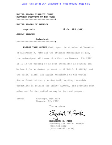
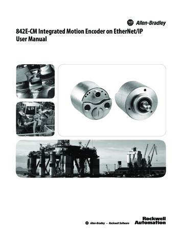
Chapter2About the EncoderNetXS (Axis)ModLink 2Link 1Screw coverThe 842E-CM Integrated Motion encoder on EtherNet/IP provides afeedback-only axis for midrange drive applications on EtherNet/IPnetworks.FeaturesEncoder VersionBulletin xxxThe 842E-CM encoder features include: Compatibility with star, linear, and device level ring topologies Robust nickel code disk for harsh ambient conditions Configurable resolution per revolution: 1 to 262,144 High precision and availability Ball bearing spacing of 30 mm for longer life Face mount flange and servo flange/blind hollow shaft andthrough hollow shaft 18-bit single turn resolution 30-bit total resolution multi-turn resolutionRockwell Automation Publication 842E-UM002A-EN-P - November 201315
Chapter 2About the EncoderCIP Sync OverviewEtherNet/IP uses CIP Sync and CIP Motion technologies to provide realtime closed-loop motion control with standard Ethernet. This topologyindependent network provides a simplified integration of the entirecontrol solution on one network.CIP Sync provides a mechanism to synchronize clocks betweencontrollers, I/O devices, and other automation products in yourarchitecture with minimal user intervention. The EtherNet/IP network isthe only network that supports CIP Sync time synchronization.CIP Sync brings together CIP (Common Industrial Protocol) with theIEEE 1588-2008 standard for time synchronization. CIP Sync providesaccurate real-time (Real-World Time) or Coordinated Universal Time (UTC)synchronization of controllers and devices connected over CIP networksand the ControlLogix backplane. This technology supports highlydistributed applications that require time stamping, sequence of eventsrecording, distributed motion control, and increased controlcoordination.CIP Sync provides the capabilities to perform the following functions: Create sequence of events applications System-wide synchronization of time for CIP-based networks Integrated Motion on the EtherNet/IP network applicationsTypical ConfigurationsThis section explains typical configurations and topologies. The 842E-CMencoders can be connected in any of three network topologies: star,linear or device level ring (DLR).IMPORTANT16Rockwell Automation recommends that you use no more than 50 nodes on asingle DLR or linear network. If your application requires more than 50 nodes,we recommend that you segment the nodes into separate, but linked, DLR orlinear networks.Rockwell Automation Publication 842E-UM002A-EN-P - November 2013
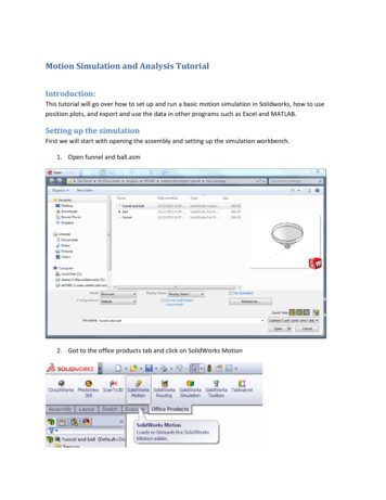
About the EncoderChapter 2Star TopologyCompactLogix controller programming networkCompactLogix 5370 controllerLogix Designerapplication1 (Front)2 (Rear)Kinetix 5500 servo drive system1585J-M8CBJM-xEthernet (shielded) cable1585J-M8CBJM-OM30.3 m (1.0 ft) Ethernet cablefor drive-to-drive connections1783-BMSStratix 5700 switchPanelView Plus display terminal1734-AENTR POINT I/OEtherNet/IP adapter842E-CM encoderThe star structure consists of a number of devices connected to a centralswitch.IMPORTANTWhen this topology is used, make the Ethernet connection on the 842E-CMencoder to the Link 1 connection. The Link 2 Ethernet connection must remainunused.Rockwell Automation Publication 842E-UM002A-EN-P - November 201317
Chapter 2About the EncoderLinear TopologyThe linear topology uses the embedded switching capability to form adaisy-chain style network that has a beginning and an end. Lineartopology simplifies installation and reduces wiring and installation costs,but a break in the network disconnects all devices downstream from thebreak. When this topology is used, both Ethernet connections on theencoder may be used. For the network connection use Link 1, Link 2, orboth.CompactLogix controller programming networkCompactLogix 5370 controllerLogix DesignerapplicationKinetix 5500 Servo Drive System1 (Front)2 (Rear)1581585J-M8CBJM-OM30.3 m (1.0 ft) Ethernet cablefor drive-to-drive connections1585J-M8CBJM-xEthernet (shi elded) cablePanelView Plusdisplay terminal181734-AENTR POINT I/O EtherNet/IP AdapterRockwell Automation Publication 842E-UM002A-EN-P - November 2013842E-CM encoder
About the EncoderChapter 2Device Level Ring TopologyA DLR network is a single-fault-tolerant ring network intended for theinterconnection of automation devices. DLR topology is advantageous asit can tolerate a a break in the network. If a break is detected, the signalsare sent out in both directions. With this topology, use both the Link 1and Link 2 Ethernet connections on the 842E-CM encoder.CompactLogix controller programming networkCompactLogix 5370 controllerLogix Designerapplication1 (Front)2 (Rear)1734-AENTR POINT I/OEtherNet/IP adapterPanelView Plusdisplay terminal1783-ETAPmoduleKinetix 5500 servo drive system1585J-M8CBJM-OM30.3 m (1.0 ft) Ethernet cablefor drive-to-drive connections.842E-CM encoder1585D-M4TBJM-xEthernet (shielded) cableRockwell Automation Publication 842E-UM002A-EN-P - November 201319
Chapter 2About the EncoderNotes:20Rockwell Automation Publication 842E-UM002A-EN-P - November 2013
Chapter3InstallationMechanicalThis chapter describes how to install the 842E-CM integrated motionencoder on EtherNet/IP.Also refer to the installation sheet provided in the box, publication No.842E-IN002 (10000481742).Shaft Rotation DirectionWhen you view the encoder from the shaft side, the shaft rotation isclockwise (CW) or counterclockwise (CCW), as shown.Mounting with a Solid Shaft1. Be sure to select the proper size flexible coupling clamp to mate tothe encoder shaft, e.g., 845–FC–*–*. See encoder accessories in theSensors catalog (C116-CA001).ATTENTION: Do not rigidly connect the encoder shaft to the machine; this willcause premature failure of the encoder or machine bearings. Always use aflexible coupling.Rockwell Automation Publication 842E-UM002A-EN-P - November 201321
Chapter 3Installation2. Use the dimension drawings in the installation instructions todetermine the encoder mounting hole locations (see “RelatedDocumentation” on page 9).3. Slide the flexible coupling onto the shaft, but do not tighten the setscrews.4. Mount the encoder and tighten with three size M4 mountingscrews (not supplied).5. Center the flexible coupling and tighten the set screws.Mounting with a Hollow ShaftIMPORTANTBe sure the mating shaft is chamfered and grease-free.1. Loosen the screw on the clamping ring with a 2.5-mm star driver.2. Slide the encoder onto the mating shaft until the flex mount restson the machine surface.ATTENTION: The encoder should slide freely onto the shaft; if not, do not force.Check the shaft for interferences such as gouges, burrs, rust, or size.3. Hold encoder firmly and mark the two mounting holes. (Ifmounting holes already exist, proceed to Step 6.)4. Slide the encoder off. Drill and tap the marked holes to accept M4(or equivalent) screws.5. Slide the encoder back onto the shaft until the
Components of an Integrated Motion Application Requirements System Component Cat. No. Description Logix Controller Platform 1769-L18ERM 1769-L27ERM 1769-L30ERM 1769-L33ERM 1769-L36ERM CompactLogix 5370 controllers with Integrated Motion on the EtherNet/IP network. Linear, device-level rin