Transcription
SolidWorksMotion StudyTutorialBy:Mohamed Hakeem Mohamed NizarMechanical Engineering Student- May 2015South Dakota School of Mines & TechnologyAugust 2013
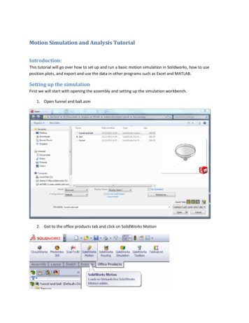
Getting StartedThis tutorial is for you to understand the basics of SolidWorks Motion Analysis and use it tosimulate and get the results for problems.SolidWorks Motion Analysis allows you to study two major types of problems relating to themotion of solid bodies.1. Kinematics: Study of the motion of a rigid body without considering the forces thatresult in the motion of the body.2. Dynamics: Study of the motion of a rigid body as a result of the applied external forceson the body.SolidWorks Motion Analysis allows you toanswer the following questions:1. Will the assembled components of yourdesign move as you intended?2. Will the assembled components of yourdesign collide when it’s in motion?4. What are the magnitudes of the forcesbetween two parts in contact with oneanother?5. What is the path of the solid body?6. What is the velocity, acceleration, angle, orreaction force at an instant?In order to do motion analysis you need toadd motion analysis plugin to your assemblyfile.Tools Add-Ins Select SolidWorks Motion.Note: Most of the details in this page are extracted from ‘SolidWorks Motion,’ 21 July 2011, byProfessor Erik Spjut, Engineering Clinic Director, lidworks motion final.pdfSolidWorks Motion Study by: Mohamed Hakeem Mohamed NizarPage 1
Introduction to Motion AnalysisMotion Analysis can be found only in assembly files. It has several features related to themotion of an assembly file. Figure below shows a screen shot of a simple pin connectionassembly file.Features of Motion Study Motion Study Tab – This tab allows us to analyze the motion study of the assembly file.Motion Manager Tree – This contains all the parts, sub-assemblies, mates, and thesimulation elements.Calculate – This button allows calculating the motions of the assembly and helps toupdate after changes made.Play – This button allows us to play the animation to see how it works after calculatingthe motion.Playback Speed – This helps to reduce or increase the speed of the animation.Save Animation – This button helps to save the animation as a video.SolidWorks Motion Study by: Mohamed Hakeem Mohamed NizarPage 2
Motor – This allows simulating a motor or giving a torque to the animation such as atpin connections.Spring – This allows simulating a spring in motion where you can edit the springconstant and length.Force – This allows simulating forces on any part of an object.Contact – This allows stopping the interference between solid objects and adjusting thefriction between objects when it is in motion.Gravity – This allows simulating the effect of gravity on solid objects.Results & Plots – This allows getting the results and plots for displacement, velocity,force, angles, etc.Zoom Time Scale – This allows zooming in/out the timeline.Key Point – This point decides where the motion has to be stopped.Time line – This shows the moving time frame.Introduction to MatesMates are crucial for motion analysis. There are some typical mates such as coincident,concentric, parallel, tangent, and so on that we use to assemble and put the parts together.This section should be a review of material covered in ME-110.The following screen shots of an assembly file shows some of the typical mates.1. Before mates are applied to the assemblySolidWorks Motion Study by: Mohamed Hakeem Mohamed NizarPage 3
2. Select the cylindrical face of the bar and pin holder and it will mate it to concentric bydefault.3. Select the face of the rod and the inner face of the pin holder (Right click on the surfaceof the pin holder and then click select other to select the inner face) and it will mate it tocoincident by default.SolidWorks Motion Study by: Mohamed Hakeem Mohamed NizarPage 4
4. Select the cylindrical face of the pin and pin holder and it will mate it to concentric bydefault.5. Select the circular face of the pin and the face the pin holder as shown in the figurewhich will select the coincident mate by default.The above example gives a demonstration of basic assembly and mates. You can download thepart and assembly files from the website under class materials. Create a new assembly file andpractice to understand it well.SolidWorks Motion Study by: Mohamed Hakeem Mohamed NizarPage 5
Lesson 1This lesson will help you to get familiar with forces acting on a body. You can download the partand assembly files from the website under class materials. Open the assembly file. Click the mate option in assembly features Select the top surface of the floor and thebottom surface of the cube which will go for the mate coincident by default Click thecheck mark to add another mate.SolidWorks Motion Study by: Mohamed Hakeem Mohamed NizarPage 6
Dealing with friction and matesNote: The typical way to attach an object to the floor or to another object is by adding acoincident mate in between those two faces so they will be touching together at theselected surfaces. This would change if we need to add friction into our motion analysis.When you need to add friction, first replace the coincident mate with a parallel matewithout changing anything else. Then add friction via Solid Body Contact. Click the side edge of the cube and the edge of the floor as shown below It wouldselect the concentric mate by default, but go and select the distance mate as shown andspecify a distance between those two line. This mate causes the box move along astraight path. To change the mass properties go to tools Mass properties. You can change the mass(make it 5 kg) and the location of center of mass.Gravity needs to be added in order to simulate the effect of weight. Choose thedirection of gravity as you want it to be. SolidWorks Motion Study by: Mohamed Hakeem Mohamed NizarPage 7
Add force to the object. You can choose the face where the force is acting and then canchange the direction as shown below. Then you can change the magnitude of the force(make it 10 N).SolidWorks Motion Study by: Mohamed Hakeem Mohamed NizarPage 8
Calculate the motion. Now you can play it and see how it behaves when a force is applied. You can drag thekey point until when it reaches the end of the floor.SolidWorks Motion Study by: Mohamed Hakeem Mohamed NizarPage 9
Advanced Lesson 1 You can get the results in a plot as shown below. Results and Plots Select category Select sub-category Select result component. Then select the face which you want toget the results of. This would give the plot of the result versus time or else you selectnew results and change results instead of time. You can see the plot by expanding theresults in the motion manager tree right click the plot you want to see Show plot.To see the data points in excel, right click on the plot and the click Export CSV. Velocity vs Time plot ( without friction)SolidWorks Motion Study by: Mohamed Hakeem Mohamed NizarPage 10
Acceleration vs Time plot ( without friction ) Add contact to use the friction features. Unselect the material option to edit the staticand kinetic friction coefficients. If you want to choose the materials SolidWorks will setthe friction values to match the materials. When working with friction, coincident mateshould be either suppress or deleted from the motion analysis. Do not specify masswhen working with friction. You can change the mass by creating a materian changingthe density of it as shown in “Tips and Tricks” section.SolidWorks Motion Study by: Mohamed Hakeem Mohamed NizarPage 11
Note: Please make sure to move the time bar in the timeline to initial (ie. 0 seconds)before you make any changes to your force, torque, or mates!ExerciseDo all this calculations and plots over 0 to 0.65 seconds.1. Do the same problem with mass 10 kg and force 15 N without adding any friction(uncheck the friction option) and plot velocity and acceleration vs time.2. Do the same problem with mass 10 lbm and force 4 lbf without adding any frictionand plot velocity and acceleration vs time.3. Do the same problem with mass 4 kg and force 20 N with 𝜇𝑘 0.25 and 𝜇𝑠 0.3 andplot velocity and acceleration vs time. (Note: When dealing with friction, please checkthe highlighted note in lesson 1)SolidWorks Motion Study by: Mohamed Hakeem Mohamed NizarPage 12
Lesson 2This lesson will help you to get familiar with simulation of a spring. You can download the partand assembly files from the website under class materials. Open the assembly file Do the similar mates as in the lesson 1 Click the motion analysis option as shown.SolidWorks Motion Study by: Mohamed Hakeem Mohamed NizarPage 13
Add a spring to it by selecting the face of the box and the face of base as shown. Thenyou can change the spring stiffness and unstretched length of it as shown. You can change the display of the spring such as diameter, thickness, and number ofcycles. This part will not affect any mechanical properties of the spring. Now you can change the initial length of the spring by adding a mate to it. As shownhere, add a distance mate in between the two faces. Here I enter the initial lengthlonger than the unstretched length to give an oscillation. Make sure to suppress (Rightclick on the mate and then select suppress) or delete the mate from the motion studybefore you calculate motion or else the box will not move.SolidWorks Motion Study by: Mohamed Hakeem Mohamed NizarPage 14
Assign mass (10kg) and Calculate motion.In addition you can add friction as shown in lesson 1 and then plot the results of desiredparameters, but you need to consider the fact that you can’t assign mass and you haveto create a new material as shown in “Tips and Tricks” section.Velocity vs Time plotSolidWorks Motion Study by: Mohamed Hakeem Mohamed NizarPage 15
Acceleration vs Time plotNote: The spring won’t be on display unless you click the spring on the motion manager treewhile it is playing.Exercise1. Do the same problem with mass 5 kg and plot velocity and acceleration vs time.2. Do the same problem (mass 10 kg) with spring constant 200 N/m.3. Do the same problem (mass 10 kg) with initial length 0.4m keeping the unstretchedlength the same.4. Do the same problem while setting the unstretched and initial lengths equal to 0.5mand applying a 5 N force in the positive x direction.SolidWorks Motion Study by: Mohamed Hakeem Mohamed NizarPage 16
Lesson 3This lesson will allow you to get familiar with motors. You can download the part and assemblyfiles from the website under class materials. The first few mates are exactly the same as shown in “Introduction to Mates” at thebeginning. The images show the completed assembly. After assembling the pin holder with the two bars, insert component Insert Slide partfile. Then in mates, click the faces as shown which would select the coincident mate bydefault.SolidWorks Motion Study by: Mohamed Hakeem Mohamed NizarPage 17
Click the faces as shown which would select the coincident mate by default, but changeit to parallel mate as shown.SolidWorks Motion Study by: Mohamed Hakeem Mohamed NizarPage 18
Insert the component sliding box. Then click the cylindrical faces as shown which wouldselect the concentric mate by default. Select the faces as shown which would select the coincident mate by default.SolidWorks Motion Study by: Mohamed Hakeem Mohamed NizarPage 19
Now select the circular face of the pin on the sliding bar and the front face of the bar as shownwhich would select the coincident mate by default. Right click anywhere on the part Slide and select fix to make that part fixed.SolidWorks Motion Study by: Mohamed Hakeem Mohamed NizarPage 20
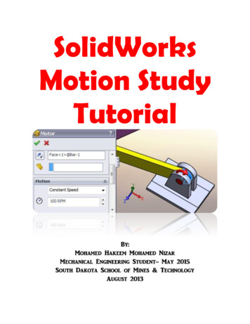
Now select the top face of the sliding box and the pin holder as shown. Then select the distancemate and enter the values as shown to make it start at a lower position. Click motor in the motion tab to give the rod an angular velocity. Select the curved face of therod as shown and give a constant angular velocity of 100 RPM. Assign 5 kg mass for the block and then go to the motion analysis tab and click calculate.SolidWorks Motion Study by: Mohamed Hakeem Mohamed NizarPage 21
Angular Velocity vs Time plot. Angular Acceleration vs Time plot.SolidWorks Motion Study by: Mohamed Hakeem Mohamed NizarPage 22
Displacement of the Sliding Box vs Angle of the rod plot.Exercise1. Do the same problem with a 10kg mass box and show all three plots.2. Do the same problem with the same mass but 150 RPM constant speed and show all three plots.3. Do the same problem with 5 rad/s constant angular velocity and show all three plots.SolidWorks Motion Study by: Mohamed Hakeem Mohamed NizarPage 23
Lesson 4This lesson will allow you to get familiar with a simple impact situation. You can download thepart and assembly files from the website under class materials. Make the assembly file and make sure the ball is above where the floor is by selecting thedifferent views to make sure of its position. Then create a distance mate between the ball andthe floor as shown (1m) in the model tab. Add solid body contact between the ball and the floor. Check the restitution coefficient (0.5)option.SolidWorks Motion Study by: Mohamed Hakeem Mohamed NizarPage 24
The default simulation setting sare often not accurate enough to capture impact events. Thereare two ways you can change the defaults. You can use either check the “Use Precise Contact”option or increase the frames per second. The preferred solution is Use Precise Contact. Calculate the motion and plot the results of the displacement of the ball vs time.SolidWorks Motion Study by: Mohamed Hakeem Mohamed NizarPage 25
Linear velocity vs Time plot Linear Displacement vs Linear Velocity PlotSolidWorks Motion Study by: Mohamed Hakeem Mohamed NizarPage 26
Exercise1. Do t
SolidWorks Motion Study by: Mohamed Hakeem Mohamed Nizar Page 1 Getting Started This tutorial is for you to understand the basics of SolidWorks Motion Analysis and use it to simulate and get the results for problems. SolidWorks Motion Analysis allows you to study two major types of problems relating to the motion of solid bodies. 1. Kinematics: Study of the motion of a rigid body without considering the