Transcription
G-code manualDrufelCNC, 2020
ContentAnnotation . 4G00 - Accelerated movement. 5G01 - Linear interpolation . 5G02 - Circular interpolation . 9G03 - Circular interpolation . 9G04 - Pause . 15G10 - Enable data entry mode. 15G17 - XY plane selection . 17G18 - XZ plane selection . 17G19 -YZ plane selection . 17G20 - Input inch data. 21G21 - Enter metric data . 21G31 - Movement of axes to a given position . 21G38.n - Straight probe . 23G50 - Scale mode . 23G51 - Scale mode . 23G53 - Disabling the offset of the origin of the coordinate system . 25G68 - Rotate coordinate system . 25G69 - Cancel Rotation . 26G80 - Cancel Canned Cycle . 27G81 - Simple Drilling Cycle . 27G82 - Drilling Cycle with Dwell . 28DrufelCNC - software for controlling CNC machines. Read more: https://drufelcnc.com2
G90 - Absolute positioning mode. . 29G90.1 - Absolute distance mode for I , J and K offsets. . 29G91 - Relative positioning mode. . 30G91.1 - Incremental distance mode for I, J and K offsets. 30G98 - Canned Cycle Return or Feed Rate Modes . 31G99 - Canned Cycle Return or Feed Rate Modes . 31DrufelCNC - software for controlling CNC machines. Read more: https://drufelcnc.com3
AnnotationThis document is a G code user guide. These G-codes can be used in the DrufelCNCsoftware. G-code is a programming language for numerically controlled machinesand machine tools.DrufelCNC - software for controlling CNC machines. Read more: https://drufelcnc.com4
G00 - Accelerated movement.Code G00 is used for faster movement. Accelerated movement is necessary for quickmovement.The speed of the tool is too high and inconsistent!The use of the G00 code reduces the overall processing time.G01 - Linear interpolationCode G01 is designed to perform tool movement in a straight line at a given speed.The main difference between the G01 code and the G00 is that with linearinterpolation, the tool moves at a given speed. Movement speed is indicated by the Fcommand. Conventionally, a frame for linear interpolation is written as follows:G01 Xn.n Yn.n Zn.n F n.nG01 Xn.n Yn.n Zn.n An.n Bn.n Cn.n Fn.nConsider the following simple program:X0Y0 - zero positionG00X0Y0Z-5 - lowering the cutter along the z axis by -5mmG01X30Y50F50 - moving the tool to a point (30; 50) with a working feed speed of 50mm / minG00X30Y50Z10 - raising the cutter along the z axis by 10mmDrufelCNC - software for controlling CNC machines. Read more: https://drufelcnc.com5
Let's complicate the program a bit. Let's write a program cutting a polygon.G00Z10 ;raise the cutter to a safe position from the workpieceG00X0Y0 ;zero positionG01X0Y0Z-5F50 ;lowering the cutter along the axis on z by -5 with a working feedspeed of 50 mm / minG01X30Y50F50 ; moving the tool to a point (30; 50) with a working feed speed of 50mm / minG01X30Y100 ;moving the tool to a point (30; 100)G01X0Y150 ;moving the tool to a point (0; 150)G00X0Y150Z10 ;raising the cutter along the axis by z by 10G00X0Y0 ;move to zero positionThe speed value can be set once. You can also shorten your code. Short code willlook like this:G00Z10G00X0Y0G01Z-5F50DrufelCNC - software for controlling CNC machines. Read more: https://drufelcnc.com6
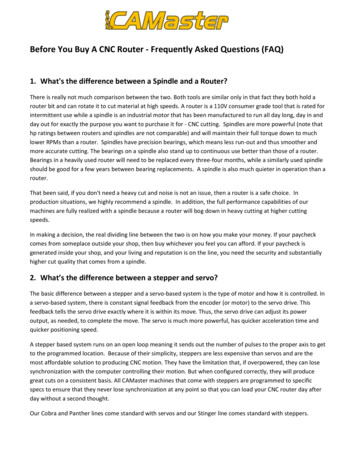
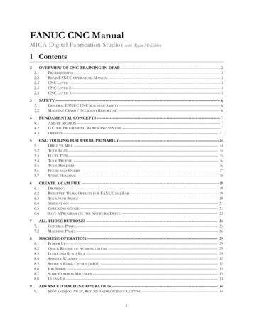
G01X30Y50G01Y100G01X0Y150G00Z10G00X0Y0Let's try to write a program for a more complex figure:G00F300 ;for G00 commands we set the speed to 300G01F300 ;for G01 commands we set the speed to 300M03S24000 ;turn on the spindle at a speed of 24000 rpmG00Z3 ;raise the cutter to a safe positionG00X25.325Y47.45 ;moving the tool to a point (25.325; 47.45)Z-0.03 ;axis milling cutter axis z -0.03X31.275Y29.275 ;move tool to pointX50.675Y29.325 ;moving the tool to a pointX34.95Y18.125 ;move the tool to a pointX41Y0 ;move tool to pointX25.325Y11.25 ;move tool to pointX9.625Y0 ;move tool to pointX15.675Y18.125 ;move tool to pointX-0.05Y29.325 ;move the tool to a pointX19.35Y29.275 ;moving the tool to a pointX25.325Y47.45 ;move the tool to a pointG00Z3 ;raising the cutter along the axis by z by 3M05 ;spindle shutdownG00X0Y0 ;move to zero positionDrufelCNC - software for controlling CNC machines. Read more: https://drufelcnc.com7
DrufelCNC - software for controlling CNC machines. Read more: https://drufelcnc.com8
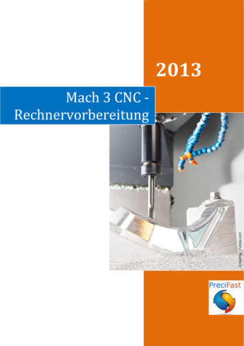
G02, G03 - Circular interpolationCodes G02 and G03 are designed to perform circular interpolation. G02 command isused to move in an arc clockwise, and G03 - counterclockwise.The direction of movement is determined when we look at the tool from the spindleside, in the negative direction of the Z axis. As with linear interpolation, in thecircular interpolation block, you must specify the feedrate F.There are two ways to form a circular interpolation frame: setting the center of the circle using I, J, K; setting the radius of the circle with R.Arc with I, J, KFor a complete description of the arc, it is not enough to specify only the coordinatesof its end point. You must also specify the coordinates of the center.I, J, K are used to determine the center of the arcUsing I, J, and K, you specify the relative (incremental) distances from the startingpoint of the arc to its center.DrufelCNC - software for controlling CNC machines. Read more: https://drufelcnc.com9
You must specify a positive value for I and a negative value for JYou must specify a positive value for I and a positive value for JArc with RA simpler way to specify the center of the arc is based on applying the address R(radius). To unambiguously determine the shape of the arc, you must specify thecorresponding sign in front of the numerical value of the radius R. For an arc that isgreater than 180 , the value of R will be negative. For an arc that is less than 180 ,the R value will be positive.DrufelCNC - software for controlling CNC machines. Read more: https://drufelcnc.com10
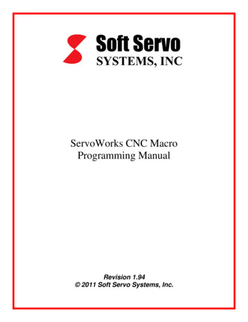
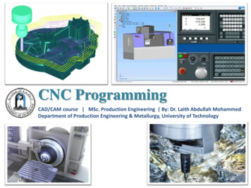
Since the arc is less than 180 (its center is located outside the chord), then R willhave a positive valueSince the arc is greater than 180 (its center is located inside the chord), then R willhave a negative valueUsing G02 and G03Let's see how circular interpolation works, using an example. The following fragmentof the control program moves the tool along an arc with a radius of 8 mm from pointA (0; 0) to point B (8; 8) with a working feed speed of 80 mm / min.G01X0Y0G02 X8.0 Y8.0 I8.0 J0.0 F80Since the center of the arc is at a distance of 8 mm along the X axis and 0 mm alongthe Y axis relative to the starting point A, then I will be 8.0, and J is 0. The resultingarc is only a quarter of the full circle. Let's try to describe the whole circle gradually.DrufelCNC - software for controlling CNC machines. Read more: https://drufelcnc.com11
Moving along an arc with R 8 from point A (0; 0) to point B (8; 8)The next frame moves the tool from point B (B1) to point B2. Since the feedrate doesnot change, there is no need to re-specify the data F-word.Since the center of the arc is at a distance of 0 mm along the X axis and 8 mm alongthe Y axis relative to point B, then I will be 0, and J will be -8. Thus, we were able tocreate a displacement along an arc from point A to point B2 using two frames.Currently, most CNC systems allow you to perform an operation to describe the fullcircle in two or even one frame. Therefore, the movement from point A to point Ccan be written as follows:G01X0Y0G02 X8.0 Y8.0 I8.0 J0.0 F80G02 X16.0 Y0.0 I-8.0 J0.0Modern CNC systems allow the description of such an arc in one blockG01X-8Y0G02 X-8.0 Y0.0 I8.0 J0.0Full circle description in one frame is also possible.DrufelCNC - software for controlling CNC machines. Read more: https://drufelcnc.com12
Spiral.If the XY plane (G17) is activated and the Z word is programmed in the circularinterpolation block, then a spiral forms in the XY plane. The direction of the arc orspiral in the XY plane can be determined visually.An example of a 38J38G02Z-70I38J38G02Z-80I38J38G01X10Y10DrufelCNC - software for controlling CNC machines. Read more: https://drufelcnc.com13
An example of a finished program:G00X0Y0 ;zero positionM3 S6000 ;turn on the spindle at a speed of 6000 rpmG00Z5 ;raise the cutter to a safe positionG01X14.1421Y-14.1421 ;moving a tool to a pointG01Z-0.5F700 ;moving a tool to a point at a speed of 700G02X14.1421Y14.1421R-20 ;using the G02 command using RG01X40.0Y-14.1421 ;moving a tool to a pointG03X40.0Y14.1421R-20 ;using the G02 command using RG01x14.1421y-14.1421 ;move the tool to a pointG00Z5 ;raising the cutter along the axis by z by 3M5 ;spindle shutdownG00X0Y0 ;move to zero positionDrufelCNC - software for controlling CNC machines. Read more: https://drufelcnc.com14
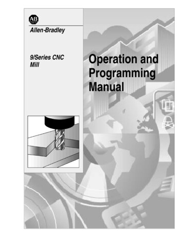
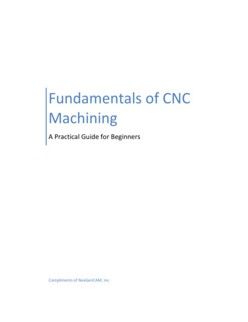
G04 - PauseCommand G04 is used to delay control program execution or pause. This modelesscode is used in conjunction with the S- or P-address, which indicates the length ofthe exposure time. Usually this time is from 0.001 to 99999.999 seconds.Code G04, S- or P-address are programmed together in a single block that does notcontain any movements.If P is used to determine the holding time, then the decimal point cannot beprogrammed. Address P determines the holding time in milliseconds, and S inseconds.Example:G04 S1.5 ;shutter speed 1.5 seconds;G04 P200 ;shutter speed 200 milliseconds.G10 - Enable data entry mode.Set new coordinates for the originFormat: G10 X10 Y10 Z10 A B CThe preparatory function G10 is modal and remains active until it is canceled by codeG11, G53.Let's look at an example:G00X0Y0M3 45Y45M5G00X0Y0DrufelCNC - software for controlling CNC machines. Read more: https://drufelcnc.com15
Add a line: G10 X10 Y30DrufelCNC - software for controlling CNC machines. Read more: https://drufelcnc.com16
G17, G18, G19 - Plane selectionIn CNC programming, there are 3 G-codes for selecting a plane during NCprogramming, which are used to define two axes: X, Y or Z. The plane selection ismodal and is valid for everyone until you enter a different circular plane command.The 3 Plane selection G-Codes are:G17 for XY PlaneG18 for XZ PlaneG19 for YZ PlaneXY plane selection with G17 code.The XY G17 plane selection code is set by default and sets the plane to the circularinterpolation mode G02 and G03.In the circular interpolation blocks, the words X, Y, Z, I and J. are valid. The word K isnot valid. If the Z word is programmed in a circular interpolation block, then a spiralforms in the XY plane. The direction of the arc or spiral in the XY plane can bedetermined visually: Positive direction X - to the right side, positive direction Y - up.The XY plane has a right-handed coordinate system. In G17, the endpoint of the arc isdefined in the block by the words X and Y. The center point of the arc is defined inthe block by the words I and J.G17 is activated by default. Code G17 is canceled by codes G18 and G19.Example:G17G00X0Y0M3 S6000G00Z5G01X14.1421Y-14.1421DrufelCNC - software for controlling CNC machines. Read more: https://drufelcnc.com17
00X0Y0XZ plane selection. Code G18XZ plane selection code G18 sets the plane to circular interpolation mode G02 andG03. In the circular interpolation blocks, the words X, Y, Z, I and J. are valid. The wordJ is not valid. If the word Y is programmed in a circular interpolation block, a spiralforms in the XZ plane. The direction of the arc or spiral in the XZ plane can bedetermined visually: The positive X direction is to the right, the positive Z direction isup. The XZ plane has a right-handed coordinate system.Code G18 is canceled by codes G17 and G19.Example:G18G00X0Z0M3 S6000G00z
DrufelCNC - software for controlling CNC machines. Read more: https://drufelcnc.com 17 G17, G18, G19 - Plane selection In CNC programming, there are 3 G-codes for selecting a plane during NC programming, which are used to define two axes: X, Y or Z. The plane selection is