Transcription
WELCOME TOMECH 211, MechanicalEngineering DrawingTime: M W 10:15 - 11:30Credits: 3.5 Session: Fall 2013IntroductionLecture 1
Whatever area you willchoose This course is fundamental.
A bit of history The objective need to communicate
A bit of history The time line
History in images
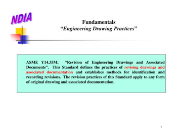
Artistic Drawing“Paper could take aboutanything”Observe the waythe posts are crossingHave you ever seensuch a construction?
The fundamental difference ?Artistic DrawingMechanical/Technical drawing
Content of the CourseIntroduction to graphic language and design — means andtechniques. The third and the first angle projections.Orthographic projection of points, lines, planes and solids.Principal and auxiliary views. Views in a given direction.Sectional views. Intersection of lines, planes and solids.Development of surfaces. Drafting practices. Dimensioning,fits and tolerancing. Computer-aided drawing and solidmodelling. Working drawings — detail and assemblydrawing. Design practice. Machine elements representation.Case Study
Content of the CourseA, B, C, D ARE POINTSADBC
Content of the CourseA, B, C, D ARE POINTSAB, BC, CD, DA, CA ARE LINESADBC
Content of the CourseA, B, C, D ARE POINTSAB, BC, CD, DA, CA ARE LINESAABC, CDA ARE PLANESDBC
Content of the CourseA, B, C, D ARE POINTSAB, BC, CD, DA, CA ARE LINESAABC, CDA ARE PLANESABCD IS A SOLIDDBC
Content of the CourseA, B, C, D ARE POINTSAB, BC, CD, DA, CA ARE LINESAABC, CDA ARE PLANESCASESTUDYBEXPLAINWITH TEXTLAICNHCTEACOMMUNICATIONRTISTICISOMETRICPPR ARO ALJE LEC LTIONPERSPECTIVEDM EVEN ELT OPINTERSECTIONABCD IS A SOLIDGRAPHICSCD
Mission of the Course Enables the students to learn the techniques andstandard practices of technical graphics At the end of the lectures, one would be able to:– Read a working or assembly drawing (blueprint)– Represent mechanical components in multiview orthographicrepresentation– Create conceptual design sketches– Create assembly drawings (limited)– Capability to use AutoCAD for 2-D representations* The amount of acquired skills will be proportional to the capabilities, will and effort of the individuals
Main Objective of the Course To acquire essential skills that are part of the mechanicalengineering practice To be able to communicate with other mechanicalengineering professionals regardless their spokenlanguage To be able to communicate with manufacturers ofmechanical systems
Class Logistics 3 teaching hours/week M-W-- 10:15 –11:30 12 weeks and one Review week 2 hour of tutorial – following the class 4 hours of laboratory – every 4 Weeks 3 parallel sections
Class Materialshttp://users.encs.concordia.ca/ nrskumarRequired textbookRecommended textbook
Class Materials Tutorial materials – handed in during tutorial periods, also availableon the web. Tutorials will be held in AUTOCAD labs and set ofpracticing drawings available on the web site to learn AUTOCAD Assignments: 8 – available on the internet Solutions to the assignments will be with PODs after assignmentdue date RECOMMENDATION: Attend the classes!
Class MaterialsLect Textbook Description#Chapter11, 6Introduction to graphic language and design, means and techniques, views of ageometric object, multiview projections, applications and examples - , 2 2, 3, 4Instruments, geometric constructions, CAD tools, demonstration examples - , 35, 7, 8, 10 Sketching and shape description, shape generation, sectional and auxiliary views,examples and applications - , 419Descriptive Geometry– Points and lines, examples - 519Descriptive Geometry – Points and lines, examples - , 620Descriptive Geometry – Parallelism & perpendicularity – examples - , 721Descriptive Geometry – Solids in space and Intersections – examples - , 8* 21, 22Descriptive Geometry – Intersections, examples, , 9 22Descriptive Geometry – Developments, examples, - , 10 11, 12Dimensioning and tolerancing, examples and applications - , 11 13Threads, fasteners, springs, gears, examples - , 12 14Design and working drawings – examples, Design case study - , 13 ---Makeup class, Review– , * During the tutorial period of week # 8, the midterm test will be carried - PowerPoint presentation, - Material available on course website, Lecture to be done on board/screen
Class Instructor and ContactsInstructor: Dr. S. NarayanswamyOffice: EV BuildingRoom: 004 –124Phone: 848-2424 (7923)Office Hours: J 10:00 –12:00 or by appointmente-mail: nrskumar@encs.concordia.caCourse Web Site: http://users.encs.concordia.ca/ nrskumar/
What you have to do Attend the lectures, laboratories and tutorials – try to understand theobjectives as well as the procedures Use time at home to read and study the chapters in the book – usethe material posted on the internet Do your home-work by yourself – consult only your colleagues, tutor,lab instructor or class instructor Submit on time your assignments Write the midterm test – this is a good measurement means for yourperformance in the class Write the final exam with confidence that you will do very well
Midterm Exams Scheduled for October 28th, 2013 and it will beconducted during the tutorial period. The midterm test is not mandatory but isrecommended If the midterm result is better than the final, it willbe counted for 10% towards final grade.
Laboratory There is lab component to this course You will be learning about few machineries There are four of them done in H-1067once 4 weeks (4 hours a week). Safety is important and the details areavailable in the course outline.
Grading Scheme To pass, it is imperative to work during the term. The following grading scheme will be used for those whowrote the midterm and their grade is higher than thegrade in the final:– Assignments: 16%– Midterm Examination: 10%– Laboratory 14%– Final Examination 60% who do not write the midterm or theirmidterm grade in below the final:– Assignments: 16%– Laboratory 14%– Final Examination 70%
Content of the first lecture Graphics as communication means A bit of history Multiview representation and orthographicprojections Technical procedures How to generate multi-view orthographicprojection Representation rules
Mechanical components
Geometryis a fundamental thing!In NatureIn Human Need http://www.webshots.com/g/55.html
Introductionto Graphic Language and Design Why graphics is necessary?– Communicate information that would not be possible to exchangein writing Why not use pictures to communicate visual information?– Usually, a drawing represents something that exists just atconceptual level Why not use pictorial representation?– The information contained in a drawing must be used to build anaccurate component/system.
What is Drawing? Drawing is a graphic representation of a realthing, an idea, or a proposed design Why graphic representation? Graphic method of representation is a basicnatural form of communication of ideas that isuniversal and timeless. It is impossible to explain things through text.
Graphic LanguageA simple component! How hard todefine in words? Try to describe in words thefollowing representation: AMECHANISM
Graphic Language Graphics language is universal
Graphic Language The information can be conveyed regardless thespoken language1.Ÿog¿ 4. * #! y²î‰※7. Ð }z C êÑÒ¶³²²10. @ # &¼2.ÐŷƁţāŖĉ5. Z ¶ æÊ¿ ŠŠŠ8. š ?%ëŢŪųĺ З—11. ※—‘ 3. @µ¶œƒ/6. ¶ ¹ì wd]Ê !;89. ßu *” éÐÐ
Graphic Language When spoken language is known, the information is moreaccurate
Essentials of a good drawing Should represent the concept/idea/geometryclearly Should be able to communicate with others without doubt Should respect the manufacturing feasibility Should favor a lot standardizationLet’s see how to make a good mechanical drawing!
Views An object could be represented in more ways:
Projections/ Drawing Basics The way one is visualizing an object(Simple and sufficient) Two basic projection types – use parallelprojectionPerspectiveParallel
Projections and views (brief)
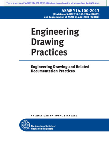
What is perspective representation Representation of objects based on the rule of distance: 2identical object are seen different from different distances– shape is deformed too This type of representation is not used for technicalpurposes in Mechanical Engineering
What should be drawn? What is seen – follow certain rules
Views - Multi-view representationProject the visible and hiddenedges/corners
Views - Multi-view representation
Multi-views A part is represented in multiple views (a single part isseen as more than one part) The representation makes the user to fully understandthe shape of the part, to perceive the relative proportionsof the geometric features and to position the features onewith respect to another The parallel projection principle and the alignment of thefeatures is used in the representation
Type of Projections
Projection planes The component is aligned withrespect to the principal projectionplanes– Top (T) or Horizontal (H)– Front (F) or Vertical (V)– Side (S) or Profile (P) The projection is carried such thateach feature parallel to theprojection planes to be seen as truelength
Object orientation
Projection principles
Projection principles
Projection TypesThird angle projectionFirst angle projection
Relative position of the views All views must be aligned with respect toeach other – feature to feature
Drafting strategies (3 view)
Technical procedures When representing the third view, scale, divider ofmiter line is used to ensure the alignment of thethree views
Example Represent the shown component using multipleview representation
Example Start with the front view The edge C cannot be seen but isrepresented by a dashed line (hiddenfeature)C
Example Align the top view with respect to thefront viewC
Example Complete the representation Later, dimensioning and comments willbe added to the drawing
The principal projection planes The object shouldbe aligned withrespect to theprojection planes
The principal projection planes- unfolded Notice the relationshipbetween the features The depth – distancefrom the front to theobject is measured inthe Horizontal andProfile
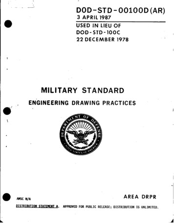
Multi-view Projection DrawingHow to generate Assume the given part asshown besides. Position the part in aconvenient way, to simplifythe representation as muchas possible
Multi-view Projection DrawingHow to generate Select the position of theprojection planes Start with one of theprojections – usually the frontview Each edge is representedbased on the principle of theparallel projection
Multi-view Projection DrawingHow to generate Complete the first view. Use the basic representationPrinciples: visible edge is seen as a fullline non-visible feature isrepresented by a dash-line axes of symmetric featuresare represented by dash-dotlines
Multi-view Projection DrawingHow to generate Continue with the second view Make sure that you haveaccurately align the two views. Use the same rules forrepresentation. The alignment lines must beperpendicular to the edge ofthe projection planes (The lines of sight are alwaysperpendicular to the fold line).
Multi-view Projection DrawingHow to generate Continue with the third view Make sure that you haveaccurately align all views. Use the same rules forrepresentation. The alignment lines must beperpendicular to the edges ofthe projection planes (The lines of sight are alwaysperpendicular to thecorresponding fold lines).
Multi-view Projection DrawingHow to generate Complete the representation Separate the top from theprofile view along the edge(fold line) Unfold the three views to laythem on the same plane
Multi-view Projection DrawingHow to generate This is the 3-vieworthographic representationof the selected part(FLANGE) * Do not erase any of thelines when writing a test
Orthographic multi-view The above part will be projected on all 6projection planes
Orthographic multi-view
Orthographic multi-view
Orthographic multi-view
Orthographic multi-view
Orthographic multi-viewSolid models
Minimum number of views Certain shapes could be described in less number ofviews One must use the minimum number of views forrepresentation
Minimum number of views Do not produce more views than necessary
Centerline Axi-symmetric features are indicated with adash-point line - CENTERLINE
Hints on understanding shapes Try to “see” the way a solid is created outof primitives
Hints on understanding shapes Complex shapes could be generated using Booleanoperations
Pay attention to edges
Projections and views (brief)
Where drawing is used? It is important to know the rationale ofdrawing Drawing is an international communicationlanguage Fast way to convey certain type ofinformation Limited number of concepts are betterrepresented by drawing, but not all
The design process Drawings are created to represent partsthat do not exist yet The designed parts are intended to bemanufactured The drawings must carry all the necessaryinformation that enables the fabrication ofthe part
The design process Design involves constrained creation Constraints: Technology limitsHuman and environment concernsDurability and reliabilityCostMarket requirementsEtc.
The design process REPRESENTATIONPERCEPTIONBasic requirements to be able toKNOWLEDGEperform a designINTUITIONAll the above interacts in yourjudgment even if you are notCONCEPTaware of itPURE CONCEPTYou have to train your judgmentEMPIRICAL CONCEPTto be able to perform solutionNOTIONsolving based thinking IDEAThe graphic helps you to do so
The design process A design is created after analysis, fullunderstanding of requirements andconstraints and synthesis Two individuals may not come with thesame solution to the same problem Example: Connect two straight pipes ND 4” to avoidleaking of the gas and to permit easy maintenanceof the segment
Solutions to the problem Multiple: flanges, clips, clamps, seals, etc.
1. Problem Defn.2. Concept andideasThe design process3. Solutions4. Models/Prototype5. Production andworking drawingsConcurrent engineeringapproach
The design process
The design process
Drawings in emblyDrawingsAssembly
Drawings in productdevelopment
A Component !
Lecture 1 Introduction Time: M _ W _ _ 10:15 - 11:30 Credits: 3.5 Session: Fall 2013 MECH 211, M