Transcription
INTERMEDIATEVOCATIONAL COURSESECOND YEARCIVIL ENGINEERINGDRAWINGFOR THE COURSE OFWATER SUPPLY ANDSANITARY ENGINEERINGSTATE INSTITUTE OF VOCATIONAL EDUCATIONDIRECTOR OF INTERMEDIATE EDUCATIONGOVT. OF ANDHRA PRADESH2005
Intermediate Vocational Course, 2nd Year : CIVILENGINEERING DRAWING (For the Course of WaterSupply and Sanitary Engineering)Author : Sri P. Venkateswara Rao, State Institute of Vocational EducationAndhra Pradesh, Hyderabad.Printed and Published bythe Telugu Akademi, Hyderabad on behalf ofState Institute of Vocational EducationGovt. of Andhra Pradesh, Hyderabad.First Edition : 2005Copies :All rights whatsoever in this book are strictly reserved and noportion of it may be reproduced any process for any purposewithout the written permission of the copyright owners.Price Rs:/-Text Printed at Andhra Pradesh.
AUTHOR & EDITORPuli Venkateshwara Rao, M.E. (STRUCT. ENGG.)Junior Lecturer in Vocational, WS & SEGovt. Junior College, Malkajgiri,Secunderabad.
IVCWATER SUPPLY AND SANITARY ENGINEERINGSECOND YEARCIVIL ENGINEERINGDRAWINGSTATE INSTITUTE OF VOCATIONAL EDUCATIONDIRECTOR OF INTERMEDIATE EDUCATIONGOVT. OF ANDHRAPRADESH
CONTENTSChapterNo.Name of the chapter1.Conventional Signs, Doors,Windows, FootingsBuilding DrawingDetailed Drawings of WaterSupply and DrainageConnections to BuildingLayout of Various WaterSupply and Sanitary Fittingsin Bath and W.COverhead TankSeptic Tank, Manhole andDispersion TrenchLayout Sketch of WaterPurification PlantLayout Sketch of SewageTreatment PlantTracing and Preparation ofAmmonia Prints2.3.4.5.6.7.8.9.No. ofperiods25601121528100533371540054805512054TOTAL PERIODS 160EXERCISEPg. No.
LIST OF PRACTICALSPRACTICALNO.12NAME OF THE PRACTICALPAGENO.3456ENGG. MATERIALS SYMBOLSWATER SUPPLY AND SANITARY FIXTURESSYMBOLSELECTRICAL INSTALLATIONS SYMBOLSFULLY PANELLED DOORFULLY PANELLED WINDOWISOLATED R.C.C. SQUARE FOOTING5910107CROSS SECTION OF LOAD BEARING WALL11891011121314SINGLE ROOM BUILDINGTWO ROOM BUILDINGRESIDENTIAL BUILDING - ISINGLE BEDROOM HOUSERESIDENTIAL BUILDING - IITWO STOREYED BUILDINGLAYOUT AND SECTION OF WATER SUPPLYAND DRAINAGE CONNECTIONS TO A BUILDING16192123252615LAYOUT OF WATER SUPPLY IN SINGLESTOREY BUILDING1616LAYOUT OF DRAINAGE SYSTEM IN MULTISTOREYED BUILDINGOVERHEAD TANK3917SEPTIC TANK FOR 10 USERS4318SEPTIC TANK FOR 50 USERS4319DISPERSION TRENCH452021DROP MANHOLETYPICAL LAYOUT OF WATER TREATMENTWORKSLAYOUT OF SEWAGE TREATMENT PLANT4722343234365053
Civil Engineering DrawingCHAPTER 1CONVENTIONAL SIGNS, DOORS, WINDOWS, FOOTINGSINTRODUCTION :Drawing is the language of engineers. An engineer must be wellconversant with drawings. Drawings represent reduced shape ofstructure and the owner will be able to see what is going to happen.Drawings are prepared as per the requirements of owner. In case ofpublic buildings, the functional aspects are studied and accordingly thedrawings are prepared as per recommendations laid down in NationalBuilding Code (N.B.C) or as per Indian Standard specifications. Anymodifications like additions or omissions can be suggested from a studyof the drawings before actual construction of the structure is started.Drawings provide a language with specific data to Architects, Engineersand workmen at the site to construct the structure accordingly.In case of public buildings or any other civil engineering works, itis essential to work out different items of construction with theirquantities for estimating the total cost of construction project. For thispurpose, drawings of different parts and different views are essential sothat the approval of work from the sanctioning authority can be obtained.Further, the detailed drawings form an essential contract documents,when the work is handed over to a contractor. Hence it is necessary toprepare detailed drawings, which will inform the contractor, the exactinformation, which he needs during the construction of different items ofwork. Drawings, thus prepared should be carefully even after thecompletion of work. Thus, it becomes asses the possibility of furthervertical expansion by referring to the foundation details initially provided.REQUIREMENTS OF GOOD DRAWING:1. Drawing should be clear, simple and clean2. Should agree with the actual measurements by the accurately drawnscaled measurements.-1-
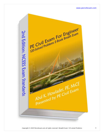
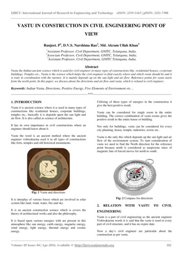
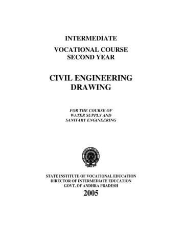
Civil Engineering Drawing3. Exact information should be provided in order to carry out the work atsite without scaling for missing measurements.4. Only minimum notes to support the drawings should be indicated in thedrawings.5. Sufficient space should be provided between the views so as to markthe dimensions without crowding.1.0CONVENTIONAL SIGNS AND SYMBOLS:Conventional signs are used to represent the particular item likestone masonary, brick masonary, concrete etc in the section of drawing.(i.e.,) when the materials are cut by any imaginary plane. Conventionalsymbols are provided to indicate doors, windows, their fixing, movementof shutters. When they are cloud or opened, various water supply andsanitary fixtures like tap, wash basin, W.C., urinals, Kitchen sink, showeretc, symbols are used to indicate the position of electrical fittings likelamp, switch, power socket, fan etc. To indicate positions of furniture ondrawing room, bedroom, suitable symbols are used.The Bureau of Indian standards (B.I.S) has recommended theconventional signs and symbols for the following purposes.1. Avoid confusion and to understand the drawings2. Save the time in making out various details in the drawing3. Identify the various details of materials, Electrical fixtures, watersupply and sanitary fittings, Position of furniture’s etc.4. To prevent any dispute between contractor and owner in theactual construction of the structure.The conventional signs for civil engg. materials as shown-2-
Practical 1. Engg. Materials symbols - diagramsCivil Engineering Drawing-3-
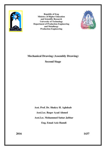
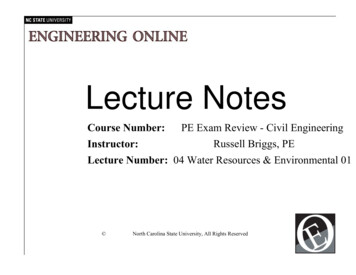
Practical 2. Water supply and Sanitary fixtures - diagramsCivil Engineering Drawing-4-
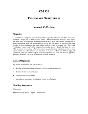
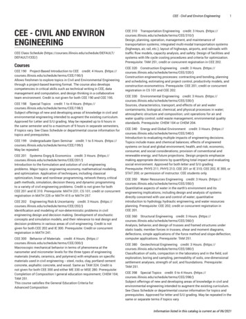
Practical 3. Electrical Installations – diagramsCivil Engineering Drawing-5-
Civil Engineering Drawing1.2DOORS:Doors are the means to provide access to the rooms of a building.A door consists of a frame and one or two shutters or leaves.Accordingly they are called as single shuttered or double shuttered door.Door frame consists of two vertical members called styles andtwo horizontal members one at top called top rail and one bottom rail orsill or threshold. Now-a-days the bottom rail is omitted and made to flushwith floor level. The top tail is projected beyond the styles by about150mm and these projections are known as horns. These are built intomasonary fro keeping in position. M.S. Clamps of flat iron about 300mm 50mm 6mm are fixed to the vertical styles on the outerside known as“Hold Fasts” in the shape of letter ‘Z’. These are embedded into themasonary wall to hold the frame in position. When bottom member (sill)is not provided, the vertical members (styles) should be inserted in thefloor finish by about 40 mm to 50mmShutter for the door frame may be fully panelled or partly glazedand partially panelled with one or two leaves or shutters. In fully panelledshutter the no. of panels may be 3,4 or 6 as per the design and otherpractical considerations. In the case of door shutters, the horizontalmembers are called as rails (top, bottom, lock and frieze). All other railsfixed between the lock rail and top rail are called frieze rail. Thecontinuous vertical members of door frame called as styles or stiles.These styles and rails jointed to each other at both ends by mortise andtenon joints. The bottom and lock rails are made wider than the top orfrieze rails. The center of the lock rail shall be so placed that its centerline is at a height of 850mm from the bottom of the shutter.The joints between the panel and frame shall be tongued andgrooved joints. Grooves are formed along the inner edges of the stilesand rails to receive the panel. The depth of groove is equal to thethickness of panel. As per IS1003; the minimum width and thickness ofpanel shall be 100mm and 15mm respectively. For double leaf shutter,when closed, one leaf overlaps the other vertically as a rebated joint. Inorder to keep the both shutters in the same plane, rebates 8 to 10mmwide and in depth equal to half thickness of a shutter for a square typeare cut as for IS:6198.I.S.1003 RECOMMENDED SIZES FOR DOORS AND WINDOWS:a) Vertical stile, top and frieze rail width:150 3mmb) Lock rail width:150 3mmc) Bottom rail width:200 3mmd) Mounting width:100 3mm-6-
Civil Engineering Drawinge) Glazing bar:40 1mmf) Thickness for all members:35 1 or 40 ecifications) doors and windows are indicated by following letters.D DoorW WindowV VentilatorS Single shutterT Double ShutterP Two PanelsR Three PanelsQ Four PanelsFOOTINGS:The portion of the building constructed above the ground level issuper structure and below the ground level is substructure or foundation,which will distribute the structural load over the large area. In the case ofload bearing walled structure, the size of wall is increased by means offootings of stone masonary or brick masonary and finally rest onconcrete bed of required size.Footings are the steps provided under the load bearing walls byequal increase on eitherside. The number of footings depends upon thedepth of foundation. The increase in width provided on either side of wallface is known as off-set. The depth of the foundation is the verticalheight below ground level upto the bottom of the concrete bed.Individual masonary pillars are constructed with offsets on all foursides to provide number of footings. This entire masonary structure restson concrete bed of required size, which distribute the load intensity onthe sub-soil at low magnitude than the safe bearing capacity of subsoil.Such a foundations are known as isolated footing foundation.Plinth is the portion of the structure between the surroundingground level and the surface of the floor level immediately above theground is termed as plinth. The level of the plinth is usually called asplinth level and the built up area at the floor level is known as plinth area.The plinth height in any case shall not be less than 450mm.The depth of the foundation depends upon as per NBC and shallnot be less than 500mm.1.2.3.4.Bearing capacityShrinkage and swelling properties of soilDepth of water-tableDepth of frost penetration-7-
Civil Engineering DrawingThe width of the foundation depends upon the safe bearingcapacity, load coming on the soil. The width of foundation B 2T 2fwhere ‘f’ offset provided.Generally the concrete offset ‘f’ shall be 150mm. In case of brickmasonary offset 1/4 th brick length (i.e., 50mm) and thickness shall bemultiples of brick thickness (100mm, 200mm, 300mm, 400mm etc).In case of stone masonary offset ‘f’ shall be 75 to 100mm andthickness may be 150 to 200mm.Thickness of concrete foundation:By thumb rule d 5/6 T where ‘T’ Thickness of wall in super structure.Super structure:The portion of building above ground level is called superstructure. This includes masonary walls, columns, steps, doors,windows, ventilators, lintels, sunshades (chajjas), staircase, roof,weather proof course, parapet wall etc.Lintels:Lintels are small beams, which are of reinforced cement concretein present construction provided over small opening like door, window,almairahs etc. Generally 150mm thick and width equal to wall width areprovided.Sunshade:Sunshade is sloping or horizontal R.C.C. cantilever slab providedover openings on external walls to provide protection from sun and rain.Balcony:Balcony is horizontal projection including a handrail or balustradeto serve as passage or sitting out place. As per IS:4912, the verticalheight of handrail for balconies and verandahs shall be 1000mm.Portico:Portico or porch canopy is covered surface supported on pillars orotherwise for the purpose of pedestrian or vehicular approach. Generallythe height of portico slab shall be 2.1m.-8-
PRACTICAL 4 : Draw the following FULLY PANELLED DOORCivil Engineering Drawing-9-
PRACTICAL 6 –Isolated R.C.C.Square FootingPRACTICAL 5 - Fully Panelled WindowCivil Engineering Drawing- 10 -
PRACTICAL 7 - cross section of load bearing wallCivil Engineering Drawing- 11 -
Civil Engineering DrawingCHAPTER 2BUILDING DRAWINGA building may be residential or public building. The plan, section alonggiven vertical plane and elevation gives the details of building.Plan:Plan of building represents a horizontal section of building atgiven height seen from top. It is a general conventional to imagine thatthe building has been cut down by a horizontal plane at the sill level ofthe window and is seen from the top after removal of so cutpart. Theplan shows the arrangement of rooms, varandah or corrider, position ofdoor, and window and other openings along with their respective sizes.The dimension of the room indicated as Breath x LengthIn the case of Varandah’s, the given dimension upto the end ofVarandah retaining wall and the position of beams, sunshades, portico,ventilators which are above sill level of window are shown with dotted orbroken lines.Line diagram is the sketch generally not drawn to particular scalealso known as line sketch. The relative positions of all elements likerooms, doors, windows are clearly shown inside to inside. From thegiven specifications, the thickness of wall in super structure shall betaken to draw the fully dimensioned plan to a convenient scale.Section :Section is also known as vertical section and sectional elevationor cross section. It is imagined that a finished buildings is cut verticallyalong a line so that the building is separated into two portions along theimagined vertical plane right from top of the building to the lowest part offoundation. The view that can be seen while travelling along thisimaginary vertical plane when loo
1.0 CONVENTIONAL SIGNS AND SYMBOLS: Conventional signs are used to represent the particular item like stone masonary, brick masonary, concrete etc in the section of drawing. (i.e.,) when the materials are cut by any imaginary plane. Conventional symbols are provided to indicate doors, windows, their fixing, movement of shutters. When they are cloud or opened, various water supply and