Transcription
Pipelines 2013 ASCE 2013Development History and Characteristics of the Bar-Wrapped Concrete CylinderPipeBy: Henry Bardakjian1, P.E. and Mike Murphy2, P.E.1Consulting Engineer, 1331 N. Maryland Ave, Glendale, CA 91207Email: hbardakjian@gmail.com2Chief Engineer, NOV Ameron, 10681 Foothill Blvd, Rancho Cucamonga, CA 91750Email: Mike.Murphy@nov.comABSTRACTBar-Wrapped Concrete Cylinder Pipe (CCP), and the reasons why its configurationenhances its structural performance, may not be widely understood even though it has along history of service. CCP steel reinforcement consists of a steel cylinder and acontinuous mild-steel bar helically wrapped around the cylinder. CCP also has acentrifugally–cast concrete or cement mortar lining and a dense cement mortar coatingwhich encases the steel cylinder and bar reinforcement.In addition to the steel cylinder, the bar reinforcement provides the balance of steelreinforcement for internal pressure design and it transforms the pipe wall into acomposite structure by mechanically locking the mortar coating tightly against the steelcylinder; this feature was identified during initial testing for the development of the pipeand its specifications. This composite construction increases the pipe’s stiffness and theexternal load-carrying capacity since it increases the ring flexural strength of the pipe,which in combination with the passive earth pressure on the sides of the pipe resists theexternal loads by limiting pipe deflection. The composite construction also increases thepipe’s rigidity and resistance to physical damage and corrosion which are very desirableattributes for water transmission pipelines.The history of CCP and its development milestones since the introduction of the productin 1942 by a US West Coast pipe manufacturer (American Pipe and ConstructionCompany whose name was changed later to Ameron) will be presented; in the late 1940’sother pipe manufacturers started producing CCP. Pipe diameters were initially limited to42 inches and gradually increased to 72 inches as more performance record wasdeveloped. CCP development coincided with the use of Carnegie Steel joints with rubbergaskets on the US West Coast in 1940. Performance testing by American Pipe andConstruction Company and a few agencies, and early CCP standards prior to thedevelopment of the AWWA C303 Standard are reviewed.This paper presents the design concepts of CCP and details its complete componentsincluding the joints. The paper also reviews the performance record of CCP and a fewmajor installations. Good practice installation recommendations are also given.340
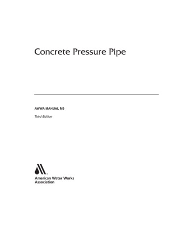
Pipelines 2013 ASCE 2013INTRODUCTIONBar-wrapped concrete cylinder pipe (CCP) is a semi- rigid pressure pipe designed as acomposite structure combining the tensile strength of steel with the compressive strengthand corrosion–inhibiting properties of portland cement mortar. Components of CCP areshown in Figure 1. The components are: a steel cylinder (A) with steel bell and Carnegiespigot rings (B) and (C) welded at the ends is lined with centrifugally cast cement mortaror concrete (D). A continuous mild steel bar (E) is helically wrapped around the cylinderand secured by welding to the joint rings at each end. A dense cement mortar coating (F)encases the cylinder and bar reinforcement. A round rubber gasket (G) is placed in anannular groove in the spigot ring just prior to field assembly. A grout band (H) wrappedaround the joint and firmly strapped on both sides after field assembly serves as the moldfor cement mortar grout (I) poured in the exterior joint space. The interior joint space ispointed (filled) with cement mortar (J).HISTORY AND MILESTONES DURING DEVELOPMENT OF CCPDuring World War II, there were shortages of steel coil and plate for use in domesticinfrastructure; the availability of bar reinforcement was slightly better. Therefore,American Pipe and Construction Company (American), a cement mortar-lined-andcoated steel pipe manufacturer, whose name was later changed to Ameron in 1970,developed a pipe in 1942 with bar reinforcement to supplement the steel cylinder areaFigure1. Components of Installed CCP.341
Pipelines 2013 ASCE 2013required to resist the internal hydrostatic pressure. The advantages of this practice, whichresults in a composite wall structure were demonstrated through product testing and fieldexperience. Other major milestones are: The use of Carnegie type gasketed joints, which American had acquired the rights forits use in 1937, and the design and development by American of its helical weldingmachines for forming continuous steel cylinders up to 3/16-inch in the late 1940’sand up to 3/8-inch thickness in the late 1950’s were fundamental to the success ofCCP as a product. The City of San Diego was one of early users of CCP in the early 1940’s for theirwater system for pipe diameter up to 42 inches. Other agencies followed suitincluding the United States Bureau of Reclamation (USBR) in 1949. American developed its own design and manufacturing guidelines until the first USFederal Specification SS-P-00381 was issued on April 2, 1953 which was supersededwith SS-P-381 on September 14, 1955. The standard initially covered pipe diametersup to 36 inches and was later extended to include diameters up to 42 inches. TheFederal Specification was revised as SS-P-381A in 1967. American conducted a series of comprehensive tests on 60-inch diameter CCP in1953 which were witnessed by an independent inspection company. The test resultsconvinced the Empressa De Acueducto De Bogotá in Colombia to allow CCP as analternate for the Tibitoc water supply system consisting of approximately 13 miles of60-inch diameter pipeline in 1955. American was successful in securing the project;this project was instrumental for extending the CCP pipe diameter range from 42inches to 60 inches. In 1970 the name of American Pipe and Construction Company in North Americawas changed to Ameron. The name in Columbia could not be changed. Ameron gradually extended their manufacturing capabilities, particularly the helicalforming and welding machines with forming tubes in 1980’s up to 0.50 inch steelcylinder thickness which was necessary to produce larger diameter and higherpressure class CCP. The CCP diameter range was extended to 72 inches after the AWWA C303 standardwas issued in 1970 and the USBR standard in 1972 and US Federal SpecificationsSS-P-381B in 1979. The USBR have over 300 miles of large diameter CCP projectsin their systems. The diameter range in the AWWA C303 was extended gradually,through revisions, to 72 inches. Since introduction of CCP in 1942, Ameron and other pipe manufactures such asUnited Concrete Pipe, Gifford-Hill American (became Hanson in 1994) and othershave supplied several thousand miles of CCP pipelines in North and South America,the Middle East and Far East.342
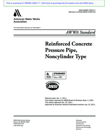
Pipelines 2013 ASCE 2013PERFORMANCE TESTING OF CCPThis paper covers tests conducted by Ameron (or American until 1970) only and does notcover tests conducted by other CCP manufacturers. The following describes some of thetesting: Many load deflection tests were conducted by Ameron in the 1940’s by encasing thepipe in sand within a frame and then applying an external load by load cells withhydraulic rams through a beam on top of the frame. The pipe deflections weremeasured through spring loaded dial indicators from inside the test pipe; the set upwas similar to the set up shown in Figure 2 except the test pipe was completelyencased with sand. The objective of such tests was to fine tune the ratio of barreinforcement area to the cylinder area and corresponding composite wall properties.Results of one of the test series were presented in October 24, 1951 at the AWWACalifornia Section Meeting in San Francisco (White 1952). External crushing strength (external hydrostatic pressure) tests were conducted by oneof the users (East Bay Municipal Utility District, Oakland, CA) of bar-wrapped steelpipe with cement mortar lining and coating. The results were presented in the sameOctober 24, 1951 meeting which is referenced above; these tests have shown that thebar-wrapped steel pipe with cement-mortar lining and coating can withstand fullvacuum without damage (Paul et al, 1952). The 36-inch diameter pipe was able towithstand 76 psi external pressure before collapsing. Ameron conducted three phase comprehensive tests on 60-inch diameter CCP inAugust 1953 up to January 1954 which was witnessed by Smith-Emery Inspectionand Testing Company. The three test phases and their objectives are listed below.1. The first phase consisted of conducting hydrostatic pressure tests with testpipe having different ratios of bar to cylinder steel areas. The results showedthat the bar reinforcement is more effective than the cylinder alone indistributing the strains in the coating due to internal hydrostatic pressureswithout visible cracking.2. The second phase consisted of three buried pipe sections with 4 ft cover plusadditional external loading; two pipe sections were joined before backfillingand the third section was installed and backfilled separately with an inspectionpit separating both assemblies. The objective, besides observing the structuralperformance of the lining and coating under external loading conditions, wasto demonstrate that the joint can withstand the external load, and the joint hasthe ability to transfer load from one pipe to another. The tests were repeatedafter removal of the backfill and disassembly of the two pipe sections andsubsequent reinstallation of the two sections separately with an inspection pitbetween them; this was performed to ensure that the pipe sections do notsupport each other under external loading.343
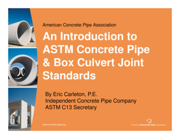
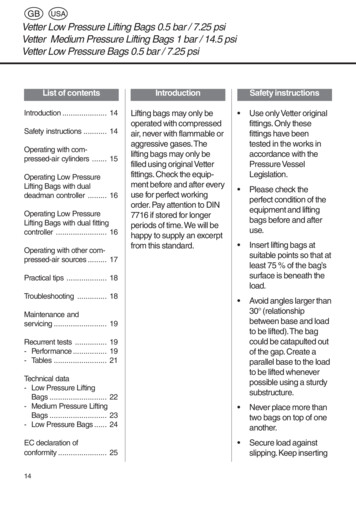
Pipelines 2013 ASCE 2013344Figure 2. Set up for Sand-Bearing Load/ Deflection Tests3. The third phase consisted of two assembled pipe sections with bulkheads atthe ends and tie rods across to hold the internal pressure thrust afterpressurizing. The joint area was subjected to a concentrated load to force pipedeflection in the joint area. The objective was to demonstrate thewatertightness of the CCP joint under the allowable pipe deflections: the jointwas watertight under the maximum loading of the test equipment, whichproduced more than twice the design allowable pipe deflection. Ameron conducted many performance related load deflection tests in the 1960’sand 1970’s. One notable large diameter CCP test was conducted on 66-inchdiameter CCP where the pipe was buried in a trench with compacted loambackfill, 3 ft. cover, and additional external load applied. The interior profiles ofdeflected pipe, plotted to an exaggerated scale, are shown in Figure 3; the trenchprofile and external applied load, W, is also shown. Under maximum appliedload, equivalent to 17.5 feet of soil cover, both vertical and horizontal pipedeflections were 0. 5 %. In 1989 Ameron conducted hydrostatic and sand-bearing tests on 54-inchdiameter CCP, which were witnessed by the USBR and the Metropolitan WaterDistrict of Southern California. The stress/strain curve for hydrostatic test resultsfor one of the of the 54-inch diameter CCP test pipe sections is given in Figure 4.Strain gauges were attached to the cement-mortar coating, the steel cylinder andbar reinforcement. The applied pressure and corresponding strain reading wererecorded by a data logger. Only hairline cracks were observed in the cementmortar coating. The maximum theoretical stress in the steel, corresponding to theapplied hydrostatic pressures, was approximately 27,000 lb/inch2 when the testwas terminated.
Pipelines 2013 ASCE 2013 Figure 3. Deflection measurements for buried66” CCP in a test installationIn 1999, sand-bearing pipe deflection tests, which were sponsored by Las VegasValley Water District (LVVWD), were conducted by Ameron on 36-inchdiameter and 54-inch diameter steel cylinder pipe with cement mortar lining andcoating with and without bar reinforcement (Bardakjian et al, 2001). Refer toFigure 2 for the test set-up which shows the 36-inch and 54-inch diameter testFigure 4. Stress/Strain curve for a hydrostatic test for54” CCP345
Pipelines 2013 ASCE 2013346pipe side by side. The uniqueness of these tests is that the loads were taken to themaximum capacity of the testing machines or until the lining compression failureoccurred. In case of the 36 inch diameter pipe with bar reinforcement, the liningcompression failure occurred at 6.5% deflection where the steel may have alsoreached the yielding point. The maximum load applied for the 54-inch diameterpipe resulted in 5.8% deflection with no compression lining failure. Figures 5 and6 show the sand bearing load versus the pipe deflection curves for one 54-inchtest pipe section with minimum bar reinforcement and one 54-inch test pipewithout bar reinforcement, respectively; both pipes have the same steel area. Themaximum load applied for the test pipe with bar reinforcement was approximately8000 lb/ft compared to approximately 5000 lb/ft for the test pipe without barreinforcement at approximately 5.8% pipe deflection; this verified theeffectiveness of the bar reinforcement for improving the structural performanceof the pipe.CCP CHARACTERISTICSThe circumferential mild steel bar, which is helically wrapped around the cylinder at atensile stress of 8,000 to 10,000 psi, provides the balance of the steel required to resisttensile hoop forces and it also reinforces the mortar coating and locks it tightly againstthe steel cylinder so that the cylinder, bar, and coating act as a composite structure.Without the bar reinforcement, the wall stiffness will be the sum of the stiffnesses of thethree laminar rings, (the lining, the cylinder, and the coating), which is significantly lessthan the stiffness of the composite wall construction. Other characteristics are: Wrapping the steel bar under some tension produces moderate compressive stress inthe steel cylinder and cement-mortar lining, thereby increasing the rigidity of the pipeand reducing the effects of drying shrinkage.120 Sand Bearing Loading of 54-inch Mortar-Coated and -LinedBar-Wrapped Welded Steel Pipe (4D)10,0009,000Total Load per Linear Foot, lbf/LF8,000Steel on upper boxtouchingat all 4 corners7,0006,0000.01" coating crackon SE side0.01" coating crackon SW side5,0004,000Multiple continuouslining crackson crown3,000Vertical westHorizontal westVertical EastHorizontal East2,0001,0000-4-3-2-10Pipe Deflection, inchFigure 5. Load deflection curves for 54” CCP1234
Pipelines 2013 ASCE 2013Figure 6. Load deflection curves for 54-inch mortar lined and coatedsteel pipe without bar reinforcement. The composite construction of CCP increases the pipe rigidity and resistance tophysical damage, during both handling and installation.CCP is inherently corrosion-resistant due to its composite construction and to theunique protective properties of portland cement mortar.The bar reinforcement in CCP is more effective than the cylinder alone to distributethe strains in the coating due internal pressure hoop stress.DESIGN CONCEPTS of CCPCCP is designed as a composite steel and cement mortar structure. Steel cylinderthickness, bar diameter, and bar spacing are controlled within specified limits to ensurethe integrity of the composite design. Hydrostatic pressures are resisted by the steelcomponents of CCP, the steel cylinder and circumferential steel bar. External loads areresisted by the ring flexural strength of the pipe and by the passive earth pressure on thesides of the pipe. Both maximum circumferential stresses and maximum pipe deflectionsare held to values which will not impair the structural and protective properties of thecement mortar lining and coating. CCP is a semi-rigid pipe, designed in conformancewith AWWA C303 Standard and AWWA Manual M9.PERFORMANCE of CCPSince its introduction in 1942, several thousand miles of CCP pipelines have beeninstalled in North and South America, the Middle East, and the Far East. Theperformance record has been very good with very few issues, which have been mainlydue to improper installations. A 66-inch diameter CCP installation in 2004 is shown inFigure 7 for a project for San Diego County Water Authority. The trench was excavated347
Pipelines 2013 ASCE 2013mainly through rock foundation by ripping and blasting and the excavated rocks wereprocessed into crushed rock and used as bedding material.The following are a few examples of recent large diameter CCP projects:1. A three phase project in Saudi Arabia, the Al-Hunayy Water transmissionproject, consisted of 320 miles of 48-inch and 54-inch diameter CCP pipelinewas completed in 2006.2. In 2003 and 2004, 52 miles of large diameter, 54 to 72- inch diameter CCPprojects were completed in California and Arizona. Some of these projectsutilized testable gasketed joints.INSTALLATION RECOMMENDATIONSThere have been a few isolated issues with a few CCP projects, which were the result ofinstallations without any bedding under the pipe on unyielding foundations or no or poorhaunch support for larger diameter pipe. A similar test to that shown in Figure 3 wasconducted to simulate poor haunch support. Instead of compaction by tamping, loambackfill material, which is not self-draining, was water jetted to produce the poor haunchsupport. At the maximum load applied, equivalent to 7.5 ft of cover, the verticaldeflection was 2.6%, and reverse curvature damaging the lining and coating occurred inthe bottom of the pipe. The following are a few installation recommendations: The use of water jetting in cohesive backfill soils is not recommended; water jettinghas been used successfully for consolidation of self-draining cohesionless soils.The installation of pipe without any bedding on unyielding foundations is not a goodpractice and will result in pipe damage. The bedding material under the pipe shouldFigure 7. Installation of 66-inch diameter CCP348
Pipelines 2013 ASCE 2013include at least a 2- inch layer of loose sand or unconsolidated material that canprovide a yielding foundation for better external load distribution.CONCLUSIONS and OBSERVATIONSThe following are a few conclusions and observations: The Composite wall construction of CCP is a desirable feature since it increases thepipe stiffness and consequently its external load carrying capacity, due to the increasein the ring flexural strength of the pipe.The composite wall construction of CCP also increases its resistance to physicaldamage, over deflection, and corrosion, which are very desirable attributes for watertransmission pipelines.The bar reinforcement of CCP is more effective than the cylinder alone in distributingthe strain in the coating resulting from internal pressure. This is similar to the barsteel area used in reinforced concrete cylinder pipe, where a portion of the requiredsteel area has to be provided as bar reinforcement.REFERENCESAmerican Water Works Association (AWWA, 2008). “Concrete Pressure Pipe, BarWrapped, Steel Cylinder Type”, AWWA C303 Standard, AWWA, Denver, CO.American Water Works Association (AWWA, 2008). “Concrete Pressure Pipe”, Manualof Water Works Practices M9, Third edition, AWWA, Denver, COBardakjian, Henry .H, and Mollus, Shawn P. (2001). “Deflection Limits of Mortar Linedand Coated Welded Steel Pipe Under 120º Sand-bearing Loading”, ASCE PipelineConference, Pipelines 2001, Advances in Pipeline Engineering and Construction,San Diego, CA, July 2001.Paul, Leslie and Owen F. Eide, (1952). “Crushing Strength of Steel Pipe Lined andCoated with Cement Mortar,” Jour. AWWA, 44:6White, H.L, (1952). “External Loads on Pipe with Cement Mortar” Jour. AWWA 44:6Federal Specification SS-P-381B (1979). “Pipe; Pressure, Reinforced Concrete,Pretensioned Reinforcement (Steel Cylinder Type”, Federal Supply ServicesUnited States Department of the Interior, Bureau of Reclamation (1972). “StandardSpecification for Pretensioned Concrete Cylinder Pipe”,
2Chief Engineer, NOV Ameron, 10681 Foothill Blvd, Rancho Cucamonga, CA 91750 Email: Mike.Murphy@nov.com ABSTRACT Bar-Wrapped Concrete Cylinder Pipe (CCP), and the reasons why its configuration enhances its structural performance, may not be widely