![[MI 611-148] 871PH PH/ORP Sensors And Accessories - Installation And .](/img/36/mi-611-148.jpg)
Transcription
MI 611-148InstructionAugust 2008871PH pH/ORPSensors and AccessoriesInstallation and Maintenance
MI 611-148 – August 2008
ContentsFigures. vTables. vi1. Introduction . 1Dangers, Warning, and Cautions . 1Theory of Operation . 2pH Measurement . 2ORP Measurement . 2Reference Documents . 2Standard Specifications . 4Sensor-Analyzer/Transmitter Compatibility . 5Temperature Limits . 5Electrical Safety Specifications . 6Sensor Identification . 9Model Code . 102. Installation .Removing the Sensor Protection Cap .Measuring Electrode Installation .General Sensor Installation Guidelines .Flow Chamber Installation .Plug Installation .Bushing Installation .13131314141617Tee Installation .Electrode Protection Sleeve Installation .Submersion/Immersion Installation .Ball Valve Assembly Installation .Installing the Ball Valve Assembly Into the Process .Connecting the Sensor to the Insertion Shaft Assembly .Installing the Insertion Shaft into the Ball Valve .Removing and Replacing a Sensor .Electrode Cleaning System (ECS) .Wiring .Cable Variations .Cable Length .Connections to Analyzer or Transmitter .Variopin Connectors .1818192020212123242424242627iii
MI 611-148 – August 2008ContentsRemote Preamplifier . 273. Maintenance.Electrode Inspection .Electrode Cleaning .Cleaning a Glass Electrode .Cleaning an Antimony Electrode .Cleaning an ORP Electrode .Cleaning the Reference Junction .Storing a Sensor .Measuring Electrode Replacement .Removing the Old Electrode .Removing a Broken Glass Electrode .Installing the New Measuring Electrode .Refilling the Reference Cavity .Reference Junction Replacement .Removing the Reference Junction .Refilling the Reference Cavity .Installing the Reference Junction .29292929293030303030313233333334344. Troubleshooting. 37Index . 41iv
Figures123456789101112131415871PH Sensor Identification .Flow Chamber Installation .Plug Installation on Flow Chamber .Twist-Lock Bushing Installation .Twist-Lock Tee Installation .Electrode Protection Sleeve Installation .Submersion/Immersion Installation .Ball Valve Assembly .Insertion Shaft Assembly .Ball Valve Shaft Installation and Removal .Cable Lengths for Cable With Pin Lugs .Cable Lengths for Cable With Generic Connector .Cable Lengths for Cable With Variopin Quick Connector .Removing Measuring Electrode .Removing the Reference Junction .91517181819192121232425253134v
Tables1234567891011121314Maximum Pressure and Operating Temperature Limits for Sensor with Ryton Body .Maximum Pressure at Various Operating Temperaturesfor Sensor with CPVC Body .871PH Sensor Certification .871PH and Transmitter/Analyzer Loop Certifications .Flow Chamber Specifications .Plug Specifications .Bushing Specifications .Ball Valve Assembly Specifications .Analyzer and Transmitter Connections .Standard Temperature Cable Wiring - Sensor Without Preamplifier .Cable Wiring - Sensor With Preamplifier .High Temperature Cable Wiring - Sensor Without Preamplifier .Process Temperature vs. RTD Resistance .Sensor Troubleshooting .566715161720262626273739vi
1. IntroductionThe 871PH Sensor is used with Foxboro 870PH and 870ITPH Transmitters and 873PH,873APH, 873DPX, and 875PH Analyzers. The 871PH Sensor permits multiple-purpose usewith only one basic sensor. The sensor uses one of several electrodes as the sensitive element and awetted, nonflowing ceramic disc as the primary reference junction. These components aremounted in the body of the sensor assembly with a temperature compensating device.Dangers, Warning, and Cautions! DANGERWhen performing maintenance, wear appropriate protective clothing, includingsafety goggles. Escaping chemicals under pressure can cause severe injury includingblindness.! WARNINGUse care when connecting and disconnecting high pressure service connections. Toavoid severe injury to personnel or damage to equipment, use proper gloves andfollow the recommended procedures.! WARNINGWhen processing hazardous liquids, follow the recommended procedures. Failure todo so could result in injury to personnel and damage to equipment.! WARNINGUse only Foxboro recommended spare parts. Substitution parts could result indamage to equipment, damage to the process, and/or injury to personnel. Also safetycertification may also be compromised by the substitution of improper parts.! WARNINGAntimony is a toxic material. When an antimony electrode is installed, avoid contactwith the surface of the antimony pellet. If skin contact is made with the antimonypellet, wash the contacted skin area with soap and water. Refer to MSDS051.! CAUTIONUse care when handling and assembling sensor components (e.g., glass electrodes,O-rings, etc.) to prevent damage.1
MI 611-148 – August 20081. IntroductionTheory of OperationpH MeasurementpH indicates the concentration of hydrogen ions (H ) present in aqueous solution. Since theconcentration of hydrogen ions determines the degree of acidity or alkalinity of the solution, pHis also said to be a measure of acidity or alkalinity. pH is defined as the negative logarithm of thehydrogen ion concentration:pH -log [H ]The pH scale ranges from 0 to 14, with a pH of 7 being neutral, a pH less than 7 being acidic,and a pH greater than 7 being basic (alkaline).Measurement of pH by the 871PH sensor is accomplished by immersing the probe, whichconsists of integral pH and reference electrodes, in the process solution. The pH electrode, whichis sensitive to hydrogen ions in solution, develops an electrical potential proportional to pH. Thereference electrode, which consists of Silver/Silver Chloride connected to the process via aPotassium Chloride salt bridge through a ceramic junction, provides a stable reference potentialagainst which the glass electrode potential is measured. These two electrodes constitute a galvaniccell having a millivolt output proportional to the pH of the solution.ORP MeasurementORP is a measure of the electrical potential of a reaction known as an oxidation-reduction (redox)reaction. A redox reaction is one in which one component loses one or more electrons (oxidation)while another component gains one or more electrons (reduction). The oxidation-reductionpotential is related to the ratio of oxidation activity to reduction activity. By convention, asolution that contains an excess of oxidizing agent has a positive ORP, and a solution that containsan excess of reducing agent has a negative ORP.Measurement of ORP is accomplished by immersing the 871PH sensor, configured with a gold orplatinum electrode, in a solution along with its integral Silver/Silver Chloride reference electrode.This probe develops a millivolt output (similar to pH measurement) that is proportional to theratio of oxidizing agent to reducing agent, or ORP.Reference DocumentsDocument(a)DescriptionDP 611-113DP 611-121871PH pH and ORP SensorsMounting Accessories used with 222 and 871PH pH and ORP SensorsDP 611-122DP 611-123Ball Valve Assembly for 222 and 871PH pH and ORP SensorsOptional Containment Device for 1, 2, or 4 in Spool Piece for 222 and 871PH pHand ORP SensorsElectrode Cleaning System (ECS); Flow-through Spool Piece for 222 and 871PHpH and ORP SensorsDP 611-1402
1. IntroductionDocument(a)DP 611-141MI 611-155MI 611-165MI 611-190MI 611-191MI 611-206MI 611-208(b)MI 611-211MI 611-125MI 611-225MI 611-229PL 611-014MI 611-148 – August 2008DescriptionElectrode Cleaning System (ECS); Flow-through Spoolpieces and SubmersibleAssemblies for use with 222, 871PH, 871A, and 871DO Sensors870PH pH and ORP Transmitters873PH Series Electrochemical Analyzers for pH or ORP Measurement873DPX Series Electrochemical Analyzers for Dual pH, ORP, or ISE Measurement873APH ACE Series Electrochemical Analyzers for pH MeasurementIntrinsic Safety Connection Diagrams and Nonincendive CircuitsElectrochemical Products Safety Information (for European installations)870ITPH Intelligent Transmitter for pH, ORP, and ISE MeasurementsElectrode Cleaning System (ECS) for 871A, 871DO, 871PH and 222 Series Sensors875PH Intelligent Electrochemical Analyzers for pH, ORP, or ISE MeasurementsRemote Preamplifier Junction Box, BS811MR871PH pH/ORP Sensors(a) Documents are available on line at www.foxboro.com (pull down Products menu and select Documentation(b)If document is not yet available on website, contact Invensys Process Systems for current availability.3
MI 611-148 – August 20081. IntroductionStandard SpecificationsItemAutomatic TemperatureCompensation (ATC) LimitsSensor AssemblyImmersion/SubmersionDepthMeasuring ElectrodesMeasuring Electrode BodyMaterial:Glass pH*:Antimony pH:Platinum ORP:Gold ORP:Measuring Electrode O-ringsSolution GroundSpecification-5 and 125 ºC (20 and 255ºF)Minimum: 50 mm (2 in)Maximum: 6 m (20 ft)Plug-in, interchangeableRyton or ptfe body as specifiedRyton or ctfe body as specifiedRyton or ctfe body, as specifiedRyton or ctfe body, as specifiedStandard: Viton; Optional EPDM and ChemrazTitanium (Grade 2 CP), Carpenter 20 Cb-3, 316L Stainless Steel,Monel 400, or Tantalum, as specified. The solution ground stud alsoacts as a keeper for securing electrodes in the sensor assembly.Reference ElectrodeNonflowing, with Ag/AgCl internals and saturated potassiumchloride (KCl) electrolyte.Reference Junction andCeramic/Ryton,Body MaterialsCeramic/ptfe, orCeramic/Double Junction, Ion Barrier, pvdfReference Electrode O-rings Standard: Viton; Optional EPDM and ChemrazSensor Body MaterialRyton or CPVC housing, as specified; Viton O-ring (see above forelectrodes and solution ground).Maximum Pressure andSee Table 1, “Maximum Pressure and Operating Temperature LimitsTemperature Limitsfor Sensor with Ryton Body,” on page 5, and Table 2, “MaximumPressure at Various Operating Temperatures for Sensor with CPVCBody,” on page 6.Electrical ClassificationSee Tables 3 and 4.Standard CableIntegral 6 m (20 ft) screened, PVC jacketed, terminated with straightpin lugs for connection to all Foxboro analyzers and transmitters.Options are available.PreamplifierIntegral, encapsulated, differential high impedance preamplifier iscontained in the 871PH-1, -2, -3 and -4 sensors.Installation DimensionsSee DP 611-113.ElectromagneticThe 871PH Sensor, when its cable is connected through rigid metalCompatibility (EMC)conduit as recommended for 873PH, 873APH, 873DPX (220 V ac,240 V ac Metal Enclosures only), 870ITPH Transmitters, or 875PHAnalyzers, complies with the requirements of the European EMCDirective 89/336/EEC.*Spherical, flat ruggedized, or domed high temperature glass (has high stability Ag/AgCl internals)4
1. IntroductionMI 611-148 – August 2008Sensor-Analyzer/Transmitter Compatibility871PH-1, -2:Compatible but does not support the diagnostic features of the870ITPH Transmitter and 875PH Analyzer.871PH-3, -4, -5, -6:Compatible with 870ITPH Transmitter and 875PH Analyzer only.Temperature LimitsTable 1. Maximum Pressure and Operating Temperature Limits for Sensor with Ryton BodyBall Valve or Submersible InstallationMeasuringElectrode TypeFlat Glass pHSpherical GlasspHDomed Glass pHAntimony pHORPMaximumPressure1 MPa(150 psi)0.7 MPa(100 psi)0.7 MPa(100 psi)1 MPa(150 psi)1 MPa(150 psi)TemperatureRange(a)-5 to 80 C(20 to 175 F)-5 to 80 C(20 to 175 F)0 to 80 C(32 to 175 F)-5 to 80 C(20 to 175 F)-5 to 80 C(20 to 175 F)In-Line InstallationMaximumPressure1 MPa(150 psi)0.7 MPa(100 psi)0.7 MPa(100 psi)1 MPa(150 psi)1 MPa(150 psi)TemperatureRange-5 to 85 C(20 to 185 F)-5 to 100 C(20 to 212 F)0 to 121 C(32 to 250 F)-5 to 125 C(20 to 255 F)-5 to 125 C(20 to 255 F)(a) Temperature range for sensors with no preamplifier and with a high-temperature cable is the same as that for InLine Installation.NOTEMaximum allowable temperature and pressure may be limited by installationhardware used. Refer also to the temperature and pressure specifications on allappropriate bushings, tees, flow chambers, and ball valve assemblies.5
MI 611-148 – August 20081. IntroductionTable 2. Maximum Pressure at Various Operating Temperaturesfor Sensor with CPVC BodyMeasuringElectrodeTypeBall Valve or Submersible InstallationIn-Line InstallationMaximum Pressure at OperatingTemperatureMaximum Pressure at OperatingTemperatureFlat Glass pH 0.9 MPa(125 psi) at-5 C (20 F)Spherical0.7 MPaGlass pH(100 psi) atDomed Glass -5 C (20 F)pHAntimony pH 0.9 MPa(125 psi) atORP-5 C (20 F)0.9 MPa(125 psi) at-5 C (20 F)0.6 MPa(90 psi) at50 C(120 F)0.3 MPa0.7 MPa(50 psi) at(100 psi) at80 C-5 C (20 F)(175 F)0.3 MPa(50 psi) at80 C(175 F)0.1 MPa(15 psi) at100 C(212 F)0.9 MPa(125 psi) at-5 C (20 F)NOTEMaximum allowable temperature and pressure may be limited by installationhardware used. Refer also to the temperature and pressure specifications on allappropriate bushings, tees, flow chambers, and ball valve assemblies.Electrical Safety SpecificationsNOTEThese sensors have been designed to meet the electrical safety descriptions listed inTables 3 and 4. For detailed information, or status of testing laboratoryapprovals/certifications, contact Invensys Process Systems.Table 3. 871PH Sensor CertificationTesting Laboratory,Type of Protection, and AreaClassificationATEX Type n energy limited forII 3 GD EEx nL IIC, Zone 2.ATEX intrinsically safe forII 1 GD EEx ia IIC, Zone 0.6Application ConditionsElectricalSafety DesignCodeConnect to instrument per MI 611-208. CS-E/ANNTemperature Class T4 - T6.T110 C - T235 CConnect to instrument per MI 611-208. CS-E/AAATemperature Class T4 - T6.T110 C - T235 C
1. IntroductionMI 611-148 – August 2008Table 3. 871PH Sensor Certification (Continued)Testing Laboratory,Type of Protection, and AreaClassificationApplication ConditionsFM intrinsically safe for Class I;Division 1, Groups A, B, C, and D;Class II, Division 1, Groups E, F,and G; Class III, Division 1.Connect to associated apparatus withcompatible entity parameters perMI 611-206.Temperature Class T4 at 85 C (185 F)maximum ambient.FM nonincendive Class I, Division 2, Connect to associated apparatus withGroups A, B, C, and D; Suitable for compatible entity parameters perClass II, Division 2, Groups F and G; MI 611-206.Class III, Division 2.Temperature Class T4 at 85 C (185 F)maximum ambient.ElectricalSafety DesignCodeCS-E/FAACS-E/FNNTable 4. 871PH and Transmitter/Analyzer Loop CertificationsTesting Laboratory,Type of Protection, and AreaClassificationCSA Class I, Division 2, Groups A,B, C, and D hazardous locations.CSA; ia.CSA intrinsically safe for Class I,Division 1, Groups A, B, C, D;Class II, Division 1, Groups E, F,and G; Class III, Division 1.CSA Class I, Division 2, Groups A,B, C, and D, hazardous locations.CSA Class I, Division 2, Groups A,B, C, and D.CSA suitable for Class I, Division 2,Groups A, B, C, and D; Class II,Division 2, Groups E, F and G;Class III, Division 2.CSA suitable for Class I, Division 2,Groups A, B, C, and D; Class II,Division 2, Groups F and G;Class III, Division 2.CSA ordinary locations.ElectricalSafety DesignApplication ConditionsCodeConnect to 873PH / 873APH. For use with CS-E/CNZenclosure W, X, Y and Z.Connect to 870PH Transmitter. For useCS-E/CA-Awith 871PH style A all configurations.Connect to 870ITPH Transmitter per870ITPH-.CAAMI 611-206. Temperature Class T3C at85 C (185 F) maximum ambient.Connect to 870PH Transmitter. For usewith 871PH style A all configurations.Connect to certified 873PH Transmitter perMI 611-206. Temperature Class T6.Connect to 875PH Transmitter.Supply Voltage -A, -B, -C, E, and -J.Temperature Class T4 at 85 C (185 F)maximum ambientConnect to 870ITPH Transmitter perMI 611-206. Temperature Class T4.CS-A/CN-AConnect to 870PH Transmitter. For usewith 871PH style A all CNZ7
MI 611-148 – August 20081. IntroductionTable 4. 871PH and Transmitter/Analyzer Loop Certifications (Continued)Testing Laboratory,Type of Protection, and AreaClassificationCSA ordinary locations.ElectricalSafety DesignApplication ConditionsCodeConnect to 873PH / 873APH. For use with CS-E/CGZenclosure P, W, X, Y, and Z. Supply voltage A, -J and -E.CSA ordinary locations.Connect to 875PH Transmitter. Supply875PH-.CVoltage -A, -B, -C, E, and -J. TemperatureClass T4A at 85 C (185 F) maximumambientCSA ordinary locations.Connect to 870ITPH Transmitter.870ITPH-.CAA870ITPH-.CNZFM intrinsically safe Class I;Connect to approved 870PH Transmitter CS-E/FB-ADivision 1, Groups A, B, C, and D; per MI 611-206.Class II, Division 1, Groups E, F,Temperature Class T6.and G; Class III, Division 1.FM intrinsically safe Class I, II, and Connect to 870ITPH Transmitter per870ITPH-.FAAIII, Division 1, Groups A, B, C, D, MI 611-206. Temperature Class T4.E, F, and G.FM; n.Connect to 873PH / 873APH. For use with CS-E/FNZenclosure W, X, Y and Z. Supply voltage -A,-J and -E.FM nonincendive Zone 2;Connect to 870PH Transmitter. For useCS-A/FN-ADivision 2.with 871PH style A all configurations.FM nonincendive Class I, Division 2, Connect to 875PH Transmitter. Supply875PH-.FGroups A, B, C, and D; Class II,Voltage -A, -B, -C, and -J. TemperatureDivision 2, Groups F and G; Class Class T4A at 75 C (167 F) maximumIII, Division 2.ambient.FM nonincendive Class I, Division 2, Connect to 870ITPH Transmitter per870ITPH-.FNZGroups A, B, C, and D; Class II,MI 611-206. Temperature Class T4.Division 2, Groups F and G;Class III, Division 2.FM ordinary locations.Connect to 873PH / 873APH. For use with CS-E/FGZenclosure P, W, X, Y and Z.FM ordinary locations.Connect to 875PH Transmitter. Supply875PH-.FVoltage -A, -B, -C, and -J. TemperatureClass T4A at 75 C (167 F) maximumambient.FM ordinary locationsConnect to 870ITPH Transmitter.870ITPH-.FAA870ITPH-.FNZKEMA intrinsically safeConnect to 870ITPH-.EAA or equivalent . CS-E/KA-ECENELEC EEx ia, Zone 0.8
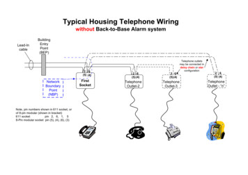
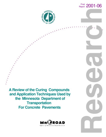
1. IntroductionMI 611-148 – August 2008Sensor Identification871PH-1A1AA2B0319x.xFigure 1. 871PH Sensor IdentificationThe ORIGIN code is the manufacturing date code. In the example 2B0319x.x, 2B means thatthe product was manufactured in the Analytical Division, 03 identifies the year of manufacture,19, the week of manufacture, and x.x, positions for digits of the serial number.9
MI 611-148 – August 20081. IntroductionModel CodeDescriptionRebuildable Style pH/ORP SensorModel871PHSensor Body Material and Diagnostic ConfigurationRyton, Standard Configuration, Integral 6 m (20 ft) Cable, Integral Preamplifier (a)CPVC, Standard Configuration, Integral 6 m (20 ft) Cable, Integral Preamplifier (a)Ryton, Intelligent Configuration, Integral 6 m (20 ft) Cable, Integral Preamplifier (b)CPVC, Intelligent Configuration, Integral 6 m (20 ft) Cable, Integral Preamplifier (b)Ryton, Intelligent Configuration, Integral 6 m (20 ft) Cable, No Preamplifier (b)CPVC, Intelligent Configuration, Integral 6 m (20 ft) Cable, No Preamplifier (b)–1–2–3–4–5–6Measuring Electrode and Body MaterialSpherical Glass, pH, RytonAntimony, pH, RytonPlatinum, ORP, RytonGold, ORP, RytonFlat Ruggedized Glass, pH, Ryton (c)Domed High Temperature Glass, pH, RytonSpherical Glass, pH, ptfeAntimony pH, ctfePlatinum, ORP, ctfeGold, ORP, ctfeFlat Ruggedized Glass, pH, ptfe (c)Domed High Temperature Glass, pH, ptfeNoneABDEFGPQRSTUXSensor Wetted Metallic Parts MaterialTitaniumCarpenter 20 CbAISI Type 316L Stainless Steel (316L ss)MonelTantalum12356Reference Junction and Body MaterialCeramic, RytonCeramic, ptfeCeramic, Double Junction, Ion Barrier, pvdfABDOptional SelectionsCable; Integral to Sensor; Standard and High TemperatureNonstandard Integral Cable Length, standard temperature at 85 C (185 F);(not available with Option -Q) (d)Nonstandard Integral Cable Length, terminated in generic connector plug; standard temperature at 85 C(185 F); specify length; Not available with Options -4, -B, -Q, -H) (d)(e)(f)(g)Standard Integral Cable Length 6 m (20 ft), terminated in generic connector plug; standard temperatureNot available with Options -4, -B, -Q, -H) (e)(f)(g)Integral High Temperature Cable rated 125 C (255 F) (with Sensor Body -5, -6;Not available with Options -5, -7, -Q)-3-5-7-HVariopin Quick Connector on Integral Cable or Sensor BodyIntegral Cable Terminated w/Variopin Quick Connector (not available with Options -4, -5, -7) (f)(j)Variopin Quick Connector Integral to Sensor Body (not available with Options -3, -4, -5, -7) (f)(j)-B-QO-RingsEPDM O-Rings (standard O-rings are Viton)Chemraz O-Rings (standard O-rings are Viton)-E-CMiscellaneous Optional SelectionsNo spade lug terminals attached to end of cable (not available with Option -5, -7, -B, -Q) (h)ptfe Collar-4-TExample: 871PH–1F1A–4(a)Does not support the sensor diagnostic features of 870ITPH Transmitter and 875PH Analyzer.(b)Compatible with 870ITPH Intelligent Transmitter and 875PH Analyzer only.10
1. IntroductionMI 611-148 – August 2008(c)Optimum accuracy is in the range of 2 to 12 pH. It can, however, be used with pH instruments ranged from 0 to14 pH.(d)Standard cable length if not specified 6 m (20 ft).Maximum integral cable length with Transmitters or Analyzers is:33 m (100 ft) for 870PH pH/ORP transmitters;150 m (500 ft) for 870ITPH Transmitters, and for 873PH, 873APH, and 873DPX, and 875PH Analyzers.(e)Requires Patch Cable. See Accessories section.(f )Not compatible with ball valve assembly mountings.(g)Compatible with 870PH-1 and 870PH-2 only; this option is NOT a Variopin style connector.(h)All cables that do not have connectors, have leads terminated with straight pin lugs, and are now compatible withall Foxboro Analyzers and Transmitters. Option -4 is no longer required for compatibility with 873 Series. Option-4 is included for customers who automatically order it.(j) When used with 871PH-3, -4, the standard 3-wire 1000 ohm RTD is supplied as a 2-wire, 1000 ohm RTD.11
MI 611-148 – August 2008121. Introduction
2. InstallationRemoving the Sensor Protection CapThe key to proper storage of your sensor is keeping both the measuring electrode and thereference junction hydrated while it is stored at normal room temperature. Your sensor wasshipped with a protection cap, containing an electrolyte solution. The cap should remain in placeuntil you are ready to install your sensor in the process. The cap is removed by pulling it off witha slight twisting motion using care not to splash its liquid contents. Invensys Foxbororecommends saving the cap for future use if the sensor may be removed from the process for morethan a few hours. For information on how to store your sensor, s
MI 611-125 Electrode Cleaning System (ECS) for 871A, 871DO, 871PH and 222 Series Sensors . Documents are available on line at www.foxboro.com (pull down Products menu and select Documentation (b)If document is not yet available on website, contact Invensys Process Systems for current availability. . Electromagnetic Compatibility (EMC) The .