Transcription
American Concrete Pipe AssociationAn Introduction toASTM Concrete Pipe& Box Culvert JointStandardsBy Eric Carleton, P.E.Independent Concrete Pipe CompanyASTM C13 Secretarywww.concrete-pipe.org
Dave Anderson – TheReal RCP Joints Guruwww.concrete-pipe.org
3Wh t isWhati ASTM? American Society for Testing andMaterials,established in 1898 ASTM International A voluntary consensus basedorganization which establishesmaterialt i l standardst d d or ttestingti protocolstl American Section of the International Association for TestingMaterials. The members grappled with two questions that werewidely discussed throughout the engineering community at theturn of the century. First, how could standards for materialscontribute to industrial progress? And second, how couldproducers and users of industrial materials reach aconsensus on standards? ASTM’s early history was in largepart a quest to find answers to these pivotal questionswww.concrete-pipe.org
4Weakest Link of Conduit
5ASTM C76 – StandardSSpecificationifi ti forf ReinforcedR i fdConcrete Culvert, Storm Drain,and Sewer Pipewww.concrete-pipe.org
6ASTM C76 – StandardSSpecificationifi ti forf ReinforcedR i fdConcrete Culvert, Storm Drain,and Sewer Pipewww.concrete-pipe.org
7ASTM C76 – StandardSSpecificationifi ti forf ReinforcedR i fdConcrete Culvert, Storm Drain,and Sewer Pipewww.concrete-pipe.org
8ASTM C76 – StandardSSpecificationifi ti forf ReinforcedR i fdConcrete Culvert, Storm Drain,and Sewer Pipe?www.concrete-pipe.org
9ASTM C76 – StandardSSpecificationifi ti forf ReinforcedR i fdConcrete Culvert, Storm Drain,8.1.6 Where the wall reinforcementnot extend into the joint, theand Sewer Pipe doesmaximum longitudinal distance to the?www.concrete-pipe.orglast circumferential from the insideshoulder of the bell or the shoulder ofthe spigot shall be 3 in. except that ifthis distance exceeds one-half thewall thickness, the pipe wall shallcontain at least a total reinforcementarea of the minimum specified areaper linear foot times the laying lengthof the pipe section. The minimumcover on the last circumferential nearthe spigot shoulder shall be 11.22 inin.8.1.6.1 Where reinforcement is in thebell or spigot the minimum end coveron the last circumferential shall be ½in in the bell or ¼ inin.in. in the spigotspigot.
10ASTM C76 – StandardSSpecificationifi ti forf ReinforcedR i fdConcrete Culvert, Storm Drain,and Sewer Pipe?www.concrete-pipe.org8.3 Joint Reinforcement—The length of the joint as usedherein means the inside length of the bell or the outsidelength of the spigot from the shoulder to the end of thepipe section. The end distances or cover on the endcircumferential shall apply to any point on thecircumference of the pipe or joint. When convolutedreinforcement is used, these distances and reinforcementareas shall be taken from the points on the convolutionsclosest to the end of the pipe section. Unless otherwisepermitted by the owner, the following requirements for jointreinforcement shall apply.8.3.1 Joint Reinforcement for Non-Rubber GasketJoints:8.3.1.1 For pipe 36 in. and larger in diameter, either thebell or spigot shall contain circumferential reinforcement.This reinforcement shall be an extension of a wall cage, ormay be a separate cage of at least the area per foot of thatspecified for the outer cage or one-half of that specified forsingle cage wall reinforcement, whichever is less.8.3.1.2 Where bells or spigots require reinforcement, themaximum end cover on the last circumferential shall beone-half the length of the joint or 3 in., whichever is less.8.3.2 Joint Reinforcement for Rubber Gasket Joints:8.3.2.1 For pipe 12 in. and larger in diameter, the bell endsshall contain circumferential reinforcement. Thisreinforcementi ft shallh ll bbe an extensionti off ththe outert cage or asingle wall cage, whichever is less, or may be a separatecage of at least the same area per foot with longitudinalsas required in 8.2. If a separate cage is used, the cageshall extend into the pipe with the last circumferential wireat least one in. past the inside shoulder where the pipebarrel meets the bell of the joint.8.3.2.2 Where bells require reinforcement, the maximumend cover on the last circumferential shall be 1 1/2 in.
11The “Good ol’ Days”yIf the pipe goes home,it’s a good joint!
12Making thepipe TodayIf we’re not backchargedIt’s a good joint!
13SOSOMEHISTORICALS O CPERSPECTIVE MMostt earlyl sewer andd culvertl t installationsi t ll tiuseddplain, mortar, or mastic joint sealant. Gasketed pipe joints were primarily used forpressure applications England mid 1800’s 1st US concrete pressure line 1914 US profile gaskets use early 1930’s “Flexlock” by B.F. Goodrich-T.D .Nathan Hamilton-Kent; Tylox 1944www.concrete-pipe.org
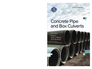
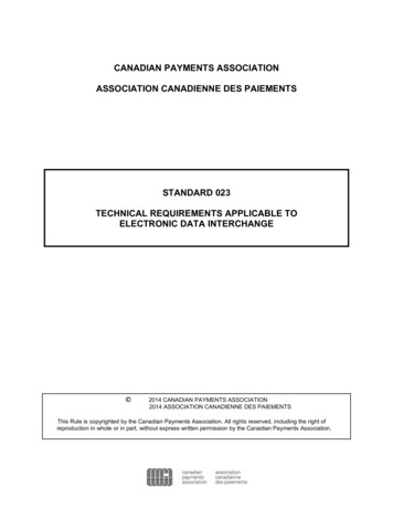
14ASTM Gasketed Joint Standards DevelopmentC361-1955C3611955 RReinforcedi fdCConcretet LLow-HeadH dPressure PipeC443 1959 Joints for Circular Concrete SewerC443-1959and Culvert Pipe, Using Rubber GasketsO-ring DetailProfile Detail
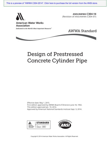
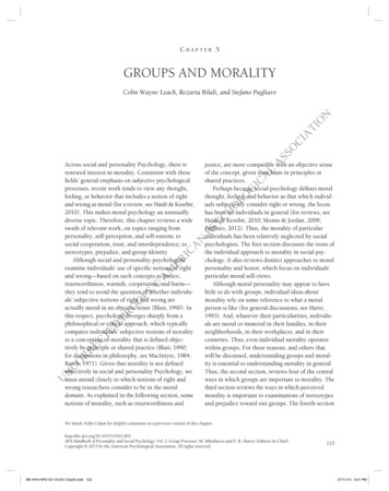
15ASTM Alternate Joint Standards DevelopmentC877-1977 External Sealing Bands forNoncircular Concrete Sewer, Storm Drain, andCulvert PipepC990-1991 Joints for Concrete Pipe, Manholes,and Precast Box Sections Using PreformedFlexible Joint SealantsC877 Type 1C877 Type 2C990
16CONCRETE PIPE JOINTSTANDARDS USE IN MUNICIPALPIPE APPLICATIONSLOW HEADLOW-HEADSANITARYSTORMCULVERTInfiltration limits:500 in.-gal/mi/dayNow tested to:200 in-gal/mi/day!
17CONCRETE PIPE JOINTSTANDARDS USE IN MUNICIPALPIPE APPLICATIONSLOW HEADLOW-HEADSANITARYSTORMCULVERTInfiltration limits:500 in.-gal/mi/dayNow tested to:200 in-gal/mi/day!
CONCRETE PIPE JOINTSTANDARDS USE INTRANSPORTATION PIPEAPPLICATIONSCO SCULVERTSTORM18
AASHTO PP63-09 - Standard RecommendedPractice for Pipe Joint Selection for HighwayCulvert and Storm DrainsJoint TypeSoil TightJoint SystemsJoint System StandardJoint System StandardAASHTOASTMMastic fillerAASHTO M198ASTM C990External Geotextile wrapAASHTO M288--ASTM C877Rubber GasketAASHTO M315ASTM C443Mastic fillerAASHTO M198ASTM C990-ASTM C877Rubber GasketAASHTO M315ASTM C443Rubber GasketAASHTO M315ASTM C443External Sealing BandsSilt TightExternal Sealing BandsWaterResistantSoil TightPlant Proof of DesignPlant Test CriteriaMaterial CertificationDimensional checksMaterial Certification & 3psi joint testDimensional Checks &Joint Test AASHTO M315(3 psi test in deflectedposition in lieu of 10 psi)Material Certification & 13 Dimensional Checks &psi joint testJoint Test AASHTO M315(13 psi test in straightalignment, and 10.8 psi indeflected position)Conduit joint which will not allow the transmission of backfill or native soil through the joint with design flow conditionsApplication: Culverts and storm sewers above water table, open channel flowSilt Tightgbackfill or native soil throughg the jointjwith designg flow conditionsConduit jjoint which will not allow the transmission of course or fine grainin the presence of external ground water or low internal head conditions.Application: Culverts and storm sewers presence of water table at or near top of pipe and fine grain insitu soil,Water ResistantConduit joint which will not allow the transmission of water in excess of a defined measurable rate through the joint with design flowconditions with or without the presence of external ground water or low internal head conditions. Must also meet/exceed "Soil and Silt TightJointsApplication: Storm sewers with presence of water table over top of pipe and fine grain insitu soil, possible low head flow conditionswww.concrete-pipe.org19
20A Complete Pipe StandardPipep Barrel Standard ((round,, elliptical,p, arch,, box)) Pipe Joint Standard (gasket, mastic, exterior wrap)Total Concrete Pipe Productwww.concrete-pipe.org
21ASTM Concrete Pipe Joint Standards 2010 ASTM C 361 08 Standard Specification for Reinforced Concrete Low-Head Pressure PipeASTM C 443 05 Standard Specification for Joints for Concrete Pipe and Manholes UsingRubber GasketsASTM C 1628 06 Standard Specification for Joints for Concrete Gravity Flow Sewer PipeUsing Rubber GasketsASASTMC 161677 09 Standard Specification for Joints for Concrete Box, Using Rubber GasketsASTM C 1619 05 Standard Specification for Elastomeric Seals for Joining ConcreteStructuresASTM C 505 05a Standard Specification for Irrigation Pipe with Rubber Gasket Joints
22ASTM Concrete Pipe Joint Standards 2010 ASTM C 877 08 Standard Specification for External Sealing Bands for Concrete Pipe,Manholes,, and Precast Box SectionsASTM C 990 09 Standard Specification for Joints for Concrete Pipe, Manholes and PrecastBox Sections Using Preformed Flexible Joint SealantsASTM C 1103 03 Standard Practice for Joint Acceptance Testing of Installed PrecastConcrete Pipe Sewer LinesASTM C 497 05 Standard Test methods for Concrete Pipe, Manhole Sections, or Tile
ASTM Concrete Pipe Rubber Gasketed Joint Standards 2010 ASTM C 361 08 Standard Specification for Reinforced Concrete Low-Head Pressure PipeASTM C 443 05 Standard Specification for Joints for Concrete Pipe and Manholes UsingRubber GasketsASTM C 1628 06 Standard Specification for Joints for Concrete Gravity Flow Sewer PipeUsing Rubber GasketsASASTMC 161677 09 Standard Specification for Joints for Concrete Box, Using Rubber GasketsASTM C 1619 05 Standard Specification for Elastomeric Seals for Joining ConcreteStructuresASTM C 505 05a Standard Specification for Irrigation Pipe with Rubber Gasket Joints
24ASTM C 361Standard Specification forR i fReinforceddCConcretet LLow-HeadH dPressure Pipe (1955)
25C361 Key Points Complete pipe standard, 6 Sack Mix (564 Lbs) Steel End Ring and Concrete Joints Gasket Deformation Limits (50%/15%) Deformation Calculations w/Full TolerancesApplied Hydrostatic Test to 120% of Design Pressuref 20 minutesfori t (d(designi 25’ -125’)125’) OffOff-CenterC t(Concrete to Concrete Contact or 150 lbs/inch)HydrostaticyTest Requiredq Alternate Designs & Gaskets Allowed (Par. 8.5) 100%% of Gsk. To Be Contained In Groove
26C361 Key Points
27ASTM C 443Standard Specification for Jointsf ConcreteforCt PipePi anddMManholes,h lUsing Rubber Gaskets (1959)
28Gasketed Joint Material Standards ASTM C443 Standard Specification for Joints for CircularConcrete Pipe and ManholesManholes, Using Rubber Gaskets
29Gasketed Joint Material Standards ASTM C443 Standard Specification for Joints for CircularConcrete Pipe and ManholesManholes, Using Rubber Gaskets
30C443 KKey PPointsi t Gasket Deformation Limits ((25%)%) CenteredPosition Bell taper 3.5 , up to 5 if proven by testing Reduced Gasket Tensile Properties fromC361 Alternate Designs Allowed (Par. 7.2) When Required by Owner, Hydrostatic Testto 13 psi Straight & 10 psi Deflected ½ “ allin the Centered Position
31ASTM C 1628Standard Specification for Jointsf ConcreteforCt GravityG it FlowFlSewerSPipe, Using Rubber Gaskets(2007)
32Designation: C 1628Standard Specification for Joints for ConcreteGravity Flow Sewer Pipe, Using RubberG k t 1Gaskets11. Scope1.1 This specification covers flexible leak resistant joints forconcrete gravity flow sewer pipe using rubber gaskets forsealing the joints, where measurable or definedinfiltration or exfiltration is a factor of the design.g Thespecification covers the design of joints and therequirements for rubber gaskets to be used therewith, forpipe conforming in all other respects to Specifications C14,C76, C655, C985, and C1417, provided that, if there isconflict in permissible variations in dimension, therequirements of this specification shall govern for joints.
33C1628 KKey PPointsi t
34C1628 KKey PPointsi t Rubber gasketed-include rational designparameters for o-ringo ring & profile & alternateconcepts include plant proof of design C443 hydrostatictest criteria, “deflected and off-centered”(concrete to concrete contact or 150 lbs/inch) include plant proof of design joint shear testcriteria (4000#/ft. dia.) includei l d ddesigni andd ttestingti submittalb itt l exampleslto insure uniformity include manufacturing QC/QA criteria toinsure the joint submitted is the joint shipped
35ASTM C 1677Standard Specification for Jointsf ConcreteforCt Box,BUsingU i RRubberbbGaskets (2009)
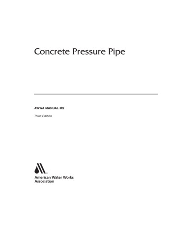
36Gasketed box section joints area reality in many areaswww.concrete-pipe.org
37C1677 KKey PPointsi t Gasket deformation limits ((25%)%) centeredposition including manufacturing tolerancesin calculations, not less that 15% in offcentered position Gasket properties similar to C443 Alternate designs allowed (Par(Par. 66.2)2) Hydrostatic proof of design test to 5 psistraight & 3 psi deflected for 10 minutes
38ASTM C 1619Standard Specification forEl tElastomerici SSealsl ffor JJoiningi iConcrete Structure (2005)
39C1619 KKey PPointsi t All ASTM C13 jjoint standards usinggggasketsto refer to this standard for gasket properties Gasket properties are defined in fiveclassifications A-E Gasket markings to meet this standard
SUGGESTED FUTURE ASTMJOINT STANDARDS GRIDDESCRIPTIONTYPICAL USEASTMLow-HeadLevees, dams, surchargedsewers, water irrigationC 361Measurableinfiltration &exfiltrationGravity flow sanitarysewers, hazard wastesewers etc,sewers,etcC 1628Water resistant, novisible leakageStorm sewer, culvertsunder high use roadsSoil resistantCulverts, storm sewersabove w.t.C 443C 877877*C 990*C 877C 99040
41INNOVATION:IndependentI dd t ConcreteCt PipePi CompaniesCifirst self unloading truck
42www.concrete-pipe.org
Wh t i ASTM?What is ASTM? American Society for Testing and Materials,established in 1898 ASTM International A voluntary consensus based organization which establishes matilt dd t ti t lterial standards or testing protocols American Section of the International Association for Testing Materials. The members grappled with two questions that were