Transcription
EMC VNX FamilyVNX5300 Hardware Information GuideP/N 300-013-308Rev 01June 25, 2012This guide describes one of five models available in the VNX Series, the EMC VNX5300 . This document provides an overview of the architecture, components, andfeatures of the VNX5300 platform. The specific aspects of the VNX5300 platform and itsmajor components include the front and rear connectors and LED indicators on the 3U, 15(3.5-inch) or 3U, 25 (2.5-inch) disk processor enclosure (DPE), the 1U standby powersupply (SPS), the 1U Control Station, the 2U Data Mover Enclosure (DME), and the 3U, 15(3.5-inch) or the 2U, 25 (2.5-inch) disk drive disk-array enclosure (DAE).This guide is available online at https://mydocs.emc.com/VNX/. Go to the About VNXsection, and then select Learn about VNX. Next, follow the steps in the wizard.Topics include: Product software and hardware release revisions . 2Revision history . 2Where to get help. 2How this document is organized . 3Related documentation. 3Overview. 4VNX5300 Block and File product description . 6System component description . 11I/O modules. 46Disk-array enclosure. 68Cabling . 85VNX5300 DAE cabling . 86
Product software and hardware release revisionsProduct software and hardware release revisionsAs part of an effort to improve its product lines, EMC periodically releases revisions of itssoftware and hardware. Therefore, some functions described in this document might notbe supported by all versions of the software or hardware currently in use. The productrelease notes provide the most up-to-date information on product features.Contact your EMC representative if a product does not function properly or does notfunction as described in this document.Note: This document was accurate at publication time. New versions of this documentmight be released on the EMC online support website. Check the EMC online supportwebsite to ensure that you are using the latest version of this document.Revision historyThe following table presents the revision history of this document:RevisionDateDescription01June 25, 2012First release of the VNX5300 HardwareInformation Guide with a document partnumber.Where to get helpEMC support, product, and licensing information can be obtained as follows:Product information — For documentation, release notes, software updates, orinformation about EMC products, licensing, and service, go to the EMC online supportwebsite (registration required) at:https://Support.EMC.comTechnical support — For technical support, go to EMC online support and select Support.On the Support page, you will see several options, including one to create a servicerequest. Note that to open a service request, you must have a valid support agreement.Contact your EMC sales representative for details about obtaining a valid supportagreement or with questions about your account.2EMC VNX5300 Hardware Information Guide
How this document is organizedHow this document is organizedThe major sections of this guide are listed in the following table.TitleDescription“Overview” on page 4Describes the software and hardware features of a typicalVNX5300 along with a front view example of the VNX5300.“VNX5300 Block and Fileproduct description” on page 6Describes and shows the front and rear views of a typicalVNX5300.“System componentdescription” on page 11Provides a description of the components that comprise aVNX5300. Along with a description, illustrations of eachcomponent are also shown.“DPE front views” on page 11Describes and illustrates the front of a DPE and the componentsthat comprise the front of the DPE.“DME front view” on page 18Describes and illustrates the front of the DME and thecomponents that comprise the front of the DME.“Standby power supply rearview” on page 20Describes and illustrates the 1U SPS used in the VNX5300.“DPE rear view” on page 25Describes and illustrates the rear of a DPE and the componentsthat comprise the rear of the DPE.“Control Station rear view” onpage 37Describes and illustrates the 1U SPS used in the VNX5300.“DME rear view” on page 42Describes and illustrates the rear of the DME and thecomponents that comprise the rear of the DME.“Disk-array enclosure” onpage 68Describes and illustrates the two types of DAEs available for theVNX5300.“VNX5300 DAE cabling” onpage 86Describes the types of DAE cabling available for the VNX5300platform. The cabling can be either interleaved or stackeddepending on your specific requirements.Related documentationEMC provides the ability to create step-by-step planning, installation, and maintenanceinstructions tailored to your environment. To create VNX customized documentation, goto: https://mydocs.emc.com/VNX/.To download a PDF copy of the desired publication, go to the following sections: For hardware-related books, go to the About VNX section, and then select Learn aboutVNX. Next, follow the steps in the wizard. For technical specifications, go to the About VNX section, and then select Viewtechnical specifications. Next, follow the steps in the wizard. For installation, adding, or replacing tasks, go to the VNX tasks section, and thenselect the appropriate heading. For example, to download a PDF copy of the VNX5300Block Installation Guide, go to Install VNX and follow the steps in the wizard.EMC VNX5300 Hardware Information Guide3
Overview For server-related tasks, go to the Server tasks for the VNX5300, VNX5500, VNX5700,and VNX7500 section, and then select the appropriate heading. For example, todownload a PDF copy of Adding or replacing hardware, go to Add or replace hardwareand follow the steps in the wizard.OverviewThe EMC VNX series implements a modular architecture that integrates hardwarecomponents for Block, File, and Object with concurrent support for native NAS, iSCSI1(Internet Small Computer System Interface), Fiber Channel, and Fibre Channel overEthernet (FCoE) protocols. The VNX series is based on Intel Xeon -based PCI Express 2.0processors and delivers File (NAS) functionality via two to eight Data Movers and Block(iSCSI, FCoE, and FC) storage via dual storage processors using a full 6-Gb/s SAS diskdrive topology. The VNX series is targeted at the entry-level to high-end/large-capacitystorage environments that require advanced features, flexibility and configurability. TheVNX series provides significant advancements in efficiency, simplicity, and performance.Benefits include: Support for File (CIFS and NFS), Block (FC, iSCSI & FCoE) and Object Simple conversions when starting with a VNX series Block only platform by simplyadding File services or starting with File only and adding Block services Support for both block and file auto-tiering with Fully Automated Storage Tiering(FAST) for Virtual Pools (VP - FAST VP) Unified replication with RecoverPoint support for both file and block data Updated unified management with Unisphere now delivering a more cohesiveunified user experienceThe VNX5300 is a mid-range/entry level storage platform. It offers Block, File, or UnifiedBlock and File services. These services consist of: Block-only—Includes a 3U disk processor enclosure (DPE), a 1U 1.2 KW standby powersupply (SPS), and 2U or 3U disk-array enclosures (DAEs) for holding hard disk drivesthat are integrated to facilitate Fibre Channel, Fibre Channel over Ethernet (FCoE), andiSCSI Block services to Windows and UNIX hosts. File-only—Adds the 2U Data Mover enclosure (DME) and 1U Control Station (CS) to the3U DPE, 1 U SPS, and 2U or 3U DAEs to facilitate File services to CIFS/NFS clients. Unified Block and File—Uses same hardware as the File-only configuration but addsFC, iSCSI, and FCoE I/O connectivity to provide Block services to host simultaneouslyso as to provide File services to clients.The VNX5300 platform supports two types of 3U DPEs and two types of DAEs. The 3U DPEssupported are a 15 drive 3.5-inch disk 3U enclosure (or DPE7) and a 25 drive 2.5-inch disk3U enclosure (or DPE8). The DAEs supported are a 15 drive 3.5-inch disk 3U enclosure (or1. iSCSI is a protocol for sending SCSI packets over TCP/IP networks.4EMC VNX5300 Hardware Information Guide
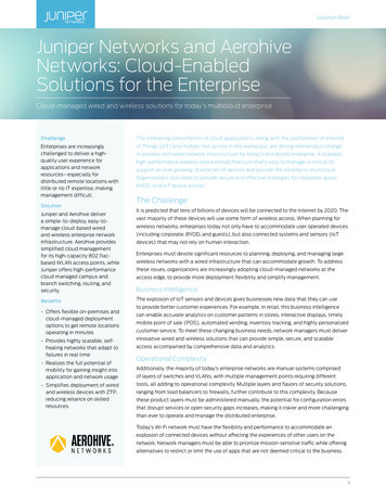
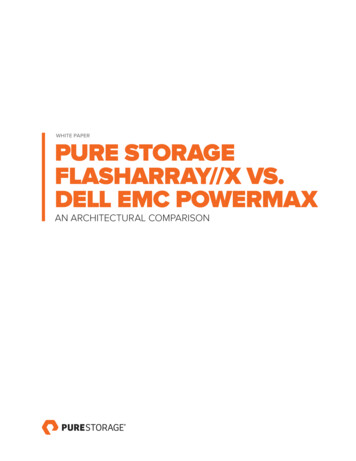
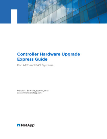
OverviewDAE6S) or a 25 drive 2.5-inch disk 2U enclosure (or DAE5S). Expansion of up to seven 3UDAEs (a maximum of 120 3.5-inch disk drives) or up to four 2U DAEs (a maximum of 1252.5-inch disk drives) is possible.As a mid-range/entry level storage platform offering Block, File, and Unified services, theVNX5300 platform (Figure 1) is one of the five models that make up the VNX series. For aquick look at the VNX5300 platform hardware features, see Table 1, “VNX5300 hardwarefeature quick reference,” on page 8.VNX-000565Figure 1 Example of a Block and File (Unified) VNX5300 platform with front bezelNote: A VNX5300 Block platform only includes an SPS and a DPE.EMC VNX5300 Hardware Information Guide5
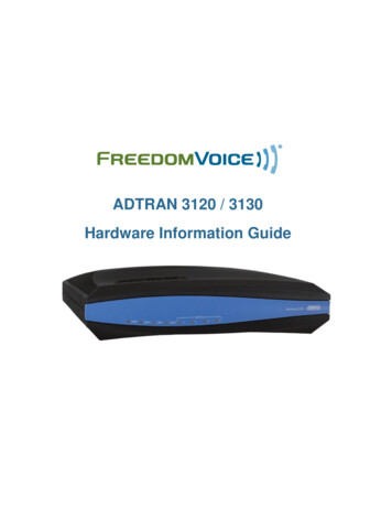
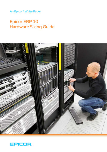
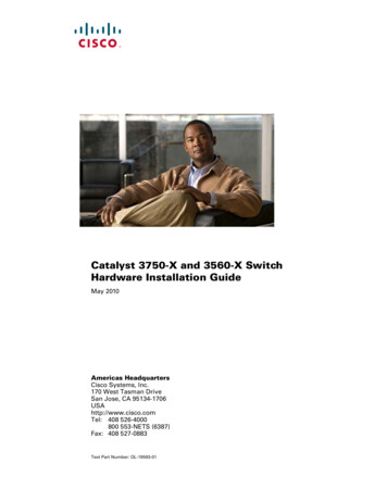
VNX5300 Block and File product descriptionVNX5300 Block and File product descriptionThis section shows an example of the front and rear views of a Block and File (Unified)VNX5300 platform.Note: A fully configured Unified VNX5300 platform includes up to seven 3U DAEs (amaximum of 120 3.5-inch disk drives) or up to four 2U DAEs (a maximum of 125 2.5-inchdisk drives).Front viewFigure 2 shows an example of the front view of a Block and File (Unified) VNX5300platform having a dual 1U SPS, a 3U, 15 (3.5-inch) disk drive 3U DPE, two 1U ControlStations (one optional), and one 2U Data Mover Enclosure with two Data Movers2. EachData Mover includes two power supply/cooling (fan) modules and one CPU module.ACACACACData MoverEnclosure 0DVDControl Station 1(optional)DVDControl Station 03U, 15 (3.5-inch)disk processorenclosure (DPE)SPSVNX-000562Figure 2 Example of a Block and File VNX5300 (Unified) platform with a 3U, 15 DPE (front view)Note: Figure 2 and Figure 3 on page 7 are examples of a Block and File (Unified) VNX5300platform (front and rear views). These figures are example of what a Block and File(Unified) VNX5300 platform looks like and are for illustrative purposes only.2. The term Data Mover is used throughout this guide. The term Data Mover is also referred to as ablade. These terms are interchangeable and mean the same thing.6EMC VNX5300 Hardware Information Guide
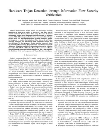
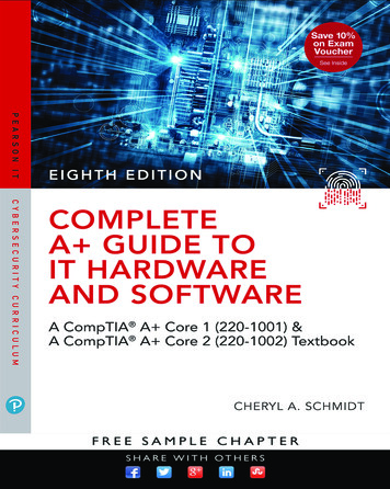
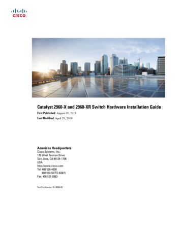
VNX5300 Block and File product descriptionRear viewCSB33Data MoverEnclosure 010221000112233310110010221001222233333Figure 3 shows an example of the rear view of a Block and File (Unified) VNX5300 platformhaving a dual 1U SPS, a 3U DPE with two storage processors (SP A and B), two (oneoptional) 1U Control Stations, and one 2U Data Mover Enclosure with two Data Movers.Each Data Mover includes two power supply/cooling (fan) modules and one CPU module.MGMTControl Station 1(optional)ACSBMGMTControl Station 0APART NUMBERREV A09APART NUMBERREV A09A3PART NUMBERREV A09A000B011112222333PART NUMBERREV A09A8Gb 6Gbfibre SAS2348Gb 6Gbfibre SAS1 X4526Gb SAS0 X4341 X45ADiskprocessorenclosure6Gb SAS0 X4SPSVNX-000563Figure 3 Example of a Block and File (Unified) VNX5300 platform (rear view)Hardware featuresContained in a 7 to 8U architecture, the Block and File (Unified) VNX5300 platform weighsapproximately 206.7 lb (93.76 kg) to 229.7 lb (104.19 kg) fully loaded3 depending on thetype of disk drives used in the 3U DPE. With the 2U DME having the deepest dimensionwithin the cabinet, the Block and File (Unified) VNX5300 measures 12.25 to 14 inches (7to 8U) high x 18.92 inches wide x 24.25 inches deep (31.11 to 35.56 cm x 48.05 cm x61.59 cm). Between the front and rear of the enclosure, a midplane distributes power andsignals to all the enclosure components. The CPU modules and the power supply modulesplug directly into the midplane connections.Note: The previously mentioned dimensions are approximate and do not include thecabinet enclosure.3. A fully loaded Block and File (Unified) VNX5300 platform (without any DAEs) includes two 1UControl Stations, a 3U DPE (with two SPs), one dual 1U SPS, and one 2U Data Mover Enclosurewith one to two Data Movers. In this fully loaded Block and File (Unified) VNX5300 platform, theDPE (with two SPs) can have either 15 (3.5-inch) drives or 25 (2.5-inch) drives. Separately, the 15(3.5-inch) drives weigh 34 lb (15.42 kg) and the 25 (2.5-inch) drives weigh 13.5 lb (6.13 kg),respectively.EMC VNX5300 Hardware Information Guide7
VNX5300 Block and File product descriptionFor physical, environmental, and power details, refer to the VNX5300 Storage SystemTechnical Specifications and Operating Limits document.Table 1 VNX5300 hardware feature quick referenceFileBlockMinimumformfactorMaximum# ofDrivedrivestypesConfig.I/O slotsper DataMover4U-7U12533.5 in.SAS,NL-SAS,Flash,and 2.5in. 10 KSASDataMoversSystemmemoryper DataMoverConfig.I/OslotsProtocols per SPBuilt-inI/O ports1 or 26 GBNFS,CIFS,MPFS1andpNFS24 FCportsplus 2BE3 SASports2SPsSystemmemoryper SP212 GBProtocolsFC, iSCSI,and FCoE1. MPFS Multi-Path File System2. pNFS parallel-NFS3. BE back endConfigured for AC-input power, the Block and File (Unified) VNX5300 platform includesthe following hardware features: One 3U DPE:IMPORTANTOn the rear of the 3U DPE, each storage processor includes a CPU module and a powersupply. Two latch handles on the bottom left and right provide each SP (SP A and SP B)with the means to secure the SP. The CPU and power supply modules can only be installedor removed after you remove the entire storage processor from the 3U DPE. On the front of the 3U DPE, three types of disk drives are supported in two diskdrive carrier types; 3U, 15 (3.5-inch) disk drive carrier (Figure 4 on page 13) or 3U,25 (2.5-inch) disk drive carrier (Figure 5 on page 14). The disk drives supported areSerial attached-SCSI (SAS), near-line SAS (NL-SAS), and Flash. On the rear of the 3U DPE, each (hot-swappable) storage processor (Figure 11 onpage 22) consists of:– A CPU module with an Intel Xeon 4-core 1.66-GHz processor with three DoubleData Rate Three (DDR3) synchronous dynamic RAM (SDRAM) slots supporting4-GB of SDRAM for a total of 12 GB per SP– Four integrated 8-Gb/s FC ports (labeled 2, 3, 4, and 5) supporting 2, 4, and8 Gb/s having front end auto-negotiation with support for manual override– Two integrated 6-Gb/s SAS x4 ports (labeled 6Gb SAS 0 x4 and 1 x4);supported speeds are 1.5, 3, and 6 Gb/s8EMC VNX5300 Hardware Information Guide
VNX5300 Block and File product description– Two PCI Gen 2 x4 I/O module slots supporting a combination of the followingUltraFlex I/O modules:a.) Two-port 10-Gb/s optical or active Twinax4 (w/iSCSI protocol); labeled10 GbE on the latch handleb.) Two-port 10-Gb/s RJ-45 Base-T iSCSI/IP; labeled 10 GbE Base-T on the latchhandleNote: The two-port 10-Gb/s RJ-45 Base-T/IP I/O module requires VNX OE for Fileversion 7.1 or later.c.) Four-port 1-Gb/s copper iSCSI; labeled 1 GbE iSCSI/TOE on the latch handled.) Four-port 8-Gb/s optical Fibre Channel (running at 2, 4, or 8-Gb/s); labeled8 GbE Fibre on the latch handlee.) Two-port 10-Gb/s optical or active Twinax3 Fibre Channel over Ethernet(FCoE); labeled 10 GbE/FCoE on the latch handleNote: The two-port 10-Gb/s optical or active Twinax FCoE I/O module requiresVNX OE for File version 7.0.35.3 or later.– One RS-232/EIA 232 serial (up to 115 K baud) service laptop (micro DB-9) port– One RS-232/EIA 232 serial management (micro DB-9) port– One 10/100/1000 LAN management (RJ-45) port– One 10/100/1000 LAN service (RJ-45) port– One power supply (hot-swappable) One 1U standby power supply (SPS) with a second (optional) SPS available One 2U DME with up to two Data Movers. Each Data Mover consists of: One CPU module consisting of one Intel Xeon 4-core 2.13-GHz processor Six DDR3 synchronous dynamic RAM (SDRAM) slots supporting up to 6 GB per CPUmodule One Fibre Channel (FC) I/O module with a:– Four-port 8 Gb/s optical (running at 2, 4, or 8 Gb/s); in slot 0; labeled8 GbE Fibre on the latch handle One to two of the following network I/O modules in any combination:– Two-port 10-Gb/s optical or active Twinax4; labeled 10 GbE v2 on the latchhandle– Two-port 10-Gb/s optical or Twinax4; labeled 10 GbE v3 on the latch handleNote: Version 3 of the two-port 10-Gb/s optical or active Twinax I/O modulerequires VNX OE File version 7.1 or later.– Four-port 1-Gb/s copper; labeled 1 GbE on the latch handle4. The two-port 10-Gb/s and FCoE I/O modules can also use active twinaxial (Twinax) cables. Twinaxis a type of cable similar to coax, but with two inner conductors instead of one. These cables willbe supplied in lieu of SFP transceiver modules when so ordered.EMC VNX5300 Hardware Information Guide9
VNX5300 Block and File product description– Two-port 1-Gb/s copper plus two-port 1-Gb/s optical; labeled 1 GbE on thelatch handle– Two-port 10-Gb/s RJ45 Base-T iSCSI/IP; labeled 10 GbE Base-T on the latchhandleNote: The two-port 10-Gb/s RJ-45 Base-T/IP I/O module requires VNX OE for Fileversion 7.1 or later. Two management modules per DME (or, one per Data Mover) Two power supply/cooling (fan) modules per CPU module One or two Control Stations. Each Control Station consists of the following features: Intel 2.0 GHz single core Celeron processor with 800-MHz front side bus (FSB) and512 KB cache 2 GB of RAM One 250-GB SATA hard drive Two rear-mounted USB ports and one front-mounted USB port Four 10BASE-T/100BASE-TX/1000BASE-T network interface (RJ-45) connectors(located on the rear panel) Two integrated serial ports, one for laptop/console redirection and one for theCallHome modem One DVD-ROM drive Expansion of up to seven 3U, 15 (3.5-inch) DAEs (a maximum of 120 drives) or up tofour 2U, 25 (2.5-inch) DAEs (a maximum of 125 drives)IMPORTANTWhen calculating the number of drives for your Block and File (Unified) VNX5300 platform,the 3U DPE is included in the total drive slot quantity of 120 to 125 drives. If the total driveslot quantity exceeds 120 or 125, you will not be able to add another DAE. Refer to“Disk-array enclosure” on page 68 for more information about the available expansionDAEs for the Block and File (Unified) VNX5300 platform.10 Any required cables including LAN cables, modem cables, and serial DB-9 cable. Mounting rails with hardware Front bezel with VNX5300 badgeEMC VNX5300 Hardware Information Guide
System component descriptionSystem component descriptionThis section describes the Block and File (Unified) VNX5300 platform components. Thesedetails include illustrations and descriptions of the front and rear connectors as well asthe LED indicators.Note: In the following sections, the illustrations and corresponding tables describe theseindividual components. These descriptions are for illustrative purposes only.VNX5300 front viewAs previously described, the Block and File (Unified) VNX5300 platform is made up of a3U DPE, a 1U SPS, one to two 1U Control Stations, and one 2U DME. The followingsections will describe the front (Figure 2 on page 6) view of the VNX5300 platformcomponents.D
The EMC VNX series implements a modular architecture that integrates hardware components for Block, File, and Object with concurrent support for native NAS, iSCSI1 (Internet Small Computer System Interface), Fiber C