Transcription
Catalyst 2960-X and 2960-XR Switch Hardware Installation GuideFirst Published: August 05, 2013Last Modified: April 29, 2014Americas HeadquartersCisco Systems, Inc.170 West Tasman DriveSan Jose, CA 95134-1706USAhttp://www.cisco.comTel: 408 526-4000800 553-NETS (6387)Fax: 408 527-0883Text Part Number: OL-28309-02
THE SPECIFICATIONS AND INFORMATION REGARDING THE PRODUCTS IN THIS MANUAL ARE SUBJECT TO CHANGE WITHOUT NOTICE. ALL STATEMENTS,INFORMATION, AND RECOMMENDATIONS IN THIS MANUAL ARE BELIEVED TO BE ACCURATE BUT ARE PRESENTED WITHOUT WARRANTY OF ANY KIND,EXPRESS OR IMPLIED. USERS MUST TAKE FULL RESPONSIBILITY FOR THEIR APPLICATION OF ANY PRODUCTS.THE SOFTWARE LICENSE AND LIMITED WARRANTY FOR THE ACCOMPANYING PRODUCT ARE SET FORTH IN THE INFORMATION PACKET THAT SHIPPED WITHTHE PRODUCT AND ARE INCORPORATED HEREIN BY THIS REFERENCE. IF YOU ARE UNABLE TO LOCATE THE SOFTWARE LICENSE OR LIMITED WARRANTY,CONTACT YOUR CISCO REPRESENTATIVE FOR A COPY.The following information is for FCC compliance of Class A devices: This equipment has been tested and found to comply with the limits for a Class A digital device, pursuant to part 15of the FCC rules. These limits are designed to provide reasonable protection against harmful interference when the equipment is operated in a commercial environment. This equipmentgenerates, uses, and can radiate radio-frequency energy and, if not installed and used in accordance with the instruction manual, may cause harmful interference to radio communications.Operation of this equipment in a residential area is likely to cause harmful interference, in which case users will be required to correct the interference at their own expense.The following information is for FCC compliance of Class B devices: This equipment has been tested and found to comply with the limits for a Class B digital device, pursuant to part 15of the FCC rules. These limits are designed to provide reasonable protection against harmful interference in a residential installation. This equipment generates, uses and can radiate radiofrequency energy and, if not installed and used in accordance with the instructions, may cause harmful interference to radio communications. However, there is no guarantee that interferencewill not occur in a particular installation. If the equipment causes interference to radio or television reception, which can be determined by turning the equipment off and on, users areencouraged to try to correct the interference by using one or more of the following measures: Reorient or relocate the receiving antenna. Increase the separation between the equipment and receiver. Connect the equipment into an outlet on a circuit different from that to which the receiver is connected. Consult the dealer or an experienced radio/TV technician for help.Modifications to this product not authorized by Cisco could void the FCC approval and negate your authority to operate the productThe Cisco implementation of TCP header compression is an adaptation of a program developed by the University of California, Berkeley (UCB) as part of UCB’s public domain versionof the UNIX operating system. All rights reserved. Copyright 1981, Regents of the University of California.NOTWITHSTANDING ANY OTHER WARRANTY HEREIN, ALL DOCUMENT FILES AND SOFTWARE OF THESE SUPPLIERS ARE PROVIDED "AS IS" WITH ALL FAULTS.CISCO AND THE ABOVE-NAMED SUPPLIERS DISCLAIM ALL WARRANTIES, EXPRESSED OR IMPLIED, INCLUDING, WITHOUT LIMITATION, THOSE OFMERCHANTABILITY, FITNESS FOR A PARTICULAR PURPOSE AND NONINFRINGEMENT OR ARISING FROM A COURSE OF DEALING, USAGE, OR TRADE PRACTICE.IN NO EVENT SHALL CISCO OR ITS SUPPLIERS BE LIABLE FOR ANY INDIRECT, SPECIAL, CONSEQUENTIAL, OR INCIDENTAL DAMAGES, INCLUDING, WITHOUTLIMITATION, LOST PROFITS OR LOSS OR DAMAGE TO DATA ARISING OUT OF THE USE OR INABILITY TO USE THIS MANUAL, EVEN IF CISCO OR ITS SUPPLIERSHAVE BEEN ADVISED OF THE POSSIBILITY OF SUCH DAMAGES.Any Internet Protocol (IP) addresses and phone numbers used in this document are not intended to be actual addresses and phone numbers. Any examples, command display output, networktopology diagrams, and other figures included in the document are shown for illustrative purposes only. Any use of actual IP addresses or phone numbers in illustrative content is unintentionaland coincidental.Cisco and the Cisco logo are trademarks or registered trademarks of Cisco and/or its affiliates in the U.S. and other countries. To view a list of Cisco trademarks, go to this URL: http://www.cisco.com/go/trademarks. Third-party trademarks mentioned are the property of their respective owners. The use of the word partner does not imply a partnershiprelationship between Cisco and any other company. (1110R) 2013,2014 Cisco Systems, Inc. All rights reserved.
CONTENTSPrefacePreface viiDocument Conventions viiRelated Documentation ixObtaining Documentation and Submitting a Service Request ixCHAPTER 1Product Overview 1Switch Models 1Front Panel 3PoE and PoE Ports 510/100/1000 Ports 5Management Ports 6USB Type A Port 7SFP and SFP Module Slots 7LEDs 7System LED 10RPS LED 10IRPS LED 11Master LED 11Port LEDs and Modes 11STACK LED 14Console LEDs 15Ethernet Management Port LED 15Rear Panel 15FlexStack-Plus Ports and LEDs 17RPS Connector 18Cisco RPS 2300 18AC Power Connector 19Catalyst 2960-X and 2960-XR Switch Hardware Installation GuideOL-28309-02iii
ContentsPower Supply Modules (Applies to the Catalyst 2960-XR Switches) 19Management Options 20Network Configurations 21CHAPTER 2Switch Installation 23Safety Warnings 23Box Contents 26Tools and Equipment 26Installation Guidelines 26Verifying Switch Operation 27Planning and Installing a Switch Stack (Optional) 28Stack Guidelines 28Installing the FlexStack-Plus Module 29Stack Cabling 31Stack Bandwidth and Partitioning Examples 32Power-On Sequence for Switch Stacks 33Installing the Switch 33Rack-Mounting 33Attaching the Rack-Mount Brackets for the Catalyst 2960-X Switches 35Attaching the Rack-Mount Brackets for the Catalyst 2960-XR Switches 36Mounting in a Rack 37Wall-Mounting 38Attaching the Brackets for Wall-Mounting 38Attaching the RPS Connector Cover 39Mounting on a Wall 40Installing the Switch on a Table or Shelf 41After Switch Installation 41Connecting the FlexStack Cables (Optional) 41Removing a FlexStack Cable 42Installing the Power Cord Retainer (Optional) 43Installing SFP and SFP Modules 45Installing an SFP or SFP Module 46Removing an SFP or SFP Module 47Connecting to SFP and SFP Modules 47Connecting to Fiber-Optic SFP and SFP Modules 48Catalyst 2960-X and 2960-XR Switch Hardware Installation GuideivOL-28309-02
ContentsConnecting to 1000BASE-T SFP 4910/100/1000 PoE Port Connections 5010/100/1000 Port Connections 51Auto-MDIX Connections 51Where to Go Next 52CHAPTER 3Power Supply Installation 53Power Supply Module Overview 53Installation Guidelines 56Installing or Replacing an AC Power Supply 57Finding the Serial Number 59CHAPTER 4Troubleshooting 61Diagnosing Problems 61Switch POST Results 61Switch LEDs 61Switch Connections 62Bad or Damaged Cable 62Ethernet and Fiber-Optic Cables 62Link Status 6210/100/1000 Port Connections 6310/100/1000 PoE Port Connections 63SFP and SFP Module 63Interface Settings 64Ping End Device 64Spanning Tree Loops 64Switch Performance 64Speed, Duplex, and Autonegotiation 64Autonegotiation and Network Interface Cards 64Cabling Distance 65Clearing the Switch IP Address and Configuration 65Finding the Serial Number 66Replacing a Failed Stack Member 67APPENDIX ATechnical Specifications 69Catalyst 2960-X and 2960-XR Switch Hardware Installation GuideOL-28309-02v
ContentsEnvironmental Specifications 69Specifications for the Catalyst 2960-X Switches 70Specifications for the Catalyst 2960-XR Switches 74APPENDIX BConnector and Cable Specifications 77Connector Specifications 7710/100/1000 Ports (Including PoE) 77SFP Module Connectors 78Cables and Adapters 78SFP Module Cables 78Cable Pinouts 80Console Port Adapter Pinouts 81APPENDIX CConfiguring the Switch with the CLI-Based Setup Program 83Accessing the CLI Through Express Setup 83Accessing the CLI Through the Console Port 83Connecting the RJ-45 Console Port 84Connecting the USB Console Port 85Installing the Cisco Microsoft Windows USB Device Driver 86Installing the Cisco Microsoft Windows XP USB Driver 86Installing the Cisco Microsoft Windows 2000 USB Driver 87Installing the Cisco Microsoft Windows Vista and Windows 7 USB Driver 87Uninstalling the Cisco Microsoft Windows USB Driver 87Uninstalling the Cisco Microsoft Windows XP and 2000 USB Driver 87Using the Setup.exe Program 88Using the Add or Remove Programs Utility 88Uninstalling the Cisco Microsoft Windows Vista and Windows 7 USB Driver 88Entering the Initial Configuration Information 89IP Settings 89Completing the Setup Program 89Catalyst 2960-X and 2960-XR Switch Hardware Installation GuideviOL-28309-02
Preface Document Conventions, page vii Related Documentation, page ix Obtaining Documentation and Submitting a Service Request, page ixDocument ConventionsThis document uses the following conventions:ConventionDescription or CtrlBoth the symbol and Ctrl represent the Control (Ctrl) key on a keyboard. Forexample, the key combination D or Ctrl-D means that you hold down the Controlkey while you press the D key. (Keys are indicated in capital letters but are notcase sensitive.)bold fontCommands and keywords and user-entered text appear in bold font.Italic fontDocument titles, new or emphasized terms, and arguments for which you supplyvalues are in italic font.CourierfontBold CourierTerminal sessions and information the system displays appear in courier font.fontBold Courierfont indicates text that the user must enter.[x]Elements in square brackets are optional.An ellipsis (three consecutive nonbolded periods without spaces) after a syntaxelement indicates that the element can be repeated. A vertical line, called a pipe, indicates a choice within a set of keywords orarguments.[x y]Optional alternative keywords are grouped in brackets and separated by verticalbars.Catalyst 2960-X and 2960-XR Switch Hardware Installation GuideOL-28309-02vii
PrefaceDocument ConventionsConventionDescription{x y}Required alternative keywords are grouped in braces and separated by verticalbars.[x {y z}]Nested set of square brackets or braces indicate optional or required choiceswithin optional or required elements. Braces and a vertical bar within squarebrackets indicate a required choice within an optional element.stringA nonquoted set of characters. Do not use quotation marks around the string orthe string will include the quotation marks. Nonprinting characters such as passwords are in angle brackets.[]Default responses to system prompts are in square brackets.!, #An exclamation point (!) or a pound sign (#) at the beginning of a line of codeindicates a comment line.Reader Alert ConventionsThis document may use the following conventions for reader alerts:NoteTipCautionTimesaverWarningMeans reader take note. Notes contain helpful suggestions or references to material not covered in themanual.Means the following information will help you solve a problem.Means reader be careful. In this situation, you might do something that could result in equipment damageor loss of data.Means the described action saves time. You can save time by performing the action described in theparagraph.Means reader be warned. In this situation, you might perform an action that could result in bodilyinjury.Catalyst 2960-X and 2960-XR Switch Hardware Installation GuideviiiOL-28309-02
PrefaceRelated DocumentationRelated DocumentationNoteBefore installing or upgrading the switch, refer to the release notes. Catalyst 2960-X Switch, located at http://www.cisco.com/go/cat2960x docs.Catalyst 2960-XR Switch, located at http://www.cisco.com/go/cat2960xr docs. Cisco SFP and SFP modules documentation, including compatibility matrixes, located ps5455/tsd products support series home.htmlObtaining Documentation and Submitting a Service RequestFor information on obtaining documentation, submitting a service request, and gathering additional information,see the monthly What's New in Cisco Product Documentation, which also lists all new and revised Ciscotechnical documentation, atsnew/whatsnew.htmlSubscribe to the What's New in Cisco Product Documentation as a Really Simple Syndication (RSS) feedand set content to be delivered directly to your desktop using a reader application. The RSS feeds are a freeservice and Cisco currently supports RSS version 2.0.Catalyst 2960-X and 2960-XR Switch Hardware Installation GuideOL-28309-02ix
PrefaceObtaining Documentation and Submitting a Service RequestCatalyst 2960-X and 2960-XR Switch Hardware Installation GuidexOL-28309-02
CHAPTER1Product OverviewThe Catalyst 2960-X and 2960-XR family of switches are Ethernet switches to which you can connect devicessuch as Cisco IP Phones, Cisco Wireless Access Points, workstations, and other network devices such asservers, routers, and other switches.Some models of the switches support stacking through the Cisco FlexStack-Plus technology. Unless otherwisenoted, the term switch refers to a standalone switch and to a switch stack.This chapter contains these topics: Switch Models, page 1 Front Panel, page 3 Rear Panel, page 15 Management Options, page 20 Network Configurations, page 21Switch ModelsTable 1: Catalyst 2960-X Switch Models and DescriptionsSwitch ModelSupportedSoftwareImageDescriptionCatalyst 2960X-48FPD-L1LAN Base48 10/100/1000 Power over Ethernet Plus (PoE ) ports (PoEbudget of 740 W) and 2 small form-factor pluggable (SFP) 2module slots.Catalyst 2960X-48LPD-L 1LAN Base48 10/100/1000 PoE ports (PoE budget of 370 W) and 2SFP module slots.Catalyst 2960X-24PD-L1LAN Base24 10/100/1000 PoE ports (PoE budget of 370 W) and 2SFP module
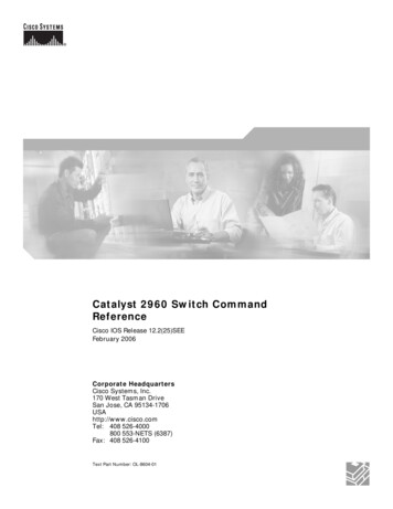
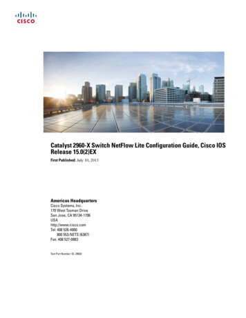
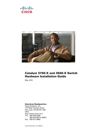
Figure 1: Catalyst 2960X-48FPD-L Front Panel 1 ModebuttonandswitchLEDs 5 SFPmoduleslots 2 USBmini-TypeB(console)port 6 10/100/1000PoE ports 3 USBTypeAport 7 RJ-45consoleport 4 USBTypeAport 8 Ethernetmanagementport ple.OtherCatalyst2960-XRswitcheshave similarcomponents. Figure 2: