Transcription
Design Manualfor SupermarketsSubsidiary of Acorn Engineering CompanyVACUUMPLUMBINGSYSTEMRev. Aug 8, 2007
CONTENTSSECTIONPAGEDesign Overview1.1Vacuum Center2.1Lifts3.1Horizontal Overhead Piping4.1Accumulators5.1Bracing Guidelines6.1Definitions ListAppendix AAccumulator SizingAppendix BOverhead Pipe SizingAppendix CBelow Grade AccumulatorAppendix DNote: The drawings and the information contained herein are and shall remain the property of AcornVac, Inc.This information and details may not be used or reproduced for any purposes other than stated in the documentsfor which they are intended. Unauthorized use in any form is strictly prohibited. All details and dimensions are subjectto change without notice. Contact AcornVac, Inc. or an authorized AcornVac representative for most current detail.
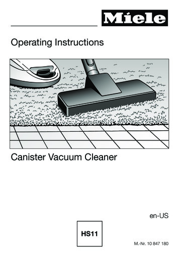
Design OverviewIntroductionThe AcornVac Vacuum Condensate and Grey WaterCollection System provides drainage of condensateand grey water through overhead vacuum piping inlieu of under floor gravity piping. By eliminating orreducing the need for floor drains and under floorpiping, a store has complete planning flexibility innew construction as well as flexibility to add orrelocate cases and fixtures with less disruption todaily store operation, and less loss of revenue duringremodeling.The system uses differential air pressure totransport waste and consists of four primarycomponents: Vacuum CenterThe Vacuum Center creates and maintainsvacuum pressure within the system anddischarges waste to sewer mains. Vacuum Piping NetworkThe vacuum piping network transports the wastefrom cases or fixtures to the Vacuum Center. Extraction Valve and ControllerThe Extraction Valve is designed to maintainintegrity between the negative pressures in thevacuum piping network and the surroundingatmosphere. The Controller activates theExtraction Valve in response to increased waterlevel in the Accumulator. AccumulatorThe Accumulator provides a point of collection forcondensate from cases and grey water fromsinks.OperationWaste is transported through the system fordischarge into sewer mains as follows: Vacuum is created and maintained by the vacuumpumps at the Vac Center. The vacuum pressure isheld within the system by the normally closedExtraction Valve. Condensate from cases and grey water fromsinks flow by gravity into an Accumulator. As the Accumulator fills, the Controller senses therising water level and activates the ExtractionValve allowing the waste to be moved from theAccumulator to the Vacuum Center collectiontanks through the vacuum piping network. When a Vacuum Center collection tank issufficiently full, the Vacuum Center control systemautomatically discharges the collected waste tothe sewer main.This guide is intended to provide a set of general guidelines for the designand installation of the AcornVac Vacuum Plumbing equipment.All installation should be made in compliance with local plumbing codes.AcornVac assumes no responsibility for void or superceded data.1.1
Design OverviewDetails regarding design and installation of AcornVac vacuum plumbing systems can be found in thefollowing sections: Section 2 - Vacuum CenterAccumulators are a temporary storagevessel for condensate or grey water. They aretypically installed in a concealed area close to thecase or fixture so that waste flows into theAccumulator by means of gravity.The Vacuum Center is typically located in the backof the store in a mechanical room, stock room, oron a mezzanine.The Accumulator includes an integral water levelsensor which is monitored by the Controller. Whenthe level in the Accumulator reaches a pre-setheight, the Controller activates the ExtractionValve allowing the waste to move into the vacuumpiping network. Section 3 - LiftsLifts connect Accumulators to the overhead pipingnetwork. They are typically located near existingsupport columns or within false columns.The Extraction Valve and Controller are integralcomponents of the Lift. The Extraction Valve islocated in a suitable position within the Lift and theController is typically located on top of the case orother accessible location. Section 5 - AccumulatorsThe Vacuum Center includes pumps, collectiontanks, electrical control panel, valves and fittingsnecessary to provide a fully integrated automaticsystem. Dual tanks and multiple pumps ensureredundancy.Vacuum Piping NetworkCondensate and grey water are transported fromthe Accumulator to the Vacuum Center fordischarge into sewer lines through the vacuumpiping network. The vacuum piping networkincludes Lifts and horizontal overhead piping. Section 4 - Horizontal Overhead PipingThe overhead horizontal piping network istypically located above a dropped ceiling or nearroof joists, and runs to the Vacuum Center.The vacuum piping network is typically providedand installed by a plumbing contractor inaccordance with guidelines as specified in thismanual (and in compliance with local buildingcodes.)1.2Section 6 - System Bracing Guidelines
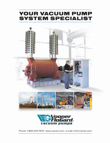
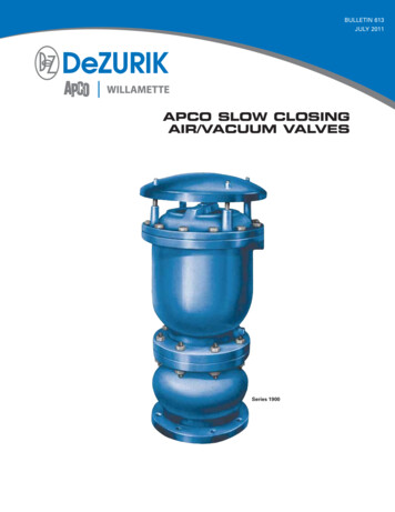
Design OverviewTYPICAL VACUUM CENTER1.3
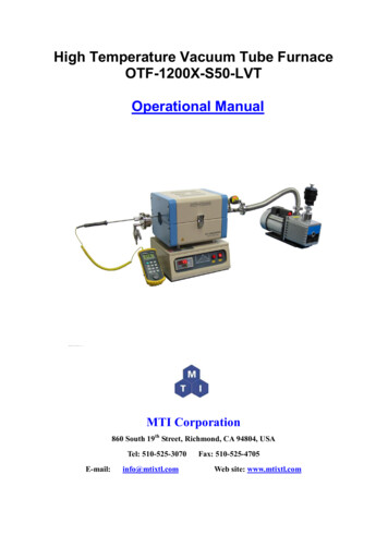
Design OverviewTYPICAL CASE AND COMPONENT ARRANGEMENT1.4
Vacuum CenterThe AcornVac Vacuum Center is a pre-packaged and factory tested system designed to serve thevacuum plumbing network. The Vacuum Center requires connections to the vacuum piping network,gravity drain, and electrical power source to make the system operational. All processes of the systemsuch as vacuum regulation, tank drainage, pump sequencing, pump alternation, alarm processing, andhistorical data collection are fully automated.VACUUM CENTER MODEL NUMBERS & DESCRIPTIONSAV - 30 S - 2 . 2 - LR - XXXCONFIGURATION OPTIONSPUMP TYPEH.P. PUMPNO. OF PUMPSSTAINLESS STEEL TANKTANK SIZE / U.S. GAL PER TANK2.1
Vacuum CenterVACUUM CENTER WEIGHTS, MEASURES,AND SERVICE AMP REQUIREMENTSPumpsSimplex SystemsFull Load Amperes 1&2Qty HP3 200-275V 2.10-LR21056.2433.24WeightsDryWet200 lbs375 lbs(91 kg)(170 kg)400 lbs750 lbs(182 kg)(340 kg)400 lbs750 lbs(182 kg)(340 kg)437 lbs871 lbs(199 kg)(170 kg)Overall DimensionsHW59 in20 in(1499 mm) (508 mm)83 in33 in(2108 mm) (838 mm)71 in31 inL23 in(584 mm)37 in(940 mm)43 in(1803 mm) (788 mm) (1092 mm)85 in24 in(2159 mm) (610 mm)39 in(991 mm)Duplex and Triplex SystemsNote 1:Note 2:Note 3:Note 4:Note 5:Note 6:Note 7:640 lbs 1300 lbs(291 kg)(590 kg)700 lbs 1365 lbs(317 kg)(635 kg)750 lbs 1450 lbs(341 kg)(658 kg)800 lbs 1667 lbs(363 kg)(756 kg)978 lbs 2000 lbs(444 kg)(908 kg)854 lbs 2221 lbs(388 kg)(1006 kg)1178 lbs 2206 lbs(535 kg)(1000 kg)950 lbs 2317 lbs(431 kg)(1051 kg)1125 lbs 2675 lbs(511 kg)(1214 kg)1250 lbs 2800 lbs(567 kg)(1270 kg)1525 lbs 3440 lbs(692 kg)(1561 kg)1350 lbs 3320 lbs(613 kg)(1506 kg)1620 lbs 3720 lbs(735 kg)(1688 kg)1870 lbs 4460 lbs(849 kg)(2023 kg)95 in34 in64 in(2413 mm) (864 mm) (1626 mm)84 in34 in60 in(2134 mm) (864 mm) (1524 mm)95 in34 in64 in(2413 mm) (864 mm) (1626 mm)85 in34 in60 in(2159 mm) (864 mm) (1524 mm)80 in37 in102 in(2032 mm) (940 mm) (2591 mm)90 in35 in(2286 mm) (889 mm)80 in37 in60 in(1524 mm)102 in(2032 mm) (940 mm) (2591 mm)90 in36 in60 in(2286 mm) (914 mm) (1524 mm)90 in35 in(2286 mm) (889 mm)90 in35 in(2286 mm) (889 mm)79 in44 in91 in(2311 mm)91 in(2311 mm)111 in(2006 mm) (1118 mm) (2819 mm)98 in39 in102 in(2489 mm) (991 mm) (2591 mm)108 in39 in102 in(2743 mm) (991 mm) (2591 mm)98 in44 in111 in(2489 mm) (1118 mm) (2819 mm)The Full Load Ampere data represents values that the Vac Center system will draw under normal operating conditions. Theelectrical service provided for the Vac Center must be sized in accordance with the latest edition of all National and LocalCode requirements.50Hz Voltages are 200-240 and 345-415 respectively.Horsepower ratings are nominal.10HP 60Hz System voltages are 220-275 and 380-480 respectively.Ambient temperature at Vac Center must not exceed 104o F (40o C).Contact factory for applications above 3300 Ft. (1000 M) elevation.This information is provided for reference only and is subject to change without notice.2.2
Vacuum CenterRECOMMENDED PIPING DETAILFOR MAKE-UP WATERLINE (BY OTHERS)2.3
Vacuum CenterVACUUM CENTER SIZING GUIDELINESLift points, water flow, and type of equipment determine the size of your AcornVac Vacuum Center. These guidelines areprovided as general information for estimating Vacuum Center size based on typical drainage requirements. Pleasecontact AcornVac or your local representative for additional information if the equipment or facility drainage requirementsare not covered in these guidelines.Sizing FactorsCalculate the total load requirement by adding the total point value for all equipment requiring vacuum drainage. Sometypes of equipment have higher volume drainage requirements and add a greater number of points. See the followingtable:Total LoadItemTotal QtyLoad FactorPoint Value *1. Refrigerated cases and refrigeration coilsDivide by 2.5 2. Hand sinksMultiply by 1.0 3. Misting systemsMultiply by 1.0 4. Floor drains, including trench drainsMultiply by 5 5. Prep sinksMultiply by 10 Total Lift Point Value *Note: Always round up to the next whole point when calculating total load point valuesCalculating SizeAdd the total value for each type of equipment to find the appropriate Vacuum Center size in the Selection Tablebelow.Example:Store requires vacuum drainage for the following equipment: 57 refrigerated and frozen food cases( 57 ) Divided by 2.5 22.8 232 misting systems(2)Multiply by 1.0 21 prep sink(1)Multiply by 10 102 floor drains(2)Multiply by 5 10Total Lift Point Value 45In this example, the total load point value is 45, which would recommend the use of anAcorn Vac Model AV-60S-2.3-LR-STK Vac CenterVAC CENTER SELECTION TABLEMaximum LoadPoint Capacity515203555556575100135MaximumMulti-Bay SinksVac Center ModelAV-20S-1.2-LR(BV) 1AV-30S-1.2-LR-STK 1 & 2AV-30S-1.3-LR-STK TKAV-60S-3.3-LR-STKAV-60S-2.5-LR-STK or AV-100S-2.5-LR 4AV-60S-3.5-LR-STK or AV 100S-3.5-LR 4AV-60S-2.10-LR-STK or AV-100S-2.10-LR 42.40000134577NOTES:1State and Local code may requireduplex pumps and tanks. If so,use AV-30S-2.2-LR-STK.2Same Load Point capacity appliesto AV-30S-1.2-LR-STK-MOB3Contact Factory for Sizingapproval on installations at orabove 3,300 Ft. (1000 m)4Use 100 Gallon Tank SizeSystems for applications thatcannot drain by gravity in 40seconds or less.
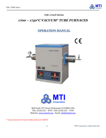
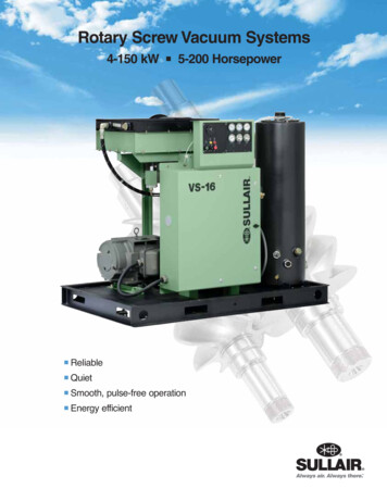
LiftsLifts connect Accumulators to overhead mains and branches leading to the Vacuum Center.TYPICAL LIFT INSTALLATIONUnder standard conditions, maximumallowable height is 25' (7.6 m). If higherLifts are required, please consult thefactory.Lifts require PVC Schedule 40 pressurerated 1-1/2" (40 mm) pipe or other vacuumrated piping.Where PVC is notacceptable, 1-1/2" copper, Type M orhigher piping is also acceptable.Lifts should be located near walls orcolumns for support and must be bracedper AcornVac requirements, (refer toSection 6 for details) using pipe clampsevery 6' (1.8 m) minimum and at anychange in direction.Lifts must be connected to theAccumulator with one 1-1/2" DWV longsweep fitting or two PVC Schedule 8045-degree elbows.The change in direction toward horizontalat the top of the lift must be made with one1-1/2" DWV long sweep fitting or two PVCSchedule 80 45-degree elbows.The connection from a Lift to thehorizontal main or branch must alwaysbe from above the centerline of the mainor branch. This connection should bemade via a wye fitting directed toward theVacuum Center. The wye fitting may berotated up to 45-degrees from vertical.3.1
ONSWhere obstructions in the path of a Lift occur, a single offset can be installed; however, it should not exceed12" (305 mm) horizontally and the change in direction should be made with two PVC Schedule 80 45-degreeelbow fittings or two DWV 1/8" bend fittings. Lifts may not include more than one offset and the Lift must bebraced with appropriate hangers within 12" (305 mm) of each change of direction. Refer to bracing details,Section 6.Note:Where store layout and design will not allow for a Lift from an island style refrigerated case directly to theoverhead piping network, gravity waste piping from the case may be installed in the same service trenchcontaining electrical and refrigeration piping to a point where a Lift is acceptable. The gravity plumbingshould terminate into an Accumulator.3.2
LiftsCONTROLLER AND EXTRACTION VALVE INSTALLATION DETAILNOTE:1234Flexible rubber tube must be attached to Extraction Valve Clip.Controller must be installed in an accessible location.Appropriate pipe bracing must be 12" (305 mm) away from Extraction Valve on both sides to allowcoupling to slide freely. See Section 6.1.Extraction Valve must be installed to allow for unobstructed movement.3.3
LiftsLIFT WITH EXTRACTION VALVE IN THE HORIZONTALLIFT WITH EXTRACTION VALVE IN THE VERTICAL3.4
LiftsTWO STAGE LIFT DETAILALTERNATIVE TWO STAGE LIFT ARRANGEMENT3.5
LiftsCOLLECTOR POCKET FOR TWO STAGE LIFT3.6
Horizontal Overhead PipingThe Horizontal Piping receives waste water from the Lifts and transports it to the Vacuum Center tanks. While thearrangement of the overhead piping network is unique for every installation, the following basic rules apply to thepiping design and installation:SLOPE & BRACINGThe horizontal piping must be installedwith a slope of 1/8" per 12" (1 mm per100 mm) toward the Vacuum Center,and supported or braced every 6' (1.8 m)minimum and against thrust load atevery change of direction. Seeadditional bracing details in Section 6.SLOPE MAKE
and installation of the AcornVac Vacuum Plumbing equipment. All installation should be made in compliance with local plumbing codes. AcornVac assumes no responsibility for void or superceded data. 1.1 Design Overview. SECTION PAGE Design Overview 1.1 Vacuum Center 2.1 Lifts 3.1 Horizontal Overhead Piping 4.1 Accumulators 5.1 Bracing Guidelines 6.1 Definitions List Appendix A