Transcription
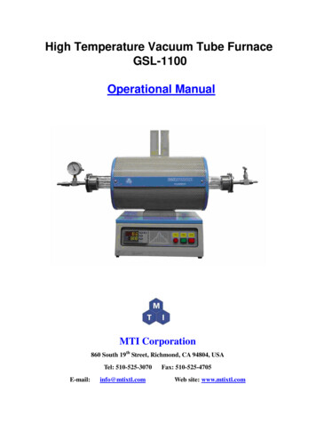
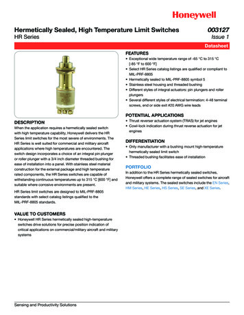
High Temperature Vacuum Tube FurnaceOTF-1200X-S50-LVTOperational ManualMTI Corporation860 South 19th Street, Richmond, CA 94804, USATel: 510-525-3070E-mail:info@mtixtl.comFax: 510-525-4705Web site: www.mtixtl.com
ContentIntroduction. 3Technical Specifications . 3Furnace Structure. 3Operating environment . 3Instrument features . 4Operation. 4Tube and flange installations . 4General Operation . 5Temperature Controller Instruction. 6Temperature Controller Setting. 7Temperature Segment Setting . 8Illustration of Temperature Segment Setting. 9Run the program. 10Hold the program. 10Stop the program . 10Temperature Controller Parameters . 10Introduction . 10Parameter Function.11Parameter Setting . 12Troubleshooting for typical Problems. 13Thank you for purchasing MTI’s products, please read this manual before using the furnace, MTI has no responsibilityfor any damage caused by customer’s misuse.Notice: The specification data may be different from the data on our website because we keep upgrading the products,if any confusion, please visit MTI’s website at www.mtixtl.com for the latest data.
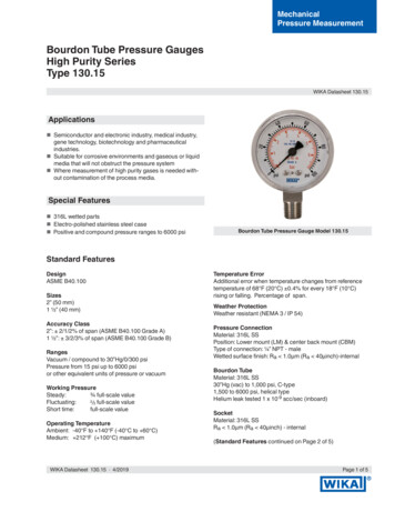
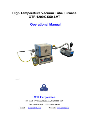
IntroductionOTF-1200X-S series high temperature vacuum tube furnace is a CE certified split tube furnace forheating samples up to 1200 oC. KF25 gas outlet and digital vacuum gauge on the right flange andbarb gas inlet on the left, allows the furnace to heat sample in vacuum or flowing gas. In addition,OMEGA 1/4’’ O.D thermal couple comes to the left flange, can be inserted inside the tube to exactlymeasure the sample’s temperature by the readout from the OMEGA calibrator. Precision temperaturecontroller can provide 30 segments heating and cooling steps with /- 1 C accuracy.Technical SpecificationsFurnace StructureOmega K typeInsert-ableThermo Coupleto CalibratorLeft FlangeQuartz TubeBellows Tube with KF25Fitting on Both EndsFurnace BodyDigital VacuumGaugeRightFlangeDual-Stage Filterwith KF25 FittingSealingKnobGas Inletwith ValveNeedle Valve withKF25 OutletMechanical PumpWorking r SwitchOperating environmentThe operating environment information in the following table may be helpful if you plan to safelyoperate the instrument: The construction request a dry, hard and flat surface;The instrument shall be kept indoor with nice ventilation and avoided direct sunlight;Operating temperature: 50 0C 350 0C;Relative humidity (noncondensing): 10% 85%;Dust-free.
WARNING: To reduce the possibility of heat-related injuries or of overheating the instrument,do not place the instrument too close to the side wall or obstruct the air vents. Keep the instrument atleast 1 meter in distance from the side wall.Instrument features Power:1200WOperating Voltage: 110V AC 10 Single Phase (16Amp air breaker required);Single Phase, 50/60 HzOverall Dimensions D x H x W (mm): 340 x 300 x 400;304 stainless steel chamber;Maximum Temperature: 1200 0C ( 1 hour)Continues Working Temperature: 1100 0CTemperature accuracy: /- 1 0C;Suggested Normal Heating Rate: 10 0C /minMax. Heating Rate: 30 0C /min;Constant Temperature zone: 4" (100mm) ( /-1 C) @ 1000 C;Temperature control: 30 segments programmable digital controller with PID function andoverheated and overloaded protection;Vacuum Level: 10-2 torr (by mechanical pump);Quartz Tubes size (inch): 1. 50mm O.D x 43mm I.D x 450mm L (OTF-1200X-S50)2. 25mm O.D x 20mm I.D x 450mm L (OTF-1200X-S25)Heating Elements: Fe-Cr-Al Alloy doped by Mo;Net weight (kg): 18;Warranty: One Year limited, not included quartz tube.OperationTube and flange installationsOnce you received MTI furnace, please follow these steps to set up the furnace. Open the box; check out if the instrument and the accessories are well kept during theshipping.The instrument shall be kept indoor with nice ventilation;Slightly insert the quartz tube from one side;Insert the foam block and seal the tube at both ends with flanges.
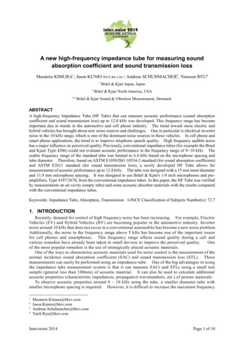
To well install the flange with thermo couple feed through, please be advised that:1. You must put the sealing o-ring in between the feed through and the sealing knob.2. The foam block with groove on it is dedicated to the 1/4’’ O.D. thermal couple.Foam with GrooveSealing KnobSealing O-ring (Black or White in Color)You may need “Pipe Twist” to tighten the Sealing Knob finally.Please refer to the picture below to properly install KF25 fitting:
General Operation Place the test sample inside the tube, slightly insert the foam block and then seal both endof the tube with flanges. If you are going to set up the Vacuum/Gas Flow system with the furnace, please properlyset the vacuum level / flowing rate when you need to purge and charge the inert gas into thetube. It is highly recommended to apply vacuum grease on the flange joint, please x for more information.You must pre-heat the two Alumina Blocks to 800-1000C to drive away the moisture insidethem (because the block is porous) , otherwise, you can not get to 1E-2 torr by mechanicalpump, for instance, the engineer in MTI reached only 1.45 torr before the preheating and1.8E-2 torr after it.Quick Test program is perfect to preheat the alumina block. Properly connect to the power supply and make sure it is well grounded; Power on the instrument by pressing “On/Off” button and you will see the control panelstart to blink. Please refer to the following part “Temperature Controller Instruction” for how to set thetemperature curve.NOTE:Once you finish the set up, we strongly recommend our customer FIRSTLY reading thehandbook and then following the instructions of attached “QUICK TEST” inside the package toperform a quick test to check the heating condition of the furnace.CAUTION: To reduce the risk of electric shock or damage to your instrument during yourquick test, observe these practices: The outer plate of the instrument must be grounded properly, for safety of operation; The instrument shall be kept indoor with nice ventilation; To reduce potential safety issues, do not place flammable and explosive materials around theinstrument; No explosion-proof, do not put any flammable and explosive materials into the chamber.Temperature Controller InstructionMTI provide two kinds of temperature controller with same function:
Here, we will introduce the left one:Increase button(END)Furnace Temp.(PV)Decrease button(RUN/PE)FunctionIndicatingProgram setting/LeftShift/Auto-tune(AT/PROTA/M)Setting Temp.(SV)Parameter setting/Start the Program,view the time running (SET PAR)Temperature Controller SettingStartup stateWhen start the device, the meter type and program version will display for a few seconds, and thenenter the normal state. Blinking “End” indicates the program is in stop state.Meter type & Program versionNormal stateDisplaying switcha. In the “normal state” or “program running state”, press “SET” key for 1 secondto switch to “executing program segment” (Set executing segment or displaythe ongoing temperature segment).b. Press “SET” key again for 1 second to switch to “running time state” (Display thetotal running time PV xxxx min. and the elapsed time SV xxxx min.)c. Press “SET” key again for 1 second to back to “normal state”.
Temperature Segment SettingLTDE programmable smart instrumentation auto-controller allows you to set the temperature profileup to 30 segments. To process this function, follow these steps: Power on the furnace, blinking “End” on the SV window indicates the Normal State;Press “ ” once to display “C01” on PV window; Set initial temperature to 0 oC by using Keystrokes :“ ”, “ ” or “ ”;Press “Set” to display “t01” on PV window; Set heat-up time (Usually beyond 30 minutes for this segment in case of temperatureovershooting) from initial temperature to target temperature by using Keystrokes :“ ”, “ ” or“ ”;Press “Set” to display “C02” on PV window; Set the actual working temperature for the secondsegment by using Keystrokes :“ ”, “ ” or “ ”; Press “Set” to display “t02” on PV window; Set heat-up time from initial temperature to targettemperature by using Keystrokes :“ ”, “ ” or “ ”; Press “Set” to display “C03” on PV window, Set the actual working temperature for the thirdsegment;Press “Set” to display “t03” on PV window; Set heat-up time from initial temperature to targettemperature;
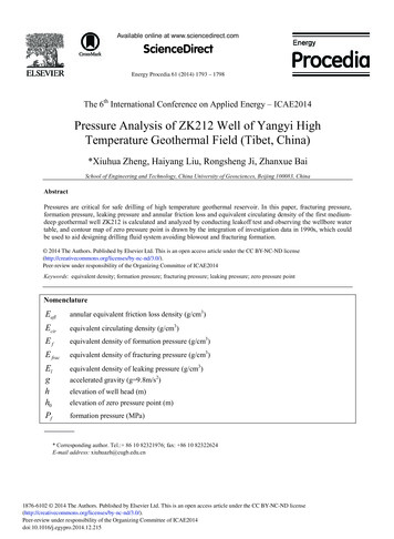
Press “Set” to display “C04” on PV window, Set the actual working temperature for the fourthsegment;Press “Set” to display “t04” on PV window, Use Keystrokes :“ ”, “ ” or “ ” to set durationfor owingsegments(C05&t05 C06&t06 C07&t07 ) for temperature and time setting;Press “Set” to display “Cxx” on PV window (xx could be any values among 01 30);Press“ ”, “ ” or “ ” to set “-121” in the last segment in order to shut down the furnace;Illustration of Temperature Segment SettingSetting Example:According to figure I above, all segments was recorded in the following:Prompt Input DataDescriptionC010Initial TemperatureT0145Heat-up time 45 minutes from 0-450 oC in the first segmentC02450Target temperature of the first heat-up stageT0220Heat-up time 20 minutes from 450-500 oC in the second segmentC03500Target temperature of the second heat-up stage
T0340Keep 40 minutes at 500 oCC04500Constant temperature of the third stageT0430Heat-up time 30 minutes from 500-1000oC in the fourth segmentC051000Target temperature of the fourth heat-up stageT0525Keep 25 minutes at 1000oCC061000Constant temperature of the fourth stageT0620Cooling time 20 minutes from 1000 to 800oCC07800Target temperature of the fifth heat-up stageT0725Keep 25 minutes at 800oCC08800Constant temperature of the sixth stageT08-121Program end, Out-put power off. Furnace cooling down naturally.(t08 -121 is an order to stop running)Run the program When temperature program set up ready, wait until “End” shows on SV window again, thenpress “ ”and hold for two seconds to display “Run” on SV window; Furnace will run automatically segment by segment according to the program setting; PV window displays increasing temperature at this moment;Hold the program If you need to hold the furnace at certain temperature when the program is running, press “ ”for 2 sec to hold the program and again press it to continue.Stop the program You can stop the program either from running or hold state by pressing “ ” for 2 seconds.Attention: When finish all the segments you need, please end the last segment with -121; It is not suggested to modify any parameters during the execution if he or she is not familiarwith the furnace operation. If there is a must, please first stop the program.Temperature Controller nce Integralfunction1-9999Unit/NoticeDefaultValue
ProLtCrtContPlocEnhance ProportionfunctionLimit time factorControl period andauto-tune determiningControl type settingLock the setting1-99991-2000Second1 83,2031008 to unlock0Parameter FunctionInt (Integral effect)Int is related to the system sustainment, take temperature for example, the larger, the more stable thesystem is. Like integral time of PID calibration, this parameter is mainly in charge of the integralwork during the adjustment process, for instance, the smaller the Int is set, the stronger the systemintegral effect is, vice versa. When Int 0, the system will cancel integral and intelligent adjustment.Pro (Proportion effect)Pro is used for adjusting proportion and differential effect. The larger Pro is, the smaller proportioneffect is, which means both adjustment and differential effect are enhanced to get sensitive ability tothe temperature change, vise versa.Lt (Delay time coefficient)Lt is used to determine tradeoff of the proportion and differential. When it is small, proportion isstrong and differential is weak, vise versa. If Lt is no more than the twice of Crt (will mention below),differential effect is off.Note: The three parameters discussed above should be adjusted after “auto-tune”.Crt (Period control and auto-tune determination)Crt is applied for adjusting the calculation cycle (unit is second), which makes critical impact on thesystem adjustment and of course,
High Temperature Vacuum Tube Furnace OTF-1200X-S50-LVT. Operational Manual. MTI Corporation. 860 South 19thStreet, Richmond, CA 94804, USA Tel: 510-525-3070 Fax: 510-525-4705 E-mail: info@mtixtl.com Web site: www.mtixtl.com. Content. Introduction.