Transcription
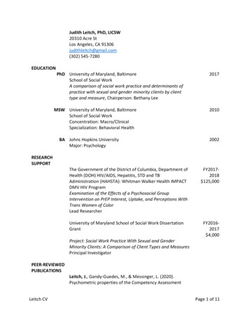
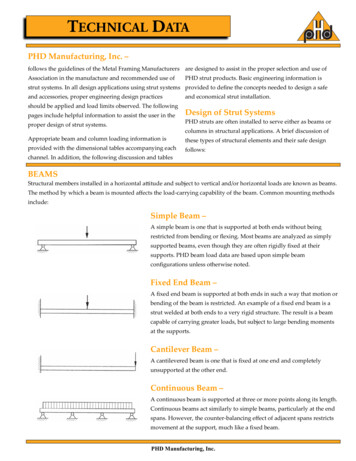
PHD Manufacturing, Inc. –follows the guidelines of the Metal Framing Manufacturers are designed to assist in the proper selection and use ofAssociation in the manufacture and recommended use ofPHD strut products. Basic engineering information isstrut systems. In all design applications using strut systems provided to define the concepts needed to design a safeand accessories, proper engineering design practicesshould be applied and load limits observed. The followingpages include helpful information to assist the user in theand economical strut installation.Design of Strut SystemsPHD struts are often installed to serve either as beams orproper design of strut systems.columns in structural applications. A brief discussion ofAppropriate beam and column loading information isthese types of structural elements and their safe designprovided with the dimensional tables accompanying eachfollows:channel. In addition, the following discussion and tablesBEAMSStructural members installed in a horizontal attitude and subject to vertical and/or horizontal loads are known as beams.The method by which a beam is mounted affects the load-carrying capability of the beam. Common mounting methodsinclude:Simple Beam –A simple beam is one that is supported at both ends without beingrestricted from bending or flexing. Most beams are analyzed as simplysupported beams, even though they are often rigidly fixed at theirsupports. PHD beam load data are based upon simple beamconfigurations unless otherwise noted.Fixed End Beam –A fixed end beam is supported at both ends in such a way that motion orbending of the beam is restricted. An example of a fixed end beam is astrut welded at both ends to a very rigid structure. The result is a beamcapable of carrying greater loads, but subject to large bending momentsat the supports.Cantilever Beam –A cantilevered beam is one that is fixed at one end and completelyunsupported at the other end.Continuous Beam –A continuous beam is supported at three or more points along its length.Continuous beams act similarly to simple beams, particularly at the endspans. However, the counter-balancing effect of adjacent spans restrictsmovement at the support, much like a fixed beam.PHD Manufacturing, Inc.
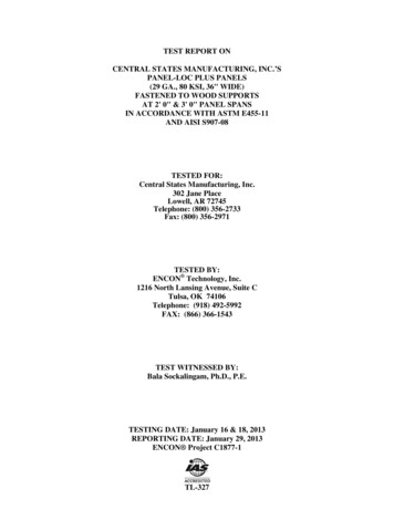
TYPES OF BEAMLOADINGBeam Loading –Beams are loaded in several ways, as shown below.Concentrated Load –Also known as a point load, this type of load is applied at one point along the span of the beam. See Figure1. A beam may have multiple concentrated loads along its span.Uniform Load –This is a load spread evenly over a length of the beam’s span. See Figure 2. It may cover the entire span oronly a portion.Combined Load –Concentrated loads and uniform loads may be carried simultaneously by a beam, arranged in anycombination.BEAMDEFLECTIONDeflection –Deflection is the amount of displacement, or sag, experienced by a load-carrying beam. All loaded beamswill deflect to a greater or lesser degree, depending upon: The size and placement of loads The beam material The manner of supporting the beam The stiffness of the beamPHD provides deflection values for beams of various spans in the tables ac companying each channel shape.When determining the deflection of a strut, the rule of thumb observed by the industry is that a deflection of1/240th of the beam’s span is acceptable.The following table of beam formulas contains factors to be applied when ana lyzing a strut/beam in variousconfigurations. These factors account for the difference in deflection that will be experienced by beamsmounted in various configurations and subject to various types of loads.Also included in the tables of channel information are values for the Moment of Inertia (I) and SectionModulus (S) of the channel. These values are given for both the X-X and Y-Y axis of the channel. They aremeasures of the stiffness of the beam’s cross-sectional shape, and are used to calculate deflection. Deflec tiondecreases as I and S increase. The Modulus of Elasticity (E), listed below I and S, is a measure of the beammaterial’s resistance to bending. Again, as E increases, deflection decreases.SAFETY FACTORSafety Factor –The design loads given for strut beam loads are based on a simple beam condition using allowable stress of25,000 psi. This allowable stress results in a safety factor of 1.68. This is based upon a virgin steel minimumyield strength of 33,000 psi cold worked during rolling to an average yield stress of 42,000 psi.Aluminum typically has an elastic modulus which is 1/3 that of steel even though they may have identicalstrength. As a result, the deflection of aluminum channel will be three times that of steel channel underequal loading. In areas where structures will be subject to general viewing, deflection can produce adispleasing effect. To the untrained eye, a sagging channel may appear to be a result of poor design orexcessive loading. This is not usually the case. Many properly designed channel installations will show anoticeable deflection at their designed loads. In areas where cosmetics are not important, deflection shouldnot be a factor. Designing an entire installation based on minimal deflection could result in an over designedstructure. This translates into increased material and installation cost. Where cosmetics are important, it maybe necessary to limit the deflection to an aesthetically pleasing amount. This “acceptable deflection” amountis typically given as a fraction of the span. 1/240 span deflection is typically the limit where the amount ofdeflection appears negligible. For example, a beam span of 240” would be allowed 1” (240/240) of deflection atthe mid point. A 120” span would only be allowed 1/2” (120/240) of deflection. The maximum load for thechannel must be limited in order to remain under these deflection requirements. The allowable loadresulting in 1/240 span deflection is posted in the beam load chart for each channel size.For even more stringent deflection requirements, an allowable load is listed in the beam load charts whichresults in 1/360 span deflection. This amount of deflection is sometimes used for beams in finished ceilingsthat are to be plastered.PHD Manufacturing, Inc.
Bending Moments & Stresses –When loads are placed on a beam, the effect is to flex the beam across its unsupported span. The measure ofthis effect is called the bending moment. Formulas for bending moments created by various load and beamsupport combinations are given in the following tables.When the bending moment of a loaded beam is divided by the Section Modulus of the beam, the resultingBENDINGMOMENTS& STRESSESvalue is called bending stress. It is this bending stress that is most commonly evaluated to determine whethera beam is strong enough for the loads it must support.The maximum bending stress prescribed by structural codes is 25,000 psi (172.37 mPa), and this is the stressupon which PHD load figures are based.Again, the method of supporting a beam affects the maximum bending moment of the beam. The followingtable gives modifying factors based upon types of beam supports. Users of PHD struts should take care toapply the proper load factor for the specific beam support configuration in order to determine the propermaximum load that the strut will safely support.Twisting & Lateral Bracing –For long spans and when loads are apt to cause torsion on the beam, it is a good practice to brace the beam toprevent twisting or lateral bending. PHD offers various types of braces for this purpose.Loading of strut on long spans can cause torsional stress, resulting in the tendency of the strut to twist or bendlaterally. This phenomenon reduces the allowable beam loads as shown in the beam loading charts. It isTWISTING &LATERALBRACINGrecommended that long spans be supported in a manner to prevent twisting (fixed ends), and that the channelhave adequate lateral bracing. Many typical strut applications provide this support and bracing inherently.Piping, tubing, cable trays, or conduits mounted to the strut with straps and clamps prevent twisting or lateralmovement. If no such lateral support exists, contact the factory for loading recommendations.Spot Welding –WELDINGResistance welding of back to back strut channel is accomplished byway of an AC powered press type spot welder. This equipmentproduces a series of spot welds from 2" (50.8) to 4" (101.6) apartcontinuously down the length of the channel. Consistency is maintainedby the use of a highly sophisticated constant current weld control. Thisprocessor is capable of maintaining weld sequence, duration andcurrent control along with other variables. Any deviations in theprogrammed parameters will issue forth an alarm or shut down fault,which is then investigated. Weld quality is tested every 300-350 weldsthrough the use of a destructive test method.Through the use of modern technology, destructive and non-destructivetesting, the quality of strut can be maintained. Spot weld strut isfabricated in accordance with the R.W.M.A. guidelines for resistancewelding.MIG Welding –MIG welded, more properly called gas metal arc welded (GMAW)combination channels and fittings, are produced when physicaldimensions or certain combinations require a weld process other thanautomatic spot welding. The same quality control requirements areimposed on MIG welded and spot-welded products.3/16” (4.76) FilletUnless otherwise specified, all dimensions on drawings and in charts are in inches and dimensions shown in parentheses are in millimeters.PHD Manufacturing, Inc.
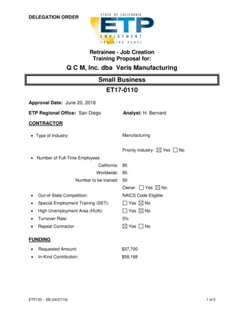
Columns –COLUMNSStructural members installed in a vertical attitude and subject to vertical loads are known ascolumns. The loads on a column have the effect of compressing the column and attempting todeflect the column laterally. As with beams, the method by which a column is mounted affectsthe load-carrying capability of the column. The effect of each method is quantified by the value“K”, given for each support condition shown below.Loads on a column may be concentric (directly in line with the column’s vertical axis) oreccentric (offset horizontally from the vertical axis). PHD provides allowable column loads forconcentric loading conditions. In addition, the tables accompanying the channels contain a valuecalled the “radius of gyration”. This value can be used by a qualified structural engineer toanalyze the effect of eccentric loads on strut columns.Common mounting methods for columns include:Fixed Top, Fixed Bottom –Both the top and bottom of the column are rigidly mounted in such a way that rotation anddisplacement are prevented. The value of “K” for this configuration is .65. See Figure 1.Pinned Top, Pinned Bottom –Both the top and bottom of the column are mounted in such a way that rotation is permitted butdisplacement is prevented. The value of “K” for this configuration is 1.0. See Figure 2.Pinned Top, Fixed Bottom –The top of the column is pinned to allow rotation, and the bottom of the column is rigidlymounted in such a way that rotation and displacement are prevented. This is a commonmethod. And is the “standard” for which PHD allowable column loads are listed. The value of“K” for this configuration is .80.See Figure 3.Free Top, Fixed Bottom –The bottom of the column is rigidly mounted. The top of the column is free to move laterally,but is restrained to prevent rotation. The value of “K” for this configuration is 1.2. See Figure 4.As stated above, allowable column loads published in this catalog are based on the “PinnedTop, Fixed Bottom” mounting configuration, which has a “K” factor of .80. For any of the othermounting configurations, a qualified design professional can use the “K” values given tocalculate the allowable column load.Bolt Torque –BOLT TORQUEBolt TorqueBolt Sizeft-lbsRec.Torque N-m1/45316111950(8)/16/8/25/81003/4Bolt torque values are given to ensure the proper connection between PHD Metal Framingcomponents. It is important to understand that there is a direct, but not necessarilyconsistent, relationship between bolt torque and tension in the bolt. Too much tension in thebolt can cause it to break or crush the component parts. Too little tension in the bolt canprevent the connection from developing its full load capacity. The torque values given havebeen developed over many years of experience and testing.125(15) (26) (68) (136) (170)These are based on using a properly calibrated torque wrench with a clean dry (nonlubricated) PHD fitting, bolt and nut. A lubricated bolt or nut can cause extremely hightension in the connection and may lead to bolt failure. It must be noted that the accuracy ofcommercial torque wrenches varies widely and it is the responsibility of the installer toensure that proper bolt torque has been achieved.Unless otherwise specified, all dimensions on drawings and in charts are in inches and dimensions shown in parentheses are in millimeters.PHD Manufacturing, Inc.
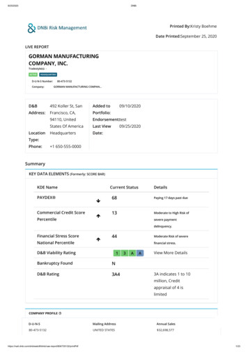
BEAM DIAGRAMS AND COMMON FORMULASSimply Supported BeamsFixed End BeamsCantilever BeamsBeams with one end Fixed, one end Simply SupportedPHD Manufacturing, Inc.
Beam Load and Deflection Conversion Factors –The allowable beam loads listed for various spans of each channel assume that the beam is a simply supported, singlespan beam. Although this is the most common condition, it is not always true. For other support conditions, multiplythe listed allowable load by the factors in this table to obtain the proper load for the given mounting type.LoadFactorDeflectionFactor1) Simply Supported Beam,Uniform Load1.001.002) Simply Supported Beam,Concentrated Load at Mid-span.50.803) Simply Supported Beam,Two equal Concentrated Loads at 1/4 Points1.001.104) Fixed End Beam,Uniform Load1.50.305) Fixed End Beam,Concentrated Load at Mid-span1.00.406) Cantilever Beam,Uniform Load.252.407) Cantilever Beam,Concentrated Load at End.123.208) Continuous Beam, Two Equal Spans,Uniform Load Both Spans1.00.429) Continuous Beam, Two Equal Spans,Uniform Load on One Spans1.30.921
When determining the deflection of a strut, the rule of thumb observed by the industry is that a deflection of 1/240th of the beam’s span is acceptable. The following table of beam formulas contains factors to be applied when ana lyzing a strut/beam in various configurations. These factors account for the difference in deflection that will be experienced by beams