Transcription
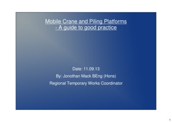
University of KansasMarch 1, 2018Engineering ConferenceCrane Girder DesignCrane Girder DesignJules Van de Pas P.E.,S.E.CSD Structural EngineersCrane Girder DesignPresenter:Jules Van de Pas P.E.,S.E.Learning Objectives: Discuss the design of crane girder connections for goodfatigue performance. Demonstrate the design of industrial crane girders. Demonstrate designof crane girders toresist seismic loads.1
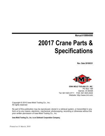
University of KansasMarch 1, 2018Engineering ConferenceCrane Girder DesignCrane Girder DetailsProper detailing is the key to good fatigue performanceThe vast majority of crane girder performance issues occurat the crane girder to column connection.3Column or Bracket Support Do not use framed or clip angle type connections. Extend bearing stiffeners the full height of the girder Weld to the girder top flange with full penetration welds orwelds sized for the wheel loads. Weld to the girder web and bottom flange with properlysized continuous fillet welds.42
University of KansasMarch 1, 2018Engineering ConferenceCrane Girder DesignCrane Column Cap Plates Allow girder end rotation– avoid thick cap plates– place the bolts outside of the column flanges. Do not use knee braces Allow for adjustment in placing the crane girder.5Tie Back Design63
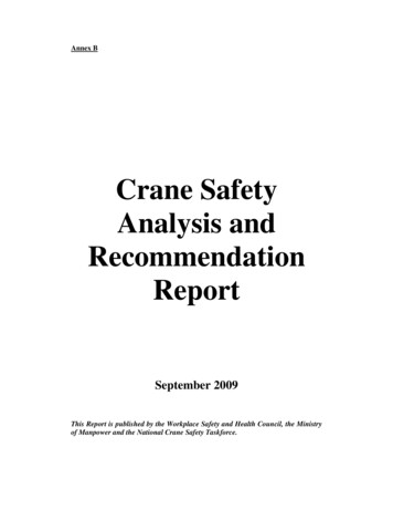
University of KansasMarch 1, 2018Engineering ConferenceCrane Girder DesignGirder LacingUsing a truss to stabilize the topand bottom flange for lateral loadsDetail to avoid creatinginadvertent continuity in adjacentspansConsider bending in the anglesdue to relative vertical movement.7Problematic Girder Support84
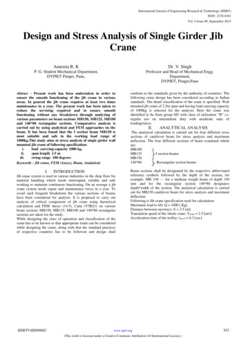
University of KansasMarch 1, 2018Engineering ConferenceCrane Girder DesignCrane Girder Example9Cross SectionT/roof 60’T/rail45’-11”50 T CRANE50 T CRANE120’105
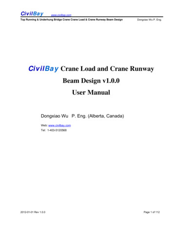
University of KansasMarch 1, 2018Engineering ConferenceCrane Girder DesignBuilding Footprint1160 ft Runway Girder:Center Condition:CRANE GIRDERCRANE GIRDERUse angles to create a truss at thetop and bottom of the girders.126
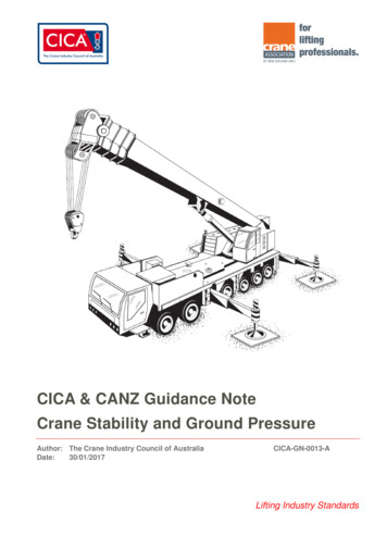
University of KansasMarch 1, 2018Engineering ConferenceCrane Girder DesignCodes, Standards & Ref’s Building Code: IBC 2015 Minimum Design Loads For Buildings AndOther Structures (ASCE 7-10) Guide for the Design and Construction ofMill Buildings (AISE Tech Report No. 13,2003) Industrial Buildings Roofs to Anchor Rods2nd ed. (AISC Steel Design Guide Number7, 2004)13Design of a Runway GirderCrane capacity 50 tons(CMAA Class D)Bridge weight 90.8 kipsTrolley and hoist weight 31.2 kipsWheel load 78 kips(Maximum with lifted load)Wheel spacing 11.0 ft.Rail weight 175 lbs./yardVertical impact 25% of wheel loadsLateral load 20% of lifted load trolley and hoistLongitudinal load 10% of the maximum wheel loads.147
University of KansasMarch 1, 2018Engineering ConferenceCrane Girder DesignPerformance RequirementsCrane Girder Deflection Limits– Vertical L/800– Horizontal L/400Service Life-500,000 cyclesCMAA Class D:15Load CombinationsStrength Design Loads: ASCE 7-10Chapter 2 Section 2.3 Basic Load Combinations2) 1.2D 1.6LChapter 12 Section 12.4 Seismic Load Effects, Combinations5a) (1.2 0.2SDS)D ρQE L .2S5a) (1.2 0.2SDS)(D Cd) ρQEServiceabilityVertical wheel loads without impact & 100% lateral loadFatigue Life Design Loadwheel loads without impact (one crane)1650% of maximum lateral load (one crane)8
University of KansasMarch 1, 2018Engineering ConferenceCrane Girder DesignSeismic Loads–––––Spectral Acceleration, Ss:Spectral Acceleration, S1:Occupancy Category:Site Class:Importance Factor, I:1.054 G0.400 GIID1.0S MS Fa S s (1.1)(1.054 ) 1.16 g S M 1 Fv S1 (1.6 )(0.400 ) 0.640 g2222S D1 S M 1 (0.64 ) 0.43 gS DS S MS (1.16 ) 0.77 g3333- Seismic Design Category D17Design of a Runway GirderEvaluate for Seismic Loads: Design Crane Girder to resistloads based on ASCE 7-10 Chapter 13: Seismic DesignRequirements for Nonstructural Components .1 2 2.5, 3.5(Table 13.5-1 “Other flexible components, Highdeformability element and attachments) 1.0 (section 13.1.3)# 45.9 ft.h 60.0 ft.* * .770189
University of KansasMarch 1, 2018Engineering ConferenceCrane Girder DesignRunway Girder -Seismic .-. (.//)0.12.31 2.456.6 .567Total Bridge Trolley 90.8 k 30.2 k 122 k. .56(122 BC D) 68.3 k.KL 46.M N6.-/FGHHI 17.1 k. (ult.) 35.8 kips/wheel (Vertical Load)For Comparison: Max wheel load 78 k.Fulat 1.6*.2(100 31.2) 42.0 kip Fulat/wheel 10.5 kips19LRFD Design of 60’ Crane GirderDeflection requirements: Locate wheel loads symmetricallyplaced about the girder centerline. a 24.5 ft. (294 in.)Vertical: L/800 (60 ft.)(12)/800 0.9 in.Ixreqd: Δ] - a3b2 423 7202a 78 29424 29000deHfL 39849 39849 44277 740d593 d 50,400Ch4Δ] .9Δ] 4 2942 398492010
University of KansasMarch 1, 2018Engineering ConferenceCrane Girder DesignDesign of 60 ft Runway GirderCalculate Moments & Forces 1.2D 1.6L:DL (Girder Rail Clamps) 593 175/3 20 671 lbs/ftMDL (1/8)wL2 (1/8)(0.67 kips/ft)(60 ft)2 302 k-ftMLL :See table 3-23 case 44opp 1.25 78(60 11/2)- 2413 kip ft.2(60)Mux 1.2*MDL 1.6*MULL 1.2*302 1.6*2413 4223 k-ft.21Design of 60 ft Runway GirderCalculate Moments & Forces 1.2D 1.6L :Muy s.5 5.5(60-(56) 11/2)- 261 k ft. (total )Calculate chord force in truss:Pu (-5s). 47 k (top flange)Bending Between the panel points:Muy 49 k ft. (per model)2211
University of KansasMarch 1, 2018Engineering ConferenceCrane Girder DesignDesign of 60 ft Runway GirderAvailable Moment: Lb 15 ft., Lr 63.9 ft., Lp 13.4 ft.See table 3-2b bu bvwGHeHxyeH zDH {fz Cyh 2 2:bu b)] oo} Ku [o (o .7 * )(bv b234015 13.4oh 1.0[11400 (11400 .7(50)())()]1263.9 13.4 11400oh 11255 k-ft.φoh .9 11255 10130 k-ft23Design of 60 ft Runway GirderCheck combined forces on girder 1.2D 1.6L ‚s. s 37.3 „} 40.7 3.23 16.7 2195 Bv .M-φ Mny φFyZy/2 (.9)(50)(481)/2)/12 902 kip-ft.φ Mnx 10130 kip-ft.Interaction per AISC Chapter Hˆ‰ˆ ‰ˆ 2φ } φ‰} φ‰} 1.0/- -s4. --Ns6sN6 446- .51 OK2412
University of KansasMarch 1, 2018Engineering ConferenceCrane Girder DesignDesign of 60 ft Runway GirderEvaluate for Seismic Loads (Continued):Recall: MDL 302 B x .opp 2413 B x . (1.25*Wheel load of 156 kips)(For Lat. wheel loads of 10.6 kips)Pu 69 BMuy 49 B x . (For Lat. wheel loads of 10.6 kips)For load Case 5a:(1.2 .2SDS)(D Cd ) ρQEMux (1.35)[(302 ) (35.8/(1.25*156))(2413)] 1006 k-ft.(s/.s)Pu (s6.5) 47 76 kip (total)Muy (17.1/10.6)49 kip ft. 79 k-ft.25Design of 60 ft Runway GirderFor Load Case 5a W40 Crane GirderInteraction per AISC Chapter Hˆ‰ˆ ‰ˆ 2φ } φ‰} φ‰} 1.0/5s664 - -s4.s6sN6 /446- .21 OK2613
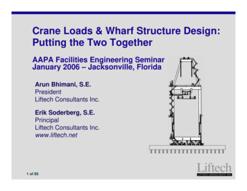
University of KansasMarch 1, 2018Engineering ConferenceCrane Girder DesignDesign of 60 ft Runway GirderCheck Limit states for: Shear Web Local YieldingJ10.2 Web Local CripplingJ10.3 Web Sidesway Buckling J10.4(wheel loads)(wheel loads)(wheel loads)T.O.RTop of Flange6”lb 12”27Design of 60 ft Runway GirderCheck Web Local Yielding- AISC J10.2 W40x593φ 1.φ Rn φFywtw (5k lb)J10-2 (1.0)(50 ksi)(1.79in.)[(5)(4.41 in.) (12 in.)] 3047 kips156 kips 3047 kips okT.O.RTop of Flange6”lb 12”2814
University of KansasMarch 1, 2018Engineering ConferenceCrane Girder DesignDesign of 60 ft Runway GirderCheck Web Local Crippling- AISC J10.3 W40X593tf 3.23 in., tw 1.79 in., d 43.0 in., lb 12 in. φ .75‚’φRn φ. 8 F - [1 3( ‘u)( ’“)s. ]”φRh .75 .8 1.792[1 3 “’”’“sN.6(s./4 s.) ]N.-NJ10-4-4666(.6)(N.-N)s./4φRn 4184 156 k. OK29Design of 60 ft Runway GirderCheck Sidesway Web Buckling AISC J10.4(b) compressionflange not restrained against rotationW40x593: h/tw 19.1,bf 16.7 in.,Lb 180 in.(h/tw)/(Lb/bf) 19.1/(180/16.7) 1.77 1.7Sidesway web buckling limit state OK3015
University of KansasMarch 1, 2018Engineering ConferenceCrane Girder DesignLaced Crane Girders Horizontal truss attached to the top flange of thegirder and a back up girder to form a truss to stabilizethe top flange of the girder– usually economical for spans over 40 feetHorizontal loads for the 60’ Girder Lacing Seismic Loads Crane Lateral Loads AIST Bottom flange bracing criteria31Crane Girder LacingDetermine brace force:Seismic:lateral crane load:Fp 17.1 kips/wheelFu 1.6*6.6 10.6 kips/wheel):Rend 17.1(2)(52.5 41.5)/60 53.6 kipsMax. Angle Force Pu 53.6(112/66) 90.9 kips3216
University of KansasMarch 1, 2018Engineering ConferenceCrane Girder DesignRunway Girder DesignDetermine brace force: 2.5% of W40 flange forceAverage fb in bottom flange 19.98 ksi(Ult. load level)Brace force .025fbA .025(19.98)(3.23 in.)(16.7) 26.9 kipsApplied at mid spanMax Angle Force (26.9/2)(112/66) 22.8 kips 90.9 kipsSeismic Load Controls33Design of 60 ft Runway GirderAngle Strength: L 9.33 ft.Try 2L4x4x5/16 AISC Manual Table 4-8:φPn 100.9 kips 90.9kips OK3417
University of KansasMarch 1, 2018Engineering ConferenceCrane Girder DesignDesign of 60 ft Runway GirderCheck Connection for applicable limitstates: Bolt shear (J3.1) Bolt bearing (J3.10) Weld and base metal shearrupture (J2.4, J4.2) Block shear on angle and gusset(J4.3) Tensile rupture on net angle section(D2) Fatigue per Appendix 3. *35Design of 60 ft Runway GirderFatigue Condition: Service Load 50% of max lateral loads(.5*6.6 kips/wheel):KK3.33.3Rend 3.3(52.5 41.5)/60 5.2 kipsAngle Force Ps 5.2(112/66) /-8.8 kips3618
University of KansasMarch 1, 2018Engineering ConferenceCrane Girder DesignFatigue EvaluationCheck Connection at the bolt: Base Metal at net section of high strengthbolted joints designed Rbearingresistance, but fabricated and installed toall requirements for slip criticalconnections.Section 2: Stress Category B } v— 1000( ” ).NNN — 1000(›œs).NNN.66,666Cf 12Fth 16 Ksinsr 500,000 cycles 28.9 ksi37Fatigue EvaluationCheck Connection PL. at the bolt:5/8” x 6” plate (1)1 1/4” dia. A325 BoltAnet .625(6-1.375) 2.89f (2)(8.8)/2.89 6.1 ksi 28.9 ksi OK ( 16 ksi)Also check net section on the angles3819
University of KansasMarch 1, 2018Engineering ConferenceCrane Girder DesignFatigue EvaluationCheck connection at the gusset weld:Section 5.7 Base Metal and weld metal attransverse end connections of tensionloaded plate elements.(2) Cases require evaluation Crack initiating from the weld toe Crack initiating from the weld root39Fatigue EvaluationCheck connection at the gusset weld (continued):Crack initiating from weld toe Stress Category CCf 4.4—Fth 10 Ksi 1000(. .NNN) }—›œ— 1000(.).NNN.66,666 20.7 ksiCrack initiating from weld root Stress Category C ‘’— 1000 xCI(. .NNN)}—Rfil .06 .72(w/tp).’s5/Fth N/A4020
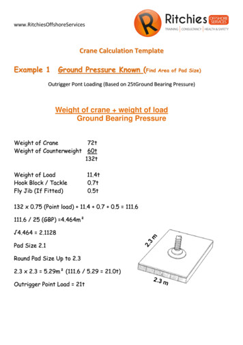
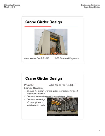
University of KansasMarch 1, 2018Engineering ConferenceCrane Girder DesignFatigue EvaluationCheck connection at the web weld (continued):Section 5 Crack initiating from weld root Stress Category C‘’Rfil .—06 .72(.3125/.625). .454.5-. s5/ 1000(.454)(.).NNN.66,666 9.4 ksi(CONTROLS)5/16 fillet weld capacity 9.4ksi(.3125*.7071) 2.08 k/in.Elastic analysis of the L shaped weld group f .7 k/in.41Fatigue EvaluationCheck fatigue at the welded plate tothe girder web and tension flange. Impact of the stress riser on thestrong axis bending strength.Table A-3.1, Section 5.7, “Basemetal of tension loaded plateelements and on girders and rolledbeam webs or flanges at toe oftransverse fillet welds adjacent towelded transverse stiffeners.”4221
University of KansasMarch 1, 2018Engineering ConferenceCrane Girder DesignFatigue Evaluation43Fatigue EvaluationSection 5.7 (stress cat. C) FSR (} ” )0.333 FTHCf 44x108, FTH 10 ksiFSR (44x108/500,000)0.333 20.6 ksi—fb Mll/Sx (1931 kip-ft.)(12)/ 2340 in.3 9.9 ksi 20.6 ksi okFor Comparison without the welded attachmentSection 1.1 (stress cat. A)Cf 250x108, FTH 24 ksiFSR (250x108/500,000)0.333 36.7 ksi4422
University of KansasMarch 1, 2018Engineering ConferenceCrane Girder DesignGIRDER DESIGNCONCLUSION1. Follow Good Detailing Practices2. Design for serviceability then strength3. Evaluate fatigue life per AISC Appendix 34523
01.03.2018 · Crane Girder Design Crane Girder Details Proper detailing is the key to good fatigue performance The vast majority of crane girder performance issues occur at the crane girder to column connection. 3 4 Column or Bracket Support Do not use framed or clip angle type connections. Extend bearing stiffeners the full height of the girder