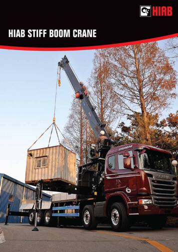
Transcription
Manual # 9990456020017 Crane Parts &SpecificationsRev. Date 20100331IOWA MOLD TOOLING CO., INC.PO Box 189Garner, IA 50438Tel: 641-923-3711 FAX: 641-923-2424Website: http://www.imt.comCopyright 2010 Iowa Mold Tooling Co., Inc.All rights reservedNo part of this publication may be reproduced, stored in a retrieval system, or transmitted in anyform or by any means, electronic, mechanical, photocopying, recording or otherwise without theprior written permission of Iowa Mold Tooling Co., Inc.Iowa Mold Tooling Co., Inc. is an Oshkosh Corporation Company.Printed on 31 March, 2010
iContentsRevisions . wed Position and Mounting Dimensions.9Geometric Configuration .10Capacity Chart .11Minimum Chassis Specifications.12Crane Reference13Crane Assemblies & Weldment Part Numbers.1420017 Grease Zerk Locations .15Recommended Spare Parts .1620017 Crane Installation.1720017 Hydraulic Installation .1920017 Winch Troubleshooting .20Parts21Parts Information .22Base, Mast & Boom Assemblies & Cylinders.24Base & Outrigger Assembly (41704444) .24Outrigger Cylinder (3C323911) .27Mast Assembly (41704436).29Inner Boom Assembly (41704437) .30Inner Cylinder (3D216821) .32Outer Boom Assembly (41704439).34Outer Cylinder (3C221820).35Extension Boom Assembly (41704440) .37Extension Cylinder (3B223820) .38Hydraulics.39Hydraulic Schematic, Manual (91704442).39Hydraulic Schematic, Radio .41Hydraulic Kit, Crane/Tirehand (99903032).42Hydraulic Kit, Crane Rotation (99903033) .43Hydraulic Kit, Curbside Outrigger (99903035).44Controls-Radio.45Valve Bank, Radio (51719464) .45Valve Bank, Outrigger (51715470) .46Capacity Shutdown Kit, Radio (31717514).47Hydraulic Shutdown Kit, Radio (99903465).48Relief Valve Assembly, 12V Radio (73055278) .50Relief Valve Assembly, 24V Radio (73055298) .50
iiContentsControls-Manual .51Valvebank, Manual (51710120) .51Capacity Shutdown Kit, Manual (31717169) .52Hydraulic Shutdown Kit, Manual (31713789) .53Hydraulic Overload Kit, 2-Function, Manual (51717130) .55Hydraulic Overload Kit, 3-Function, Manual (51717128) .57Control Kit, 8-Function, Manual (90704441).59Control Kit, 11-Function, Manual (90710603).61Electrical.63Electrical Schematic (99903557).63Light Kit (51717977).64Electrical Control Cabinet (41718269).65Electrical Control Box Assembly (41718269-2) .67Harness, Crane Mast/Radio Control, 12V (77441197).70Chassis Wiring (99903160) .71Radio Remote Kit - Nova (73733481).73Miscellaneous .74Decal Kit (95708880) .74Installation Kit (93704445) .76Saddle Kit (31704684).78Auxiliary Outrigger Kit, PO/PD Radio (31714072-1).79Auxiliary Outrigger Kit, PO/PD Street Side (31714072-2).80Auxiliary Outrigger Kit, PO/PD Curb Side (31714072-3) .81General Reference83Inspection Checklist.84Deficiency / Recommendation / Corrective Action Report .88Wire Rope Inspection & Replacement.90Hook Inspection.91Holding Valve Inspection .92Anti-Two-Block Device Inspection.92Thread Torques.94Turntable Bearing Thread Tightening Sequence .97Turntable Bearing Inspection for Replacement .98Turntable Bearing Tilt Test.98
733481,99903557ECN 11211 - Update elec system for engine start function on OTRproduct line.iii
5CHAPTER 1IntroductionGENERALThis manual will help you operate your IMT crane correctly and safely. The manual does notreplace any government regulations, safety codes or insurance carrier requirements. Read andunderstand the manual and all safety procedures for this crane prior to operation.WARNINGFAILURE TO READ, UNDERSTAND AND FOLLOW ANY SAFETY PROCEDURES FORTHIS EQUIPMENT MAY RESULT IN DEATH, SERIOUS INJURY, OR EQUIPMENTDAMAGE.Use caution and common sense. Refer to ANSI/ASME B30.22, the standard for Mobile andLocomotive Cranes, for more information on crane design and test criteria. (Contact AmericanSociety of Mechanical Engineers at www.asme.org for information on ANSI/ASME B30.22.)Crane operators must also be familiar with OSHA 29CFR, Subpart N, Article 1926.550 and CALOSHA Title 8, Article 93 (California).CRANE AND SAFETY EQUIPMENT MODIFICATIONSDo not modify your crane with anything other than IMT approved equipment. If in doubt, contactIMT prior to making modifications. DO NOT alter or modify any safety device! All safety devicesmust be inspected, tested and maintained in proper working condition.Decals regarding crane safety and operation are safety equipment and must be maintained.Decals must be kept clean and legible.OWNER RESPONSIBILITIESThe owner must maintain and operate this unit for the safest working conditions possible. Hemust follow existing Federal, State, and Local codes and regulations governing the safe use andmaintenance. He must make sure anyone involved in equipment operation understands how tooperate and maintain the crane safely. Contact IMT or your IMT distributor for clarification.
620017 Crane Parts & Specifications Manual # 99904560MANUAL STRUCTUREThroughout this manual, three means are used to highlight information. They are NOTEs,CAUTIONs and WARNINGs and are defined as follows:NOTEA NOTE adds additional information or provides emphasis.CAUTIONA CAUTION indicates the strong possibility of equipment damage or premature equipmentfailure.WARNINGA WARNING is used when there is the potential for death or personal injury.WARRANTYThe equipment warranty on this unit will be void on any part of the unit subjected to misuse dueto overloading, abuse, lack of maintenance and unauthorized modifications. No warranty verbal, written or implied - other than the official, published IMT new machinery and equipmentwarranty is valid with this unit.NOTICE TO THE OWNER / USERIf the crane is involved in a property damage accident, contact your IMT distributor immediatelyand provide them with the details of the accident and the serial number of the equipment. If anaccident involves personal injury, immediately notify your distributor and IMT Technical Supportat:IOWA MOLD TOOLING CO., INC.500 HWY 18 WESTGARNER, IA 50438641 - 923 - 3711
7CHAPTER 2SpecificationsIn This ChapterSpecifications .7Stowed Position and Mounting Dimensions .9Geometric Configuration .10Capacity Chart.11Minimum Chassis Specifications.12
820017 Crane Parts & Specifications Manual # 99904560SpecificationsGENERAL SPECIFICATIONSCRANE RATING* (ANSI B30.22)MAXIMUM CRANE RATING**HORIZONTAL REACH (From centerline ofrotation)HYDRAULIC EXTENSIONMANUAL EXTENSIONVERTICAL REACH (From mounting surface)VERTICAL REACH (From ground/ 41" frameheight)CRANE WEIGHTOUTRIGGER SPANOUTRIGGER PADS199,538 ft-lb (27.59 tm)200,000 ft-lb (27.65 tm)17'-0" (5.18 m)40" (101.6 cm)None24'-11
CRANE WEIGHT 7,630 lb (3,460 kg) OUTRIGGER SPAN 15'-0" (4.57 m) OUTRIGGER PADS 12" x 19" (30.5 cm x 48.2 cm) CRANE STORAGE HEIGHT (with 12" flat-bed body - from mounting surface) 8'-9" (2.67 m) CRANE STORAGE HEIGHT (with 12" flat-bed body - from ground / 41" frame height) 12'-2" (3.71 m) MOUNTING SPACE REQUIRED (Allow 4" between the truck cab and crane base for swing
