Transcription
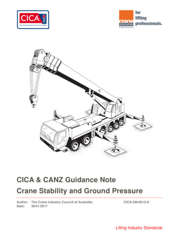
CICA & CANZ Guidance NoteCrane Stability and Ground PressureAuthor: The Crane Industry Council of AustraliaDate:30/01/2017CICA-GN-0013-ALifting Industry Standards
Table of Contents1.Introduction . 32.Responsibility . 33.Loads and Forces . 43.1 Crane loads . 43.2 Rigging gear . 43.3 Object loads . 43.4 Load cases . 43.5 Calculation. 43.6 Lifting on rubber . 93.7 Articulated crane . 93.8 Manufacturer’s software . 93.9 Theoretical calculations . 104.Crane Mats . 104.1 Crane mat size calculation - uniform pressure . 104.1.1 Example 1 . 104.1.2 Example 2 . 114.2 Crane mat strength and stiffness . 115.Ground Condition . 115.1 Ground capacity . 115.2 Trench diagram . 126.Reference . 137.Further Information . 14Appendix A – Articulated Crane Axle Loading . 15Appendix B – Manufacturer Software Calculation Examples Outrigger Pad Load . 17Disclaimer and CopyrightThis CICA&CANZ Guidance Note has been compiled for general information only, is not to be considered as a substitute forprofessional advice, and should not be treated as an exhaustive statement on the subject. The Crane Industry Council ofAustralia (CICA) and the Crane Association of New Zealand (CANZ) accept no responsibility for the accuracy, completeness orcurrency of the material included in this Guidance Note. Users of this Guidance Note are encouraged to obtain professionaladvice and to exercise their own skill and care in relation to any of its material.CICA and CANZ disclaim any and all liability or responsibility for any loss or damages arising out of any use of, or reliance on,this Guidance Note. This Guidance Note is copyright. Readers may use and reproduce this material in an unaltered form onlyfor non-commercial use within their own organisation. Apart from any use permitted under the Copyright Act 1968, all otherrights are reserved.CICA-GN-0013-APage 2 of 23Lifting Industry Standards
1. IntroductionMany factors need to be considered when safely setting-up mobile cranes on site. Cranestability often depends on the integrity of the ground on which it stands. Effectiveassessment of ground conditions is essential to assist with safe set up and operation ofcranes. To reduce the risk of crane accidents as a result of improper crane set-up, planningactivities shall be carried out by a competent person(s) to assess the capability of the groundto withstand the loads and pressures imposed by the lifting equipment.All parties who are involved in the planning, set up and use of cranes on site must be awareof the fundamental criteria, planning issues and risk assessments that are needed to ensurelifting operations proceed in a safe and stable manner.This Guidance Note provides general guidance to assist on: determining the load exerted by mobile crane outriggers or crawler crane tracksdetermining the suitability of the crane mats, andbearing capacity of different types of soil.2. ResponsibilityAs with all activities on construction sites, the effective management of the safety of liftingoperations can only succeed if all parties involved are clear about their roles andresponsibilities. It is essential for all persons undertaking these roles to be competent,having relevant up-to-date training and the qualifications and experience appropriate to theoperations for which they are responsible.The responsibilities for undertaking the various activities involved in ground assessment areset out below: A person conducting a business or undertaking (PCBU) that includes the carrying outof construction work (i.e. the principle contractor in control of the project site) hasoverall responsibility for the safety of all personnel on site. They should ensure thatwhere a crane is being used to carry out a task, adequate steps have been taken toensure the stability of the crane during transport onto site, set up, use, movement,maintenance, dismantling and removal from the site. PCBU should provide accurategeotechnical report for the site ground condition or other relevant information forcrane stability to the worker responsible for the lifting operations if this is necessaryfor the safe operation of the lifting activity. It is usually the PCBU’s responsibility tomake sure the ground is safe to work on.A worker who carries out work for a PCBU (i.e. the person or company in control of alifting operation) is responsible for all aspects of planning, supervision and executionof the lifting operation, including ensuring that the ground or structure on whichequipment stands will take the loads imposed by the plant. This does not mean thatthe worker has to be an expert in ground assessment, they must however takereasonable steps to satisfy themselves that the information provided by the person incontrol of the site is relevant and appropriate. The worker should have the necessaryconfidence and authority to carry out their duties effectively and safely.Where doubt exists as to the accuracy or sufficiency of the information provided it is theresponsibility of the worker to ensure that the lifting operation does not proceed until thedoubt has been satisfactorily resolved.CICA-GN-0013-APage 3 of 23Lifting Industry Standards
3. Loads and ForcesAssessment of loads and forces imposed by the crane on the ground shall be conductedduring the planning stage. The following loads and factors should be considered whenassess load and forces.3.1 Crane loadsInformation on crane loads and forces can be found from sources including technical datapublished by the manufacturer. Different rigging configurations of the crane, i.e. usingdifferent combination of counterweights or fly jibs in the lift operation may associate withdifferent crane weight distribution. Refer to the manufacturer data to determine what riggingconfiguration is representative and what weights and loads apply. Information on individualweight and center of gravity of the crane components should be obtained and applied in theload calculations.3.2 Rigging gearCorrect weight of lifting accessories such as chains, shackles, spreader bars, etc. shall beadded up and included as part of the vertical load when calculating loads and forces.3.3 Object loadsAlways obtain accurate information (weight, density, overall dimensions and center ofgravity) about the load to be lifted, do not guess and do not use the crane as a ‘weighingscale’.3.4 Load casesDifferent load cases can impose different loads and forces to the ground (see Figure 1 andFigure 2). During the lift operation, crane boom length, slew angle and slew arc may vary,these will change the forces on the outriggers. It is often assumed that the maximum loadsand forces will occur during operation at maximum capacity, this is not always the case, forexample, outrigger loads could be at its highest without any load on the hook at minimumradius due to backward moment from the counterweight [1]. In some load cases, total load ofthe crane may be imposed largely on one outrigger or one crawler track when the boom orcounterweight is slewed over that outrigger or over the side of that track.3.5 CalculationCalculation of the load exerted by the crane outrigger or track should consider both thevertical load (from the crane loads, rigging gear loads and object loads) and the load causedby the moment acting on each outrigger or track under different load cases (see Figure 1and Figure 2). Refer to detailed examples of calculations included in Cranes and Derricks [2]for all-terrain and crawler cranes.In addition, other loads to consider include: dynamic loading due to wind pressurelateral loading due to incorrect set-up or different settlement of supportsdynamic loads caused by slewing or a swinging lifted loaddynamic loads caused by crane travelling with loademergency loadsRefer to AS1418[3] for values of the dynamic load factors.CICA-GN-0013-APage 4 of 23Lifting Industry Standards
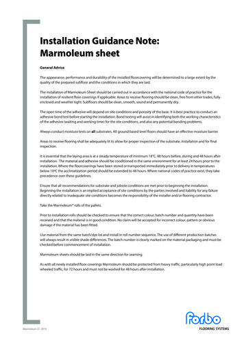
No Load On HookFrontLoad On HookRearFrontHighest Load on front outriggerHighest Load on rear outrigger.RearFrontRearHighest load on outrigger undercounterweight.FrontFrontRearHighest load on outrigger under jib.RearHighest load on outriggers undercounterweight.RearFrontHighest load on outriggers nearest load. greatest pressure imposed on this outrigger for this lifting configuration intermediate pressure imposed on this outrigger for this lifting configuration smallest pressure imposed on this outrigger for this lifting configurationFigure 1 (a) – Outrigger Load Change due to Different Load CasesCICA-GN-0013-APage 5 of 23Lifting Industry Standards
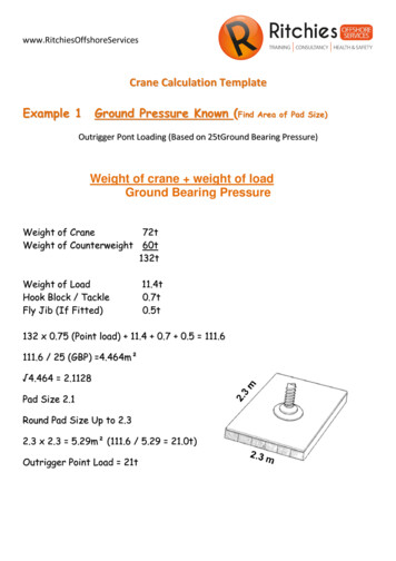
No Load On HookLoad On HookHighest Load on front outrigger.Highest load on outrigger undercounterweight.Highest load on outrigger under jib.Highest load on outriggers nearest load. greatest pressure imposed on this outrigger for this lifting configuration intermediate pressure imposed on this outrigger for this lifting configuration smallest pressure imposed on this outrigger for this lifting configurationFigure 1 (b) – Outrigger Load Change due to Different Load CasesCICA-GN-0013-APage 6 of 23Lifting Industry Standards
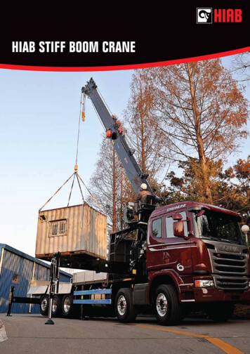
No Load On HookLoad On HookWith no load on the hook the pressure is athighest under the rear end of the tracks dueto the counterweight.With load on the hook, the pressure changesfrom triangular to trapezoidal distribution.With no load on the hook and the jib luffingdown, the pressure changes from triangularto trapezoidal distribution.With load on the hook and the jib luffingdown the pressure changes from trapezoidalto triangular distribution, with the highestunder the front end of the tracks.Figure 2 (a) - Crawler Track Pressure Change due to Different Load CasesCICA-GN-0013-APage 7 of 23Lifting Industry Standards
With no load on the hook the pressure is athighest under the rear of the tracks due tothe counterweight.With the jib in line with the tracks and a loadon the hook there will be an equal triangularor trapezoidal loading under each track.As the jib is slewed around until it is over theend of one track, the pressure increasesunder that track.If the jib is slewed until it is at right angle tothe tracks the pressure becomes arectangular distribution with the tracknearest the load having the greatestpressure.Figure 2 (b) - Crawler Track Pressure Change due to Different Load CasesCICA-GN-0013-APage 8 of 23Lifting Industry Standards
3.6 Lifting on rubberCrane operated without the outriggers extended is referred to as “operating on rubber”.When operating on rubber, follow the setup procedure and operating limitations specified bythe crane manufacturer. On rubber load chart shall be used if operating on rubber. Tireconditions need to be properly checked and tires need to be inflated per the manufacturer’sspecifications.Where the load will be picked from and where it will be placed must also be considered, soground conditions for the picking and placing area can be assessed.3.7 Articulated craneIt is recommended that articulated crane loads should be calculated or checked by anengineer through theoretical calculation. Refer to Appendix A for reference for articulatedcrane axle loading.3.8 Manufacturer’s softwareMany crane manufacturers supply software and tables that can give accurate andcomprehensive load data when these resources are used properly.Table 1 is a list of some of the available software from obelco-kenki.com/en comLICCON work /
For example, if the lift study indicates that a crane imposes a maximum load of 48 tonnes on the outrigger, and the available crane mat size is 1.7m x 1.7m. Then the pressure imposed by the crane to the ground can be calculated by: Force 48 tonnes x 9.8m/s2 470.4 kN Area of the crane mat 1.7m x 1.7m 2.89m2 Pressure . 162.8 kN/m2