Transcription
International Journal of Engineering Research & Technology (IJERT)ISSN: 2278-0181Vol. 4 Issue 09, September-2015Design and Stress Analysis of Single Girder JibCraneAmreeta R. KDr. V. SinghP. G. Student Mechanical Department,DYPIET Pimpri, Pune,Professor and Head of Mechanical Engg.Department,DYPIET, Pimpri,PuneAbtract - Present work has been undertaken in order toensure the smooth functioning of the jib crane in variousareas. In general the jib crane requires at least two timesmaintenance in a year. The present work has been taken toreduce the servicing required and to ensure smoothfunctioning without any breakdown through analyzing ofvarious parameters on beam sections MB150, MB125, MB100and 140*80 rectangular sections. Comparative analysis iscarried out by using analytical and FEM approaches on thebeam. It has been found that the I section beam MB150 ismost suitable and safe in the working load range of1000kg.This study aims at stress analysis of single girder wallmounted jib crane of following specification:i.load carrying capacity 1000 kg,ii.span length 2.5 miii.swing range 180 degreesKeywords - Jib crane, FEM (Ansys), Beam, Analytical.conform to the standards given by the authority of countries. Thefollowing crane design has been considered according to Indianstandards. The detail classification of the crane is specified. Wallmounted jib crane of 2.5m span and having load carrying capacityof 1000kg is selected for the analysis. Here the crane wasidentified to be from group M5 with class of utilization “B” i.e.regular use on intermittent duty with moderate state ofloading/stress.I.INTRODUCTIONJib crane system is used in various industries in the shop floor formaterial handling which needs interrupted, reliable and safeworking to maintain continuous functioning. On an average a jibcrane system needs repair and maintenance twice in a year. Toavoid such frequent breakdown the various sections of beamshave been considered for analysis. It is proposed to carry outanalysis of critical component of jib crane using theoreticalcalculation and FEM Ansys (14.5), Catia (V5R21) on variousbeam sections MB150, MB125, MB100 and 140*80 rectangularsections are taken for the study.While designing the class of operation and classification of thecrane has to be known so that appropriate loads can be consideredwhile designing the crane, along with that the standard practicesof respective countries has to be followed and design shallIJERTV4IS090682II.ANALYTICAL ANALYSISThe analytical calculation is carried out for four different crosssections of cantilever beam for stress analysis and maximumdeflection. The four different sections of beam examined whichare:MB100MB125I section beamsMB150140*80Rectangular section beamsBeam sections shall be designated by the respective abbreviatedreference symbols followed by the depth of the section, forexample: MB 150 — for a medium weight beam of depth 150mm and for the rectangular section 140*80 designatesdepth*width of the section. The analytical calculation is carriedout for MB150 cantilever beam for stress analysis and maximumdeflection.Following is Jib crane specification used for calculation:Maximum load to lift: Q 1000 [ Kg]Distance between raceways: S 2.5 [m]Translation speed of the whole crane: Vtrans 2.5 [m/s]Acceleration time of the trolley: t accel 6.3 [sec]www.ijert.org(This work is licensed under a Creative Commons Attribution 4.0 International License.)932
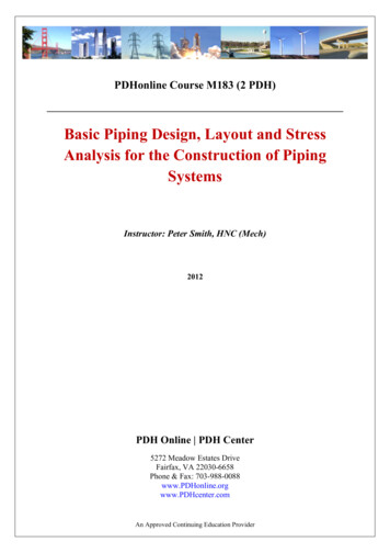
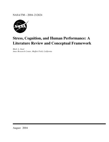
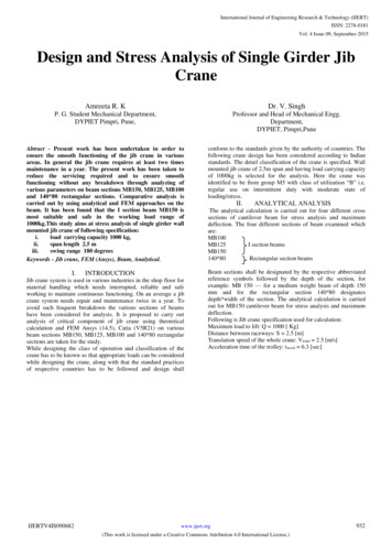
International Journal of Engineering Research & Technology (IJERT)ISSN: 2278-0181Vol. 4 Issue 09, September-2015i.𝑚𝑚𝑎𝑥,𝐼 1149 [N/m]𝑚𝑚𝑎𝑥,𝐼𝐼 25015.5 [N/m]𝑚𝑚𝑎𝑥,𝐼𝐼𝐼 46.46 [N/m]As the loads I and II are vertical and loads III and IV arehorizontal, different section modulus (W) are used. Stressescreated by the flexure moment are:𝑚𝐼1149σ𝐼 𝑤𝑥95.7 10 6 12 106 [N/𝑚2 ]Cantilever I-Type beam, MB150, carrying load -1000Kgσ𝐼 12 [𝑀𝑃𝑎]𝑚𝐼𝐼25015.5σ𝐼𝐼 𝑤𝑥95.7 10 6σ𝐼𝐼 261.3 [𝑀𝑃𝑎]σ𝐼𝐼𝐼 σ𝐼𝐼𝐼 3.8 [𝑀𝑃𝑎]Stress on the most critical section:σ σ𝐼 σ𝐼𝐼 σ𝐼𝐼𝐼σ 12 261.3 3.8σ 277.1 [𝑀𝑃𝑎]Stress acting on beam is 277.1 [MPa]Figure no 1: Cantilever I-type ���𝐼𝐼46.46 𝑤𝑦12.5 10 67180000y Table no 1: Design details of I beam of size MB150𝑃𝐿33𝐸𝐼𝑋𝑋SectionalWx 95.7 cm3 95.7 * 10-6 m3ModulusWy 12.5 cm3 12.5 * 10-6 m3Self Weight:𝑞𝑔 ρ. S 147.08 [N/m] 147.08 * 2.5 367.7 [N]Service Load:P 10006.2 NHorizontal load due to the own weight in the translation of thecrane (SH):𝑎𝑞𝐻 𝑞𝑔 𝑊𝐿38𝐸𝐼𝑋𝑋Maximum deflection of the beam is 0.0345mmRectangular section beam, 140*80, carrying load - 1000Kgii.𝑉tras 𝑞𝑔 𝑡acc𝑔𝑞𝐻 14.87 [N/m]The flexure moments created by the loads in most critical section(L/2) are:𝑞𝐻 .Table no 2: Design details of rectangular sectionbeam of size 140*80Sectional area S 16.55 * 10-4 m2SectionalWx 61.37 * 10-6 m3ModulusWy 45.10 * 10-6 m3As it was seen in the theory it is necessary to calculate the ownweight, the service load, the horizontal load due to the ownweight as the result of the crane translation.Service Load:P 10006.2 NHorizontal load due to the own weight in the translationof the crane (SH):𝑎𝑉tras 𝑞𝑔𝑞𝐻 𝑞 𝑔𝑡acc𝑔𝑞𝐻 12.88 [N/m]The given loads (service loads), the own weight of the structureand the movements of the crane will create the followingdistributions: flexure moments and the stresses. The flexuremoments created by the loads in the most are:𝑚𝑚𝑎𝑥,𝐼 𝑞𝐺 𝐿22 995.68 [N/m]𝑚𝑚𝑎𝑥,𝐼𝐼 𝑃𝐿 25015.5 [N/m]I.Self Weight (𝑆𝐺 ):𝑞𝑔 ρ. S𝑞𝑔 318.02 [N]IJERTV4IS090682𝑚𝑚𝑎𝑥,𝐼𝐼𝐼 𝑞𝐻 𝐿22 40.25 [N/m]www.ijert.org(This work is licensed under a Creative Commons Attribution 4.0 International License.)933
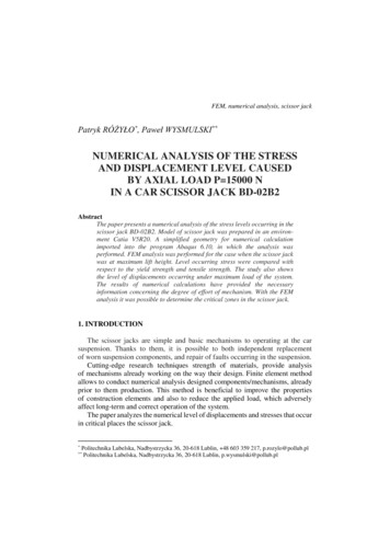
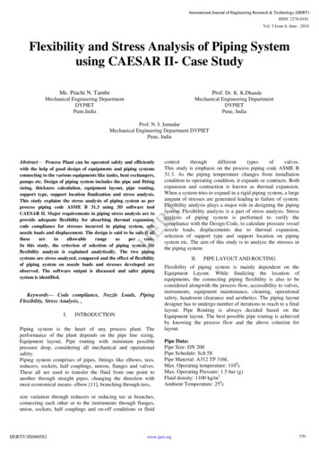
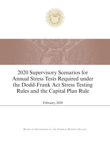
International Journal of Engineering Research & Technology (IJERT)ISSN: 2278-0181Vol. 4 Issue 09, September-2015As the loads I and II are vertical and loads III and IV arehorizontal, they will have different section modulus (W). Thestresses created by the loads in the most critical section are:𝑚𝐼σ𝐼 16.2 [𝑀𝑃𝑎]𝑤𝑥𝑚𝐼𝐼σ𝐼𝐼 408 �� 9 [𝑀𝑃𝑎]𝑤𝑦Stress on the most critical section:σ σ𝐼 σ𝐼𝐼 σ𝐼𝐼𝐼σ 16.2 408 9σ 433.2 [𝑀𝑃𝑎].Stress in Rectangular section beam 140*80 carrying load of1000Kg is 433.2[𝑀𝑃𝑎].Total deformation created due to the loads acting is:IV.ANALYSIS OF BEAM USING ANSYS FEMSOFTWARE:The material considered is structural steel ASTM A36 steel in thiswork, stress analysis of a girder beam of jib crane is done usingANSYS. The model was prepared in CATIA software using allthe geometric parameters given in the standard list, and thenimported to ANSYS. The beam will be simulated, as in the theoryof cranes calculation, beam is fixed at one end and free at anotherend. Own weight due to gravity Vertical service load Meshi.FEM Analysis for Cantilever I-Type Beam, MB150,carrying load -1000Kg𝑃𝐿3𝑊𝐿3𝑦 3𝐸𝐼 8𝐸𝐼y 35.03mmWhere, σ Stress (N/𝑚2 )y Deflection (𝑚𝑚)W Sectional modulus (𝑚3 )𝐼𝑋 Moment of inertia about X-axisQ Load carrying capacity (Kg)L Span of the beam (𝑚)S Sectional area (𝑚2 )𝑞𝑔 Self weight of the beam (N)𝑞ℎ Horizontal load acting on the load (N)Ρ Density of the material (Kg/𝑚3 )P Service load/hoisting load (N)The model was prepared using CATIA software, and imported toANSYS. The beam will be simulated, as in the theory of cranescalculation, beam is fixed at one end and free at another end. Ownweight due to gravity -9.81 [m/s2] is applied in Z direction. Thenthe vertical service load is applied (load of the trolley(accessories) load to lift). As we saw in the theory, we put thisvalue in the end of the beam.P 1000*9.81 20*9.81 10006.2 NMeshing is done using automatic meshing method.Results: Von misses stress and Deformation of the beam:After analyses of the beam section in Ansys, we get the followingdistribution shown in the figures below:Figure no 5: Equivalent (von -misses) stress for MB150 Cantilever Ishaped beamFigure no 4: Model of Cantilever I-Type beam MB150 in Catia (V5R21)and in Ansys (14.5)Figure n0 6:Total deformation for MB150 Cantilever I shaped beamIJERTV4IS090682www.ijert.org(This work is licensed under a Creative Commons Attribution 4.0 International License.)934
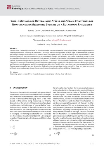
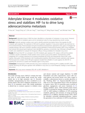
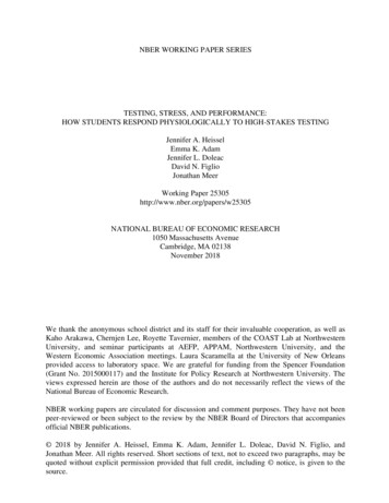
International Journal of Engineering Research & Technology (IJERT)ISSN: 2278-0181Vol. 4 Issue 09, September-2015ii.FEM Analysis for Cantilever Rectangular Section Beam(140*80), carrying load -1000KgFigure no 9:Total deformation for Rectangular section beam.V.RESULTS:The analytical and FEM calculations for four different beamsection were carried out and results are listed in the followingtable. For which it is clear that beam having I shape cross section(MB 150) has developed minimum value of stress and deflection.Hence it is recommended and suggested for the development ofwall mounted jib crane of span 2.5m and having a load carryingcapacity of 1000kg.The analytical and ANSYS results arecompared and the findings shows that results are appropriate withthe error of 0.8% (for MB100) to14.75 % (for MB150) in stress.Figure no 7: Model of Rectangular section beam 140*80 in Catia (V5R21)and imported to Ansys (14.5)Results: Von misses stress and Deformation of the beam:After analyses of the beam section in Ansys, we get the followingdistribution shown in the figures below:Table 3: Comparison of analytical and software analyzed values (stressand deflection)VI.Figure no 8: Equivalent (von -misses) stress for rectangular section beamIJERTV4IS090682CONCLUSION:The analytical and FEM (ANSYS 14.5) results obtained are veryclose. From the static and analytical analysis it is clear that the Isectioned jib crane has got lesser deformation and stressdeveloped which makes it more suited in situations where there isharsh climate. Further the operating life of the jib is alsoimproved. Beam having I shape cross section MB 150 isrecommended for the development of wall mounted jib crane ofspan 2.5m and having a load carrying capacity of 1000kg.As thecomputed stress values in the jib are smaller than the allowablestress of Material (Structural Steel) of the components, thus thejib crane is safe according to I.S norms IS 807:2006 Design,Erection And Testing, Structural Portion of Cranes and Hoists andIS 15419:2004 Jib Cranes- Code Of Practice. The results obtainedfrom FEM analysis show that the boundary conditions have beenchosen correctly. Use of FEM method for structural analysis ofgirder beam of Jib crane is validated which will save considerablecomputing time.www.ijert.org(This work is licensed under a Creative Commons Attribution 4.0 International License.)935
International Journal of Engineering Research & Technology (IJERT)ISSN: 2278-0181Vol. 4 Issue 09, September-2015ACKNOWLEDGMENTThe author would like to thank for the valuable suggestions andguidance rendered by Dr. V Singh, Prof.N.I.Jamadar. And specialthanks to Dr.K.K.Dhande (HOD-Mechanical Engineering) andDr. R.K. Jain (Principal) for their extreme support to completethis 10][11][12][13][14][15][16][17][18]Gerdemeli I, Kurt S, Tasdemir “DESIGN AND ANALYSIS WITHFINITE ELEMENT METHOD OF JIB CRANE” MechanicalEngineering Istanbul Technical University – Turkey.Sunil R. Kewate, Charudatta A. Simpi, D.R. Choudhari and J.H.Atole “Design Analysis of Cantilever I Type Beam for Jib Crane–APractical Problem of Industry” International Journal of AppliedEngineering Research. ISSN, Volume 9, 2014, pp. 115-120.K Suresh Bollimpelli, V Ravi Kumar, “Design and Analysis ofColumn Mounted JIB Crane”, INTERNATIONAL JOURNAL OFRESEARCH IN AERONAUTICAL AND MECHANICALENGINEERING,vol 3 issue 1,2015,page32-52Krunal Gandhare,Vinay Thute, “Design Optimization of Jib CraneBoom Using Evolutionary Algorithm”, International Journal ofScientific Engineering and Research, Volume 3 Issue 4,2014,page 28.Sergio Armán Morles,“Design of overhead bridge crane beam andstrength calculation for load”,Master’s thesis,AGH University ofScience and Technology,spain ,2012Ajinkya Karpe, Sainath Karpe, Ajaykumar Chawrai “VALIDATIONOF USE OF FEM (ANSYS) FOR STRUCTURAL ANALYSIS OFTOWER CRANE JIB AND STATIC AND DYNAMIC ANALYSIS OFTOWER CRANE JIB USING ANSYS” International Journal ofInnovative Research in Advanced Engineering Volume 1, Issue 4,May 2014.P. V. Joshi, S.K.Dhagat , M. D. Gnanavel “Replacement Decision OfBridge Girder Of A Working EOT Crane Based On Fatigue LifeCalculationFuad Hadžikadunić, Nedeljko Vukojević, Senad Huseinović “ANANALYSIS OF JIB CRANE CONSTRUCTIVE SOLUTION INEXPLOATATION” 12th International Research/Expert Conference''Trends in the Development of Machinery and AssociatedTechnology''TMT 2008, Istanbul, Turkey, 26–30 August, 2008.Miralbés R., Castejón L “Design and Optimisation of Crane Jibs forForklift Trucks” World Congress on Engineering, London, U.K, VolII, July 1 - 3, 2009Sandip D. Shinde “Standardization of Jib Crane Design by “F.E.M.Rules” And Parametric Modeling” International Journal of RecentTrends in Engineering, Vol. 1, No. 5, May 2009.Sijo George, Ashwin Chandy Alex “Design and Force Analysis ofCamera Jib Crane” International Journal of Engineering Research& Technology, Vol. 3 Issue 3, March – 2014.Rajpandian R “Design and Analysis of Overhead Crane StructuralColumns” Journal of Electronics and Communication Engineering(IOSR-JECE) e-ISSN: 2278-2834, p-ISSN: 2278-8735 PP 69-75.B. Ünal, I. Gerdemeli, C.E. Imrak “Modelling And Static StressAnalysis of Shipyard Jib Crane With Finite Element Method”University Review Vol. 2, No. 4 Trenčín: Alexander DubčekUniversity of Trenčín2008, 90 p.Rehan H Zuberi, Dr. Long Kai, Prof. ZuoZhengxing, DesignOptimization of EOT Crane Bridge, International Conference onEngineering Optimization, Brazil,2008Indian Standard 15419:2004, Jib Cranes- Code of PracticeIndian Standard 807:2006, Design, Erection and Testing (StructuralPortion) of Cranes and Hoists- Code of Practice.Indian Standard 800:2007, General Construction In steel- Code ofPractice.“Cranes” http://en.wikipedia.org/wiki/Crane.IJERTV4I
most suitable and safe in the working load range of 1000kg.This study aims at stress analysis of single girder wall mounted jib crane of following specification: i. load carrying capacity 1000 kg, ii. span length 2.5 m iii. swing range 180 degrees 140*80 Keywords - Jib crane, FEM (Ansys), Beam, Analytical. I. INTRODUCTIONCited by: 1Page Count: 5File Size: 643KBAuthor: Amreeta Kaigude, V. SinghPeople also search forwall cantilever jib crane