Transcription
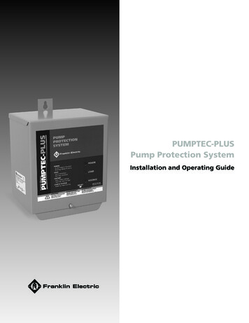
PUMPTEC-PLUSPump Protection SystemInstallation and Operating Guide
Before Getting StartedRead and follow safety instructions. Refer to product data plate(s) for additionaloperating instructions and specifications.This is the safety alert symbol. When you see thissymbol on your pump or in this manual,look for one of the following signal words and be alert to the potential for personal injury:DANGERwarns about hazards that will cause serious personal injury,death or major property damage if ignored.WARNINGwarns about hazards that can cause serious personalinjury, death or major property damage if ignored.CAUTION warns about hazards that will or can cause minor personalinjury or major property damage if ignored.NOTICEindicates special instructions which are imported but notrelated to hazards. Carefully read and follow all safety instructions in this manualand on pump.WARNINGRISK OF ELECTRIC SHOCK - This pump is supplied with a grounding conductor andgrounding type attachment plug. To reduce risk of electric shock, be certain that it isconnected only to a properly grounded, grounding-type receptacle. Disconnect power beforeworking on or around the Inline system. Do not use the Inline system in swimming areas.This equipment should be installed by technically qualified personnel. Failure to installit in compliance with national and local electrical codes and within Franklin Electricrecommendations may result in electrical shock or fire hazard, unsatisfactory performanceor equipment failure. Installation information is available through pump manufacturers anddistributors, or directly from Franklin Electric at our toll-free number 1-800-348-2420.This equipment must not be used by children or persons with reduced physical, sensory ormental abilities, or lacking in experience and expertise, unless supervised or instructed.Children may not use the equipment, nor may they play with the equipment or in theimmediate vicinity.If the power cord is damaged, it must only be replaced by qualified personnel.CAUTION Keep work area clean, well-lit, and uncluttered.Keep safety labels clean and in good condition.Wear safety glasses while installing or performing maintenance on pump.Do not run pump dry. Fill pump with water before starting or pump will be damaged.Make sure all ELECTRICAL POWER IS OFF before connecting any electrical wires. WireInline Pressure Boosting System for correct voltage. Follow all pump wiring instructionsprovided in the "Wiring" section of this manual.
Table of ContentsBefore Getting Started . . . . . . . . . . . . . . . . . . . . . . . . . . . . . . . . . . . . . . . . . . . . . . . 2Features . . . . . . . . . . . . . . . . . . . . . . . . . . . . . . . . . . . . . . . . . . . . . . . . . . . . . . . . . . 4Installation . . . . . . . . . . . . . . . . . . . . . . . . . . . . . . . . . . . . . . . . . . . . . . . . . . . . . . . . 5Operation . . . . . . . . . . . . . . . . . . . . . . . . . . . . . . . . . . . . . . . . . . . . . . . . . . . . . . . . . 8Troubleshooting During Installation . . . . . . . . . . . . . . . . . . . . . . . . . . . . . . . . . . . . 11Troubleshooting After Installation . . . . . . . . . . . . . . . . . . . . . . . . . . . . . . . . . . . . . 12
PUMPTEC-PLUS Pump Protection SystemFeatures Over/Underload Protection Snapshot Calibration Over/Under Voltage Protection Continuous Calibration Memory Rapid Cycle Detection Works With All Single-phase Motors Fault Indicator Lights Transient Surge Protection Run Indicator Light UL Listed (E104778) 5 hp Contactor Adjustable Automatic Restart Timer Heavy-Duty Terminal Blocks Toll-Free Customer Support (800-348-2420)Installation InformationWARNINGTo avoid possible fatal shock, disconnect power at the main power panelbefore installing, wiring or servicing Pumptec-Plus.CAUTIONThis product does not replace a motor control box or the need for motoroverload protection. Installation and motor overload protection should be inaccordance with National Electrical Code Article 430 or in accordance with motormanufacturer’s recommendations.NOTE: This unit requires calibration before operation. Calibration is described in step 7 of theinstallation instructions.Technical SpecificationsHorsepower Rating1/2 to 5 hpOperating Voltage230 VAC*Operating Frequency60 HzPower Consumption5 WattsOperating Termperature Range-15 F to 140 FOver/Under Voltage Trip 10%Over/Underload Trip 25%**Rapid Cycle Trip4 starts/minTrip Response Time2.5 secAutomatic Restart Time1 min to 4hr 15 minOver/Under Voltage Retry2 minCalibration Abort Time3 minCalibration Memory10 yearsContactor Rating5 hp* 220 Volt, 50 Hz for model #5800060500** Percent of load time of calibration SNAPSHOT4
PUMPTEC-PLUS Pump Protection SystemInstallation1. Remove CoverRemove the Pumptec-Plus cover by removing the cover screw and sliding the cover up. Place coverin a safe location.FRONT COVER SCREW2. Set the Timer SwitchSet the automatic timer switch to the desired reset time. This will determine the time after anunderload trip condition (dry well condition) has occurred until the Pumptec-Plus will try to restartthe motor.67 840 15923Notch indicatestimer selectionTimer Switch Settings0) Manual Reset1) 1 Minute2) 2 Minutes3) 4 Minutes4) 8 Minutes5) 16 Minutes6) 32 Minutes7) 1 Hour 4 Minutes8) 2 Hours 8 Minutes9) 4 Hours 16 Minutes5
PUMPTEC-PLUS Pump Protection System3. Mount the UnitMount the Pumptec-Plus unit in a location convenient for wiring. Avoid direct sunlight, rain orsnow.DISCONNECT POWER AT THE MAIN PANEL before installing,WARNING wiring or servicing the Pumptec-Plus unit. Serious or fatal shockmay occur if power is not disconnected.MOUNTING SURFACESCREW4. Connect Power and MotorCheck to make sure the 230 Volt power has been disconnected. Connect Pumptec-Plus unit tothe pump motor and the 230 Volt AC line according to one of the two- or three-wire installationdrawings below. Pumptec-Plus may be wired into the circuit before or after the pressure switch,float switch or other system control switch.2-WIRE INSTALLATIONGND L2L1FUSEDDISCONNECTORCIRCUITBREAKERGND L2L1L1PUMP &MOTORL2M1M2GNDPRESSURESWITCHOR OTHERCONTROLGNDL2L1GND6
PUMPTEC-PLUS Pump Protection System3-WIRE INSTALLATIONPUMP &MOTORGND L2L1FUSEDDISCONNECTORCIRCUITBREAKERGND L2L1L1L2M1M2GNDBLKPRESSURESWITCHOR OTHERCONTROLREDM1GND M2 M1YELCONTROLGNDBOXL1 L2GNDM23-WIRE INSTALLATION WITH DELUXE CONTROL BOXL1L2M1M2GND L2PRESSURESWITCHOR OTHERCONTROLM2 L2L1GNDFUSEDDISCONNECTORCIRCUITBREAKERGND L2SW2 L2PUMP &MOTORREDBLKDELUXECONTROLGNDBOXL1L1L2YELGND5. Replace CoverReplace cover and secure with screw provided.6. Apply PowerOnce power is applied the Pumptec-Plus unit should trip, indicating an overload condition(blinking yellow light) when the pump tries to run. This is normal and is a reminder thatPumptec-Plus requires calibration.NOTE: Some 1/2 hp motors will not trip in an overload condition upon the initial application ofpower. The green light will blink instead. This is also a normal condition. Proceed to step 7.7
PUMPTEC-PLUS Pump Protection System7. CalibrateBefore the Pumptec-Plus unit is ready for use it MUST BE CALIBRATED. The calibrationprocedure is quick and as simple as taking a snapshot.Calibration may be performed as many times as desired by following steps A, B, and Cbelow.A. Press and hold in the reset button on the bottom of the Pumptec-Plus enclosure untilthe green, yellow, and red lights blink alternately. This should take approximately 10seconds. You will hear the Pumptec-Plus contactor engage and the motor shouldstart. Release the reset button. Steps B and C must be completed within threeminutes or the calibration procedure will be aborted.B. Verify that the pump system is running normally (i.e. the system is pumping waterand the motor current is normal). Try to achieve maximum water flow rate. Calibrationon a fully recovered well is recommended.C. Briefly press the reset switch again and then release it. You have just taken asnapshot of the motor load. All indicator lights will go off. After 2 to 3 seconds,the green light will start flashing, indicating the system is running normally andcalibration is complete. Over/underload trips will occur at 125% and 75% of thesnapshot load.NOTE: Continuous memory holds calibration snapshot even if power is absent.CAUTIONPumptec-Plus should only be calibrated by qualified service personnel.Calibration on a faulty pump system will not provide protection.OperationUnder normal operating conditions, Pumptec-Plus requires no special attention. Thepower line voltage and motor power draw are continuously measured. If a fault condition isdetected, an indication is given by a light on the front panel and the motor is disconnectedfrom the power line.Pumptec-Plus measures the actual motor power (Watts), not motor amps or power factor.The motor power draw at the moment of calibration is permanently memorized by PumptecPlus. If the motor power draw differs from the memorized calibration power by more than 25%, Pumptec-Plus will turn off the pump motor. It is very important to make sure the pumpsystem is running normally during the calibration process.There are three indicator lights (A, B, and C) visible through the front cover. Each light is adifferent color and each has a special meaning. Also, on the bottom of the unit enclosureis a reset button (D). The purpose of each light and the operation of the reset button aredescribed on page 5.8
PUMPTEC-PLUS Pump Protection SystemOperation cont.A. GREEN LIGHTB. YELLOW LIGHTC. RED LIGHTD. RESET BUTTONA. Green LightThe green light (A) indicates that the status of the pump system is normal.A SOLID GREEN LIGHT indicates that Pumptec-Plus has power and the contactor to themotor is closed but the motor is not running. This may happen when the pressure switch iswired in down-line from Pumptec-Plus and the switch is open. Pumptec-Plus is waiting forthe pressure switch to close.A FLASHING GREEN LIGHT indicates the pump motor is running normally and drawing thecorrect amount of power.B. Yellow LightThe yellow light (B) indicates that a load fault has occurred.A SOLID YELLOW LIGHT indicates an underload fault occurred. The Pumptec-Plusautomatic restart timer will restart the motor in accordance with the position of theautomatic restart timer switch setting. The switch should be set at the time of installation(refer to step 2). If set in the manual position, Pumptec-Plus must be reset manually bypushing the RESET BUTTON (D).A FLASHING YELLOW LIGHT indicates an overload condition occurred. This means thatthe pump system power draw was greater than the normal operating power (calibration)by more than 25% for more than 2.5 seconds. Pumptec-Plus will not run the pump systemagain until the RESET BUTTON (D) is pressed.9
PUMPTEC-PLUS Pump Protection SystemC. Red LightThe red light (C) indicates a line voltage fault occurred and Pumptec-Plus has turned off the pumpmotor.A SOLID RED LIGHT indicates an under voltage condition (line 207 VAC) existed for more than 2.5seconds. Pumptec-Plus will automatically try to reset the motor within two minutes. The RESETBUTTON (D) may also be pressed to clear this condition.A FLASHING RED LIGHT indicates an over voltage condition (line 253 VAC) has existed more than2.5 seconds. Pumptec-Plus will automatically try to reset the motor within two minutes. The RESETBUTTON (D) may also be pressed to clear this condition.B & C. Red and Yellow Flashing LightsIf the RED and YELLOW lights (B & C) are flashing on and off together, a rapid cycle condition wasdetected. A rapid cycle condition is defined as four or more motor starts per minute.RESET BUTTOND. Reset ButtonThe reset button is used to restart the Pumptec-Plus from a tripped condition. Pressing the resetbutton for less than ten seconds has no effect on the calibration. Simply press and release thebutton. The unit will reset.Pressing the reset button for more than 10 seconds will cause the unit to go into the calibrationmode. A rotating light sequence from green to yellow to red will begin. At this point, the contactorcloses and the motor will start to run. The unit will stay in the calibration mode for 3 minutes oruntil the reset button is pressed again.If after three minutes the reset button is not pressed, the unit will revert back to its normal runningmode, making no changes to the calibration.Pressing the reset button before the three minute period expires will cause the unit to recalibrate tothe motor load present at the time the reset button is pressed the second time.10
PUMPTEC-PLUS Pump Protection SystemTroubleshooting During InstallationSymptomUnit Appears Dead(No Lights)Possible CauseSolutionNo Power to UnitCheck wiring. Power supply voltage should be appliedto the L1 and L2 terminals of the Pumptec-Plus. Insome installations, the pressure switch or othercontrol device is wired to the input of the PumptecPlus. Make sure this switch is closed.Unit Needs to Be CalibratedPumptec-Plus is calibrated at the factory so that it willoverload on most pump systems when the unit is firstinstalled. This overload condition is a reminder thatthe Pumptec-Plus unit requires calibration before use.See step 7 of the installation instructions.Flashing Yellow LightMiscalibratedFlashing Yellow LightDuring CalibrationPumptec-Plus should be calibrated on a fullyrecovered well with maximum water flow. Flowrestrictors are not recommended.Two-Wire MotorStep C of the calibration instructions indicates that aflashing green light condition will occur 2 to 3 secondsafter taking the snapshot of the motor load. On sometwo-wire motors, the yellow light will flash instead ofthe green light. Press and release the reset button.The green should start flashing.Power InterruptorDuring the installation of Pumptec-Plus, power may beswitched on and off several times. If power is cycledmore than four times within a minute, Pumptec-Pluswill trip on rapid cycle. Press and release the resetbutton to restart the unit.Flashing Redand Yellow LightsFloat SwitchHigh Line VoltageA bobbing float switch may cause the unit to detecta rapid cycle condition on any motor or an overloadcondition on two-wire motors. Try to reduce watersplashing or use a different switch.The line voltage is over 253 Volts.Check line voltage.*Unloaded GeneratorIf you are using a generator, the line voltage maybecome too high when the generator unloads.Pumptec-Plus will not allow the motor to turn on againuntil the line voltage returns to normal. Over voltagetrips will also occur if the line frequency drops too farbelow 60 Hz.Low Line VoltageThe line voltage is below 207 Volts. Check line voltage.Flashing Red LightLoose ConnectionsSolid Red LightLoaded GeneratorCheck for loose connections which may causevoltage drops.If you are using a generator, the line voltage maybecome too low when the generator loads. PumptecPlus will trip on under voltage if the generator voltagedrops below 207 Volts for more than 2.5 seconds.Under voltage trips will also occur if the line frequencyrises too far above 60 Hz.*Report high or low line voltage to the power company.11
PUMPTEC-PLUS Pump Protection SystemTroubleshooting After InstallationSymptomPossible CauseSolutionDry WellWait for the automatic restart timer to time out. Duringthe time out period the well should recover and fill withwater. If the automatic reset timer switch is set to themanual position, then the reset button must be pressedto reactivate the unit.Blocked IntakeSolid Yellow LightBlocked DischargeCheck ValveReplace check valve.Replace broken parts.Worn PumpFloat SwitchA bobbing float switch can cause two-wire motorsto stall. Arrange plumbing to avoid splashing water.Replace float switch.Solid Red LightLoose ConnectionsCheck insulation resistance on motor and control boxcable.Step C of the calibration instructions indicates that aflashing green light condition will occur 2 to 3 secondsafter taking the Snapshot of the motor load. On sometwo-wire motors, the yellow light will flash instead ofthe green light. Press and release the reset button. Thegreen should start flashing.Check for excessive voltage drops in the systemelectrical connections (i.e. circuit breakers, fuseclips, pressure switch, and Pumptec-Plus L1 and L2terminals). Repair connections.High Line VoltageThe line voltage is over 253 Volts. Check line voltage.*The Pumptec-Plus will try to restart the motor everytwo minutes until line voltage is normal.Rapid CycleThe most common cause for the rapid cycle conditionis a waterlogged tank. Check for a ruptured bladder inthe water tank. Check the air volume control or sniftervalve for proper operation. Check the setting on thepressure switch and examine for defects.Leaky Well SystemReplace damaged pipes or repair leaks.Stuck Check ValveFailed valve will not hold pressure. Replace valve.Float Switch*Report high or low line voltage to the power company.12Replace worn pump parts and recalibrate.Repair or replace pump motor. Pump may be sand ormud locked.Low Line VoltageFlashing Red AndYellow LightsMachine gun rapid cycling can cause an underloadcondition. See flashing red and yellow lights sectionbelow.Stalled MotorGround FaultFlashing Red LightRemove blockage in plumbing.Broken ShaftSevere Rapid CyclingFlashing Yellow LightClean or replace pump intake screen.Press and release the reset button to restart the unit.A bobbing float switch may cause the unit to detecta rapid cycle condition on any motor or an overloadcondition on two-wire motors. Try to reduce watersplashing or use a different switch.
STANDARD LIMITED WARRANTYExcept as set forth in an Extended Warranty, for twelve (12) months from the date of installation, but in no event more than twenty-four(24) months from the date of manufacture, Franklin hereby warrants to the purchaser (“Purchaser”) of Franklin’s products that, for theapplicable warranty period, the products purchased will (i) be free from defects in workmanship and material at the time of shipment, (ii)perform consistently with samples previously supplied and (iii) conform to the specifications published or agreed to in writing between thepurchaser and Franklin. This limited warranty extends only to products purchased directly from Franklin. If a product is purchased otherthan from a distributor or directly from Franklin, such product must be installed by a Franklin Certified Installer for this limited warranty toapply. This limited warranty is not assignable or transferable to any subsequent purchaser or user.a. THIS LIMITED WARRANTY IS IN LIEU OF ALL OTHER WARRANTIES, WRITTEN OR ORAL, STATUTORY, EXPRESS, OR IMPLIED,INCLUDING ANY WARRANTY OF MERCHANTABILITY OR FITNESS FOR A PARTICULAR PURPOSE. PURCHASER’S SOLE ANDEXCLUSIVE REMEDYFOR FRANKLIN’S BREACH OF ITS OBLIGATIONS HEREUNDER, INCLUDING BREACH OF ANY EXPRESS OR IMPLIED WARRANTY OROTHERWISE, UNLESS PROVIDED ON THE FACE HEREOF OR IN A WRITTEN INSTRUMENT MADE PART OF THIS LIMITED WARRANTY,SHALL BE FOR THE PURCHASE PRICE PAID TO FRANKLIN FOR THE NONCONFORMING OR DEFECTIVE PRODUCT OR FOR THEREPAIR OR REPLACEMENT OF NONCONFORMING OR DEFECTIVE PRODUCT, AT FRANKLIN’S ELECTION. ANY FRANKLIN PRODUCTWHICH FRANKLIN DETERMINES TO BE DEFECTIVE WITHIN THE WARRANTY PERIOD SHALL BE, AT FRANKLIN’S SOLE OPTION,REPAIRED, REPLACED, OR A REFUND OF THE PURCHASE PRICE PAID. Some states do not allow limitations on how long an impliedwarranty lasts, therefore, the limitations and exclusions relating to the products may not apply.b. WITHOUT LIMITING THE GENERALITY OF THE EXCLUSIONS OF THIS LIMITED WARRANTY, FRANKLIN SHALL NOT BE LIABLE TOTHE PURCHASER OR ANY THIRD PARTY FOR ANY AND ALL (i) INCIDENTAL EXPENSES OR OTHER CHARGES, COSTS, EXPENSES(INCLUDING COSTS OF INSPECTION, TESTING, STORAGE, OR TRANSPORTATION) OR (ii) DAMAGES, INCLUDING CONSEQUENTIAL,SPECIAL DAMAGES, PUNITIVE OR INDIRECT DAMAGES, INCLUDING, WITHOUT LIMITATION, LOST PROFITS, LOST TIME ANDLOST BUSINESS OPPORTUNITIES, REGARDLESS
Pumptec-Plus will not run the pump system again until the RESET BUTTON (D) is pressed. A. GREEN LIGHT B. YELLOW LIGHT C. RED LIGHT D. RESET BUTTON. 10 PUMPTC-PU Pump Protection ystem C. Red Light The red light (C) indicates a line v

