Transcription
GUIDELINES FOR PUMP SYSTEM DESIGNERSJacques Chaurette p. eng.www.pumpfundamentals.comAugust 2011SynopsisThe following is a list of potential problems areas or simply just good design practicethat the author has applied and encountered over the years. They deal mainly withpiping issues that affect pump performance.1. Flow and pressure relationship of a pumpWhen the flow increases, the discharge pressure of the pump decreases, and when theflow decreases the discharge pressure increases(ref. http://www.lightmypump.com/tutorial2.htm).2. Do not let a pump run at zero flowDo not let a centrifugal pump operate for long periods of time at zero flow. In residentialsystems, the pressure switch shuts the pump down when the pressure is high whichmeans there is low or no flow.3. Use pressure gaugesMake sure your pump has a pressure gauge on the discharge side close to the outlet ofthe pump this will help you diagnose pump system problems. It is also useful to have apressure gauge on the suction side, the difference in pressure is proportional to the totalhead. The pressure gauge reading will have to be corrected for elevation since thereference plane for total head calculation is the suction flange of the pump.4. Do not let a pump run dry, use a check valveMost centrifugal pumps cannot run dry, ensure that the pump is always full of liquid. Inresidential systems, to ensure that the pump stays full of the liquid use a check valve(also called a foot valve) at the water source end of the suction line. Certain types ofcentrifugal pumps do not require a check valve as they can generate suction at thepump inlet to lift the fluid into the pump, see http://www.watertanks.com/category/43/.These pumps are called jet pumps and are fabricated by many manufacturers Gouldsbeing one of them.Make use of check valves to isolate pumps installed in parallel.
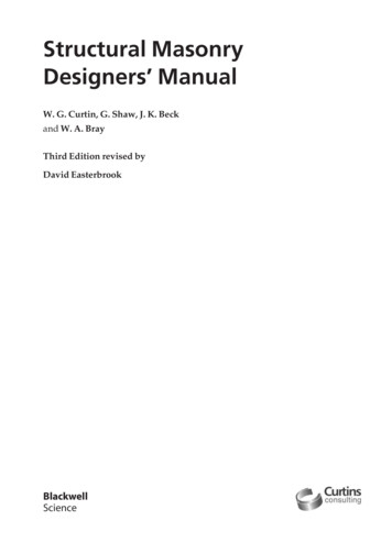
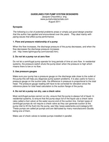
Guidelines for pump system designers 25. Suction valvesGate valves at the pump suction and discharge should be used as these offer noresistance to flow and can provide a tight shut-off. Butterfly valves are often used butthey do provide some resistance and their presence in the flow stream can potentiallybe a source of hang-ups which would be critical at the suction. They do close fasterthan gate valves but are not as leak proof.6. Eccentric reducerAlways use an eccentric reducer at the pump suction when a pipe size transition isrequired. Put the flat on top when the fluid is coming from below or straight (see nextFigure) and the flat on the bottom when the fluid is coming from the top. This will avoidan air pocket at the pump suction and allow air to be evacuated.Figure 1 Eccentric reducers at the pump suction (source: the Pump handbook published byMcGraw-Hill)7. Use a multi-stage turbine pump for deep wellsFor deep wells (200-300 feet) a submersible multi-stage pump is required. They comein different sizes (4" and 6") and fit inside your bore hole pipe. Pumps with differentratings are available, see http://www.webtrol.com/domestic pumps/8in turbine.htm8. Flow controlIf you need to control the flow, use a valve on the discharge side of the pump, never usea valve on the suction side for this purpose.
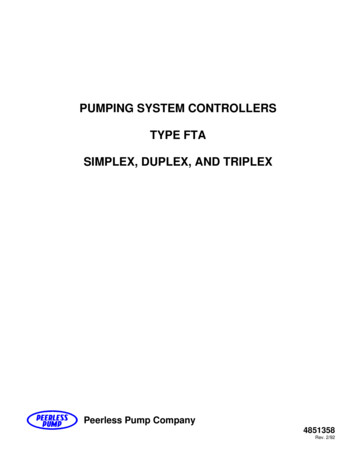
Guidelines for pump system designers 39. Plan ahead for flow metersFor new systems that do not have a flow meter, install flanges that are designed for anorifice plate in a straight part of the pipe (see next Figure) and do not install the orificeplate. In the future, whoever trouble-shoots the pump will have a way to measure flowwithout the owner having to incur major downtime or expense. Note: orifice plates arenot suitable for slurries.Figure 2 Orifice plate (source: www.orificeplates.com)10. Avoid pockets and high pointsAvoid pockets or high point where air can accumulate in the discharge piping. An idealpipe run is one where the piping gradually slopes up from the pump to the outlet. Thiswill ensure that any air in the discharge side of the pump can be evacuated to the outlet.11. Water hammerBe aware of potential water hammer problems. This is particularly serious for largepiping systems such as are installed in municipal water supply distribution systems.These systems are characterized by long gradually upward sloping and then downwardsloping pipes. Solutions to this can involve special pressure/vacuum reducing valves atthe high and low points or additional tanks which provide a buffer for pressure surges(see http://www.ventomat.com/default.asp).see also the pump glossary http://www.lightmypump.com/pump glossary.htm#gl65For pumps 500 gals/min or larger use semi-automatic manual valves at the dischargethat are controlled to open gradually when starting the pump. This will avoid waterhammer during the initial start and damage to the piping system.
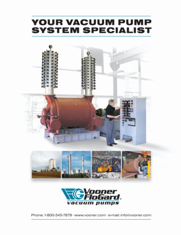
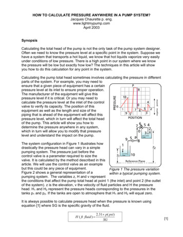
Guidelines for pump system designers 412. The right pipe sizeThe right pipe size is a compromise between cost (bigger pipes are more expensive)and excessive friction loss (small pipes cause high friction loss and will affect the pumpperformance). Generally speaking, the discharge pipe size can be the same size as thepump discharge connection, you can see if this is reasonable by calculating the frictionloss of the whole system. For the suction side, you can also use the same size pipe asthe pump suction connection, often one size bigger is used (ref. tutorial3.htm). A typicalvelocity range used for sizing pipes on the discharge side of the pump is 9-12 ft/s andfor the suction side 3-6 ft/s.13. Pressure at high point of systemCalculate the level of pressure of the high point in your system. The pressure may below enough for the fluid to vaporize and create a vapor pocket which will be detrimentalto the performance of the system. The pressure at this point can be increased byinstalling a valve at some point past the high point and by closing this valve you canadjust the pressure at the high point. Of course, you will need to take that into accountin the total head calculations of the pump.Figure 3 Location of low pressure at a high point inthe system.14. Pump pressure rating and series operationFor series pump installations make sure that the pressure rating of the pumps isadequate. This is particularly critical in the case where the system could become
Guidelines for pump system designers 5plugged due to an obstruction. All the pumps will reach their shut-of head and thepressure produced will be cumulative. The same applies for the pressure rating of thepipes and flanges.Figure 4 Danger of increased pressure due toa plug in a series pump system.15. Inadequate pump suction submersionThere is a minimum height to be respected between the free surface of the pumpsuction tank and the pump suction. If this height is not maintained a vortex will form atthe surface and cause air to be entrained in the pump reducing the pump capacity.see also the pump glossary http://www.lightmypump.com/pump glossary.htm#gl4716. Pump selectionSelect your pump based on total head (not discharge pressure) and flow rate. The flowrate will depend on your maximum requirement. Total head is the amount of energy thatthe pump needs to deliver to account for the elevation difference and friction loss in yoursystem (ref. http://www.lightmypump.com/tutorial3.htm).Pump selection starts with acquiring detail knowledge of the system. If you are justreplacing an existing pump then of course there is no problem. If you are replacing anexisting pump with problems or looking for a pump for a new application then you willneed to know exactly how the systems is intended to work. You should have the P&ID
Guidelines for pump system designers 6diagram and understand the reasons for all the devices included in your system. Youshould make your own sketch of the system that includes all the information on theP&ID plus elevations (max., min., in, out, equipment), path of highest total head, fluidproperties, max. and min. flow rates and anything pertinent to total head calculations.Figure 5 Typical example of flow schematic used for total head calculations.Depending on the industry or plant that you work in, you will be forced to either select acertain type of pump or manufacturer or both. Manufacturers are normally a very goodsource of information for final pump selection and you should always consult with them,do your own selection first and confirm it with the manufacturer. They can help youselect the right type, model, and speed if you have all the operating conditions and if notthey will rarely be able to help you. This form will help you gather all the informationpertinent to operation and selection of your pump.Aside from the normal end suction pump, vertical turbine and submersible pumps, thereis a wide variety of specialized pumps- that you should consider for your application ifyou have unusual conditions.In the selection process, you will be trying to match your flow rate with the B.E.P. of thepump. It is not always possible to match the flow rate with the B.E.P. (best efficiencypoint), if this is not possible, try to remain in the range of 80% to 110% of the B.E.P.
Guidelines for pump system designers 7Figure 6 Desirable selection area for impeller sizefor centrifugal pumps.Operating outside this range will lead to excessive vibration, see the next two figures.Figure 7 is from the Pump Handbook from McGraw-Hill which shows how the axial forceincreases with the distance in terms of percent flow from the B.E.P. Figure 8 fromGoulds essentially shows the same information but in terms of vibration.Figure 7 Radial force vs. % flow of BEP
Guidelines for pump system designers 8Figure 8 Vibration level vs. flow.Electronic pump curves have been created for many (over 50) manufacturers, see a listof them here. They have all been developed by Engineered Software located in LaceyWashington USA of which I am a representative ( see http://www.eng-software.htm).Their pump sizing software PUMP-FLO can help find the best pump for the application,it can select the closest one to the B.E.P. for you and do all kinds of searches based onNPSHR, efficiency, size, etc.When you order your pump make sure that the motor is installed with spacer blocks sothat the next largest motor frame can be installed.17. Effect of viscosity on pump performanceViscosity is the main criteria which determines whether the application requires acentrifugal pump or a positive displacement pump. Centrifugal pumps can pump viscousfluids however the performance is adversely affected. If your fluid is over 400 cSt(centiStokes) in viscosity consider using a positive displacement pump.see also the pump glossary http://www.lightmypump.com/pump glossary.htm#gl6318. Avoid running pump in reverse directionAvoid running a pump in reverse direction, pump shafts have been broken this wayespecially if the pump is started while running backwards. The simplest solution is toinstall a check valve on the discharge line.
Guidelines for pump system designers 919. Minimum flow rateMost centrifugal pumps should not be used at a flow rate less than 50% of the B.E.P.(best efficiency point) flow rate without a recirculation line. (What is the B.E.P.?) If yoursystem requires a flow rate of 50% or less then use a recirculation line to increase theflow through the pump keeping the flow low in the system, or install a variable speeddrive.How is the minimum flow of a centrifugal pump established (answer from the HydraulicInstitute http://www.pumps.org/public/pump resources/faq.htm)The factors which determine minimum allowable rate of flow include the following:* Temperature rise of the liquid -- This is usually established as 15 F and results in avery low limit. However, if a pump operates at shut off, it could overheat badly.* Radial hydraulic thrust on impellers -- This is most serious with single volute pumpsand, even at flow rates as high as 50% of BEP could cause reduced bearing life,excessive shaft deflection, seal failures, impeller rubbing and shaft breakage.* Flow re-circulation in the pump impeller -- This can also occur below 50% of BEPcausing noise, vibration, cavitation and mechanical damage.* Total head characteristic curve - Some pump curves droop toward shut off, and someVTP curves show a dip in the curve. Operation in such regions should be avoided.There is no standard which establishes precise limits for minimum flow in pumps, but"ANSI/HI 9.6.3-1997 Centrifugal and Vertical Pumps - Allowable Operating Region"discusses all of the factors involved and provides recommendations for the "PreferredOperating Region".20. Three important point on the pump characteristic curveThe performance or characteristic curve of the pump provides information on therelationship between total head and flow rate. There are three important points on thiscurve.
Guidelines for pump system designers 10Figure 9 Location of three important points on thepump characteristic curve.1. The shut-off head, this is the maximum head that the pump can achieve and occursat zero flow. The pump will be noisy and vibrate excessively at this point. The pump willconsume the least amount of power at this point.2. The best efficiency point B.E.P. this is the point at which the pump is the mostefficient and operates with the least vibration and noise. This is often the point for whichpumpxs are rated and which is indicated on the nameplate. The pump will consume thepower corresponding to its B.E.P. rating at this point.3. The maximum flow point, the pump may not operate past this point. The pump will benoisy and vibrate excessively at this point. The pump will consume the maximumamount of power at this point.Sometimes the characteristic curve will include a power consumption curve. This curveis only valid for water, if the fluid has a different density than water you cannot use thiscurve. However you can use the total head vs. flow rate curve since this is independentof density.
Guidelines for pump system designers 11Figure 10 Typical centrifugal pump ch
Their pump sizing software PUMP-FLO can help find the best pump for the application, it can select the closest one to the B.E.P. for you and do all kinds of searches based on NPSHR, efficiency, size, etc. When you order your pump make sure that the motor is installed with spacer blocks so that the next largest motor frame can be installed. 17. Effect of viscosity on pump performance Viscosity .