Transcription
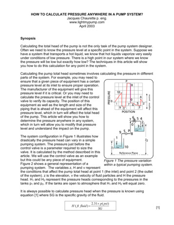
HOW TO CALCULATE PRESSURE ANYWHERE IN A PUMP SYSTEM?Jacques Chaurette p. eng.www.lightmypump.comApril 2003SynopsisCalculating the total head of the pump is not the only task of the pump system designer.Often we need to know the pressure level at a specific point in the system. Suppose wehave a system that transports a hot liquid, we know that hot liquids vaporize very easilyunder conditions of low pressure. There is a high point in our system where we knowthe pressure will be low but exactly how low? The techniques in this article will showyou how to do this calculation for any point in the system.Calculating the pump total head sometimes involves calculating the pressure in differentparts of the system. For example, you may need toensure that a given piece of equipment has a certainpressure level at its inlet to ensure proper operation.The manufacturer of the equipment will give thispressure level if it is critical. Or you may need tocalculate the pressure level at the inlet of the controlvalve to verify its capacity. The position of thisequipment as well as the length and size of thepiping that is ahead of the equipment will affect thispressure level, which in turn will affect the total headof the pump. This article will show you how todetermine the pressure anywhere in any system,which in turn will allow you to modify that pressurelevel and understand the impact on the pump.The system configuration in Figure 1 illustrates howdrastically the pressure head can vary in a simplepumping system. The pressure just before thecontrol valve is a parameter required to size thevalve. It is calculated by the method described in thisarticle. We will use the control valve as an examplebut this could be any piece of equipment.Figure 1 The pressure variationFigure 2 shows a general representation of awithin a typical pumping system.pumping system. The variables z, H and v representthe conditions that affect the pump total head at point 1 (the inlet) and point 2 (the outletof the system). z is the elevation, v the velocity of fluid particles and H the pressurehead. H1 and H2 represent the pressure heads corresponding to the pressures in thetanks p1 and p2. If the tanks are open to atmosphere that H1 and H2 will equal zero.It is always possible to calculate pressure head when the pressure is known usingequation [1] where SG is the specific gravity of the fluid.H ( ft fluid ) 2.31 p ( psi )SG[1]
How to calculate pressure anywhere 2Figure 2 A general representation of a pumpingsystem.HOW TO CALCULATE THE PUMP TOTAL HEAD FROM THE ENERGY BALANCEAn energy balance can determine the total head of the pump or the energy requiredof the pump. The amount of energy that the pump must supply will be the differencein energy between the energies available at points 1 and 2 plus the piping andequipment friction loss in the system at the required flow rate. A very detailexplanation of this is available in a book called “Pump System Analysis andCentrifugal Pump Sizing” by Jacques Chaurette and is available on the web siteshttp://www.lightmypump.com/pump book.htmm.The energy balance is:( p F 1 2 p EQ 1 2 ) p P( p1 p 2 )1 ( v 2 v 2 2 ) ( z1 z 2 )ggg2g 1ρρρgcgcgcEquation [2] is Bernoulli’s equation with the pump pressure increase ( pP) and fluidfriction loss due to piping ( pF1-2) and equipment ( pEQ1-2) friction terms added.Pressure can be expressed in terms of fluid column height or pressure head.ρgHp gcAll pressure terms in equation [2] are replaced by their corresponding fluid columnheights, with the use of equation [3]ρgH1ρg H F 1 2p1 , pF 1 2 , etc.). The constant (gc) cancels out.gcgcThe total head of the pump is:[2][3]
How to calculate pressure anywhere 3 H P ( ft fluid ) ( H F 1 2 H EQ1 2 ) 122(v 2 v1 ) z 2 H 2 ( z1 H 1 )2g[4]The unit of total head ( HP) is feet of fluid in the Imperial system and meters of fluidin the metric system. (See the variable nomenclature table at the end of the articlefor the meaning of the variables in this article)CALCULATE THE PRESSURE HEAD ANYWHERE ON THE DISCHARGE SIDE OFTHE PUMPEquation [4] is the result of an energy balance between points 1 and 2. The sameprocess of making an energy balance can be applied between any two points forexample points 1 and X (see Figure 3). We can do an energy balance between points 1and point X and since we know the value of the total head HP we can calculate theconditions at point X.First, calculate the total head for the complete system using equation [4]. Next, acontrol volume (CONTROL VOLUME 1) is positioned to intersect point X and point 1(see Figure 3). Point X can be located anywhere between P and 2. The systemequation (equation [4]) can be used with point X as the outlet instead of point 2. It isthen resolved for the unknown variable Hx instead of HP.Figure 3 The control volume determines where the conditions on thedischarge side of the pump can be calculated.
How to calculate pressure anywhere 4Equation [4] gives the total head for the complete system and is repeated here: HP ( HF1 2 HEQ1 2) 1 2 2(v v ) (z2 H2 (z1 H1)2g 2 1Equation [4] is applied with the following changes: all terms with subscript 2 arereplaced with the subscript X, H2 HX, HF1-2 HF1-X , HEQ1-2 HEQ1-X, v2 vX, z2 zX. The unknown term Hx is isolated on one side of the equation and we obtainequation [5].HX HP ( HF1 X HEQ1 X ) 1 2(v1 vX 2 ) (z1 H1 zX )2g[5]The unknown pressure head (Hx) can also be determined by using that part of thesystem defined by control volume 2 (see Figure 3) by using the same reasoning asabove, in equation [4], HP 0 and all terms with subscripts 1 replaced with X.Therefore, H1 HX, HF1-2 HFX-2 , HEQ1-2 HEQX-2, v1 vX, z1 zX The unknownterm Hx is isolated on one side of the equation and we obtain equation [6].H X ( HFX 2 HEQX 2 ) 1(v2 2 v X 2 ) (z2 H2 z X )2g[6]We now have two methods for determining the pressure head at any location. Wecan use one equation to verify the results of the other. The calculation of HX is oftenquicker when using equation [6].Note that in equation [6] the value of HP is not required to calculate Hx.CALCULATE THE PRESSURE HEAD ANYWHERE ON THE SUCTION SIDE OFTHE PUMPWe can determine the pressure head anywhere on the suction side of the pump bythe same method. In this case, HP 0 since there is no pump within the controlvolume (see Figure 4). HP 0 and subscript 2 is replaced with subscript X inequation [4]. The unknown term Hx is isolated on one side of the equation and weobtain equation [7].22H X ( H F1 X H EQ1 X ) 1 (v1 vX ) (z1 H1 z X )2gThe velocity (vX) must be the same as the one at point X in the complete system.Equation [6] is important in calculating the N.P.S.H. available and avoidingcavitation. You can find an article that treats this subject specifically wnload12.[7]
How to calculate pressure anywhere 5Figure 4 The control volume determines where the conditionson the suction side of the pump can be calculated.Let’s do a practical example, suppose you have a piece of equipment that requires 30psig pressure at its inlet to function properly. This has happened to me, the equipmentwas a Voith Turbo-Cleaner and Voith specified that the cleaner needed 30 psigpressure at its inlet. The system is shown in Figure 5.Figure 5 A system that requires a specified pressure at the inlet of anequipment.I calculated the total head of the pump using equation [4] without taking into account theinlet pressure requirement of the cleaner and obtained a value of 70 feet of fluid. Youwill have to take my word for this, as you do not have enough information to do thecalculation, for example you are missing the pressure drop across the cleaner, theproperties of the fluid, etc.
How to calculate pressure anywhere 6Using equation [5], I calculated the pressure head at the inlet of the cleaner (point 3) tobe 40 feet that corresponds to 17 psig. This is clearly smaller than required by themanufacturer. There are several options to correct this, the main ones are:1. If the system is in the design stage, reposition the cleaner to increase thepressure at the inlet. If this is impractical then2. Close the manual valve B (see Figure 5) at the outlet of the cleaner (point 4) toincrease the pressure at the inlet (point 3).You cannot close the valve on an existing system that has not been designed for theadditional pressure required at the cleaner inlet. To do so would reduce the flow andthat is not acceptable. You must deal with this during the initial stages of design or if theinstallation is already in operation modify the pump.The pressure required (30 psig) at the cleaner inlet corresponds to (use equation [1]) 69feet of pressure head. Prior to applying this requirement, I calculated that the pressurehead at point 3 was 40 feet, we are missing 29 feet. We must now calculate the totalhead of the pump that will produce the value of 69 feet at point 3 at the flow raterequired. Using equation [5] and with the value of HX (69 feet), we can then calculatethe value of HP, the total head of the pump, which will satisfy the requirements.
How to calculate pressure anywhere 7SymbolsVariable nomenclatureImperial system(FPS units)Metric system(SI units)H HP HEQ HFpheadTotal Headequipment friction head lossfriction head loss in pipespressurem (meter)m (meter)m (meter)m (meter)kPa (kiloPascal)SGspecific gravity; ratio of the fluid densityto the density of water at standardconditionsft (feet)ft (feet)ft (feet)ft (feet)psi (pound per squareinch)non-dimensionalvzvelocityvertical positionft/s (feet/second)ft (feet)m/s (metre/second)m (meter)
Calculating the pump total head sometimes involves calculating the pressure in different parts of the system. For example, you may need to ensure that a given piece of equipment has a certain pressure level at its inlet to ensure proper operation. The manufacturer of the equipment will give this pressure level if it is critical. Or you may need to calculate the pressure level at the inlet of .