Transcription
B r o c h u r e # 07 1 0TYP ET Y P E S E WAG E E JECTOR SYSTE M.VSAFFlows to 600 gpm, Heads to 120’, 1 thru 40HP. Discharge size 4”, 1750 and 1150 RPM,strainer in discharge pipe.HI GHLI GHT S Installations where rags can clogstandard sewage pumps 1750 RPM 1150 RPM Operation Fiberglass or Steel Basins Basket Strainer Traps Large Objects Ideal for Hospitals, Schools, andCorrectional Facilities Control Systems Available
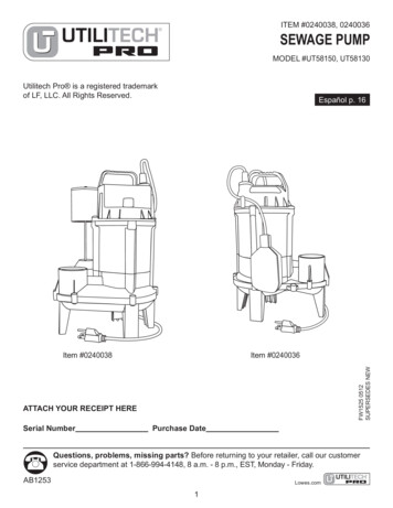
F E AT U R E SFLEXIBLE cOUPLING: Machined and balanced.TH RUST B E ARIN G : B all bearing mounted abovesuspension plate in dust-proof and moisture-proofhousing.ADJUSTING NUTS: Two bronze lock nuts for accuratevertical adjustment of impeller clearance.SUSPENSION PLATE: Cast iron suspension plate hasintegral strengthening ribs.D I Sc H A RG E P I P E : Wro ught ste e l , lo cke d tosuspension plate, held in bottom elbow by slip-boltmating flange.TOP DIScHARGE ELBOW: Cast iron 45 degree elbowwith integral 125 # companion flange. B ot tom ofhousing encloses top expansion joint.STRAINER: Cast iron housing; stainless steel basketeasily removable from top. Entire assembly slips outof discharge line without disturbing piping.OVERFLOW FIT TING: Permits water to over flowdirectly into basin if both pumps are operating.IMPELLER: One-piece cast iron non-clog, dynamicallyand hyraulically balanced, keyed and locked to shaft.Bronze impellers optional.SHAFT: Carbon steel, turned, ground, and polished;sized for maximum load.SUSPENSION LEGS: Cast iron sections with integralend flanges.INTERMEDIATE GUIDE BEARINGS: For each fourfeet of shaft length; renewable bronze sleeve type.cASING: Cast iron with smooth water passages.LOWER DIScHARGE ELBOW: Removable; acts aselbow and housing for bottom expansion joint.BOTTOM GUIDE BEARING: Renewable bronze sleevebearing pressed into casing.LUBRIcATION SySTEM: Guide bearings lubricatedINLET TEE: Cast iron tee with three matingflangesInstallationDiagramthrough flexible grease line. Alemite fitting furnishedfor simple assembly.on the suspension plate for each line. Sight-feed andcONTROL VALVE: Cast iron housing with removableautomatic oilers available.top for easy access; brass flapper. Prevents backingup into house line during discharge cycle. Shut-offhandle cuts off either pump.GATE VALVEEJECTOR DISCHARGE TODISPOSAL SYSTEMCOMMON INLET LINEFROM ALL SOURCESINCLUDING:FLOAT SWITCHHIGH ATER ALARMVENTMANHOLE COVERFLOAT SWITCHELEVATIONPLAN WATER CLOSETSBATH TUBSLAVATORIESSHOWER HEADSURINALSLAUNDRIESSLOP SINKSSERVICE SINKSRESTAURANT SINKSDRINKING FOUNTAINSAREA AND FLOOR DRAINSGROUND WATERWASH RACKS (CARS ETC.)INDUSTRIAL WASTEBOILER PIS& MANY OTHER USESDescriptive DiagramOther Fed-Flush ArrangementsVSAF unit numbers cover ver tical submergeds e w a g e e j e c to r s ( V S A) w i t h F e d - F l u s hf it tings . Fe d - Flush f it tings c an also b ef u rnish e d with VS S su b m e rsib le sewa g ee je c to r s ( VS S F u n it s). S e e su p p lim e nta lpamphlet for pump data. Fed-Flush f it tingscan also be furnished with VSABM dry pitsewage pumps (VSAFBM units).VSSF2VSAFBM
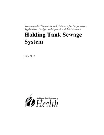
Descriptive DiagramSUGGESTED SPECIFICATIONSFurnish a pedestal mounted alternating float switch, with brassrod and copper float, to provide alternate cycles of operation,plus simultaneous operation when required. Furnish a pedestalmounted auxiliary float switch with brass rod and copper float,for emergency 2-pump operation. Float control equal to FederalType FS-4.Furnish a compression tube type high water alarm actuating switchwith adjustable sensing tube and integral alarm horn, equal toFederal Type FS-5.Furnish each motor with a magnetic line voltage starter providingoverload and low voltage protection, in NEMA-1 wall mountingenclosure, having “Hand-Off-Automatic” selector switch and resetbutton.AFurnish a cast iron (or steel) sewage basin, diameter bydeep, having internal rust resistant coating. Inlet connectionshall be as required by job conditions. Cover shall be steel withall required openings, including those for pumps, controls, alarmactuator, vent conneciton, and manhole. Manhole opening providedwith cast iron cover.EBA LT E R N AT E FO R C O N C R E T E P I T: (s u bs tit u te th e fo l l owi n gparagraph for the above cast iron basin paragraph)Furnish a Federal PF-1 type angle iron pit frame for a concretepit x x deep. Pit to be constructed by generalcontractor. Plumbing contractor shall furnish the pit frame togetherwith a heavy steel pit cover having all required openings, includingthose for pumps, controls, alarm actuator, vent connection andmanhole. Manhole opening provided with cast iron cover. Coverand frame to be treated with a corrosion resistant coating and tobe of castight bolted construction.Note: Inlet adaptor for mounting FED - FLUSH fittings must beinstalled when concrete pit is poured. (Advise inlet size and pitwall thickness when ordering adaptor.)CIN-FLOW cycLESewage water with solids enter fromh o u s e li n e (A). S o li d s a re h e l d i n s tr a i n e r( B ) a n d w aDescriptivet e r c o n t Diagrami n u e s i n t o b a s i n (C ) .SUGGESTED SPECIFICATIONSFurnish and install where shown on plans, Fed-Flush Type VSAF , duplex, vertical, submerged strainer basket type sewageejector unit as manufactured by Federal Pump Corporation. Eachpump to be rated at G.P.M. against a total dynamic head offeet. Pumps to have inch discharge and be constructedfor basin feet deep.The unit shall be so designed that sewage entering the pit shall becarried to the strainer baskets installed in pump discharge lines.Solids will be retained in the baskets and liquids will continuethru the casing into the basin. The strainer shall have a cast ironhousing and a stainless steel basket, removable from the top ofthe housing. Solids shall be flushed into the discharge line duringthe discharge cycle. A control valve shall prevent back-up into thehouse line during discharge cycles and permit cut-off of eitherpump. Overflow fitting shall allow liquid to flow directly into basinduring discharge cycles.Pump shaft shall be large diameter carbon steel; impeller to becast iron, non-clog type; thrust bearing enclosed in moistureproof housing, mounted above the suspension plate. Suspensionplate shall be cast iron; suspension column shall be constructedof cast iron sections, with integral rabbetted end flanges. Bronzeintermediate guide bearings shall be furnished for every four feetof shaft length. Cast iron pump casing shall have pressed-fit bronzebearing. Lubrication of guide bearings shall be by means of alemitegrease fittings on suspension plate and flexible grease lines. Casingshall have bolt-on discharge elbow forming lower expansion jointhousing. Discharge pipe to terminate above the suspension platein a cast iron 45 degree elbow and top expansion joint housing,with 125# ASA integral flange.Motors to be H.P., R.P.M., ph., cy.,volts, vertical, open, drip proof, ball bearing.3DEBCDIScHARGE cycLEWater is pumped from basin (C), flushes solids instrainer (B) out into discharge line (D). Controlvalve (E) prevents backup into house line.
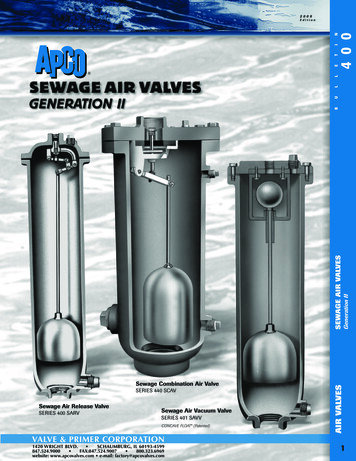
Descriptive DiagramPIT & BASIN COVERSDuplex UnitRound Pit or BasinSQUARE PIT SIZEGcTcOSPF42X4213-34414248-18ROUND PITOR BASINGBOLTcIRcLEBccOVERDIA. 34757866X66mer).nolDuplex UnitSquare 13-34VSAF-4C16-12VSAF-4E16-12Float ControlsCONTROL EQUIPMENTFS-1FS-2FS-3FS-4FS-5FS-6PUMP cONTROLSMOTOR cONTROLSThe following control arrangements are available:The following control arrangements are available:FS-1 (for single unit) one float switch for start-stop control.For single or duplex units: (1) magnetic starter for eachmotor to be mounted on an adjacent wall or on the floatswitch pedestal(s).FS -2 (for duplex unit) two float switches for start-stopcontrol. The switches can be manually set to changethe lead pump. Both pumps will operate if the in-flowrate requires.FS-3 (for duplex unit) - one altemating float switch whichoperates the two pumps on an alternating basis and turnson both pumps simultaneously if the in-flow rate requires.FS-4 (for duplex unit) - one altemating float switch (asdescribed immediately above) plus two-pole emergencyauxiliary float switch which will tum on both pumps ata predetermined high water level if the alternating floatswitch fails to operate for some reason.FS-5 (for single or duplex unit) - a compression tube typehigh water alarm actuating switch with integral alarmhorn. Can also provide signal for remote alarm indication.Alarm panel with bell, indicating light and silencing buttonis also available.FS- 6 (for single or duplex unit) - one float switch to actas a high water alarm actuator instead of the compressiontube type described immediately above.For d uplex unit s: A Typ e D D uplex C ontrol Pan el ina single enclosure for mounting on an adjacent wall.These panels are available as follows:D1000: (2) magnetic starters in one enclosure.D1100: (2) magnetic starters and (2) unfused disconnectswitches in one enclosure.D1200: (2) magnetic starters and (2) fusible disconnectswitches in one enclosure.D1300: (2) magnetic starters and (2) circuit breakers inone enclosure.Modifications are available for magnetic star ters andType D D uplex Panels as follows: special enclosures ,‘ H and - of f-Automatic’ sele ctor switches , pilot light s ,control circuit transformers, manual transfer switch andautomatic pump alternator.4?
Selection Table – 1150 R.P.M.Unit No.5G.P.M.Disch.Head(ft.)PUMP SIZING DATASelection Table – 1150 R.P.M.MotorH.P.Disch.Size(ins.)Unit E-5-65048541.54VSAF-4E-7.5-650617.5432PUMP CAPACIT YPump capacity can be determined by thenumber of water closets to be handled.Other fixtures need not be considered.T h e c a p a c i t y s h ow n a p p l i e s to s i n g l epumps and to each pump of a duplex set.NO. OF WATERcLOSETS HANDLEDPUMP cAPAcITy(G.P.M.)1502 or 3754 or 814VSAF-4F-3-4754334VSAF-4A-1-67523146 or 7125615475261.5415075VSAF-4A-1.5-68 to 10VSAF-4A-5-411 to 15200VSAF-4F-1-41002314VSAF-4A-2-675292416 to 20250VSAF-4F-1.5-4100301.54VSAF-4C-3-675353421 to 25300VSAF-4F-2-41003524VSAF-4E-5-675465426 to VSAF-4F-1-4200714VSAF-4E-5-61254254EX 4P R O P O S E D I N S TA L L AT I O N : S e w a g e b a s i n5 & #3 9 ; - 0 ” i n d e p t h to b e s e t i n g ro u n d , w i t hto p f lush with f urnish e d f lo o r. B ase m e nt f lo o r1 0 & #3 9 ; - 0 ” b e l ow h i g h e s t p o i n t o f d i s c h a rg el i n e . E j e c t o r c a p a c i t y 1 0 0 G . P. M . s i z e o fdischarge lin e 4”VSAF-4A-1.5-425081.54VSAF-4E-5-61504054Static on Head2 f t.VSAF-4A-3-42502534VSAF-4A-1.5-6200161.54Valves & other Fittings3 f t.VSAF-4A-5-42504454VSAF-4A-2-62002224Back 5-630031VSAF-4E-7.5-6300VSAF-4E-10-6If outside drainage is greater than 1/2 thepump capacity as determined above, addthe excess amount to the pump capacity.PUMP DISCHARGE HEADThe discharge head for a sewage ejectorinstallation consists of the following elements:STATIc HEAD: The difference in elevation betweenthe lowest water level in the sewage basin or pit,and the maximum height of the discharge line.FR I c TI O N : Loss of h e a d in th e disch a rg e lin e ,including valves and other fittings.BAcK PRESSURE: Proper allowance must be madefor back pressure in sewer line, if existing.14 f t*.6 f t.Total Dynamic Head25 f t.*Lowest water level estimated to be approximately1 f t. above bottom of sewage basin .DRAINAGE FROM FIXTURES &OTHER SOURCESWater Closet7 G.P.M.4Urinal3 G.P.M.4Lavatory5 G.P.M.4Bath Tub6 G.P.M.34Shower Bath8 G.P.M.54Laundry Tray3 63501324VSAF-4C-3-63502134VSAF-4C-5-63502854Wash Sink or Fountain IndustrialAverageVSAF-4E-7.5-6350427.54Automatic Dishwasher Residential3 G.P.M.VSAF-4E-10-6350501044Service Sink4 024541/2 ” Horse 54Floor DrainVSAF-4E-25-450088254VSAF-4E-10-640044104Auto Wash RackVSAF-4E-30-4500102304VSAF-4E-15-6
line. Ejector capacity 100 G.P.M. size of discharge line 4” Static Head 14 f t*. Friction Head 2 ft. Valves & other Fittings 3 ft. Back Pressure 6 ft. Total Dynamic Head 25 ft. *Lowest water level estimated to be approximately 1 f t. above bottom of sewage basin. DRAINAGE FROM FIXTURES & OTHER SOURCES Water Closet 7 G.P.M. Urinal 3 G.P.M. Lavatory 5 G.P.M.