Transcription
ERATURE TO300412MTECHNICAL MANUALT8 9 106 7TYPE L COPPER TUBEPIGPM FLOW0250IRON PIPEP INGFRICPTION LOS S IT.ER100200015001009080060050040030080706050System Syzer CalculatorInstruction Book403020
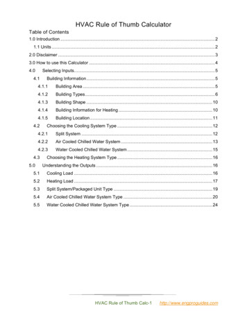
TABLE OF CONTENTSIntroduction.1Scale #1 - Load-GPM Relationships.1Scale #2 – Flow-Pressure Drop Relationships and Pipe Sizing.2Scale #3 – Water Velocity Considerstions.2Scale #4 – Circuit Piping Pressure Drop.3Scale #5 – Determining Unknown Pressure Drops, System Curves and Control Valve Cv ratings.4NOTE:Pump curves and other product data in this bulletin are for illustration only. See Bell & Gossett product literature for moredetailed, up to date information. Other training publications as well as the Bell & Gossett design tools described in thisbooklet including the System Syzer, analog and digital versions, and ESP Plus are all available from your local Bell & Gossettrepresentative. Visit www.bellgossett.com for more information or contact your Bell & Gossett representative.2
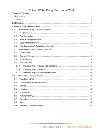
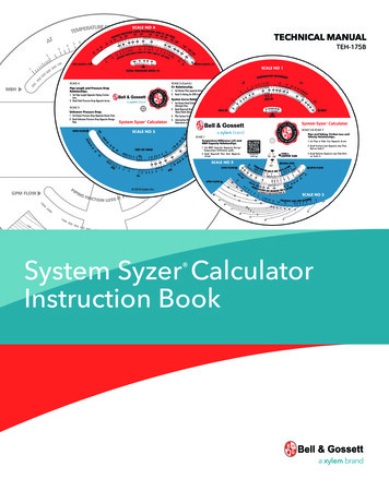
IntroductionExample #2: Determine required GPM flow rate for a coolingload of 20 tons at a 10º temperature rise. At 12,000 Btu perton, a 20 ton load is equivalent to 240,000 Btu per hour or240 MBH.Set 240 MBH opposite 10º temperature difference and read48 GPM on the GPM scale.Design Temperature Difference: For many years, mosthot water systems have been designed for a 20º temperaturedrop. Basically, this has been done because at a 20ºtemperature drop, each GPM circulated conveys 10,000 Btu/Hr. This allows simple determination of flow rates by use ofthe following formula:GPM Btu/Hr.10,000While the 20º design temperature drop is still valid for thesmall hydronic system, it is not necessarily best for the largerengineered system. Higher temperature drops permit lowerflow rates, smaller pipe and pump sizes and in general returneconomic benefits.Scale #1 of the System Syzer Calculator will assist thehydronic designer in establishing minimum flow – maximumtemperature difference system design through the variousdesign approaches now available. These include primarysecondary pumping, coil re-circuiting, terminal unit flowevaluation, etc. Because of the simplicity of determining flowrates for various temperature differences, the System SyzerCalculator will aid greatly in the design of higher temperaturedifference systems.The determination of design data for Hydronic Systems isrelatively simple. Often, however, an engineer must consultseveral different design tables, charts, and formulae toestablish GPM flow requirements, pipe size, pipe pressuredrops, relative water velocities, pumping heads, systemcurves, control valve Cv ratings, etc. The B&G System SyzerCalculator consolidates all necessary design information in asimple, easy to use circular slide rule.The System Syzer Calculator is useful both in final designwork and in preliminary system planning. Proposed pumpand pipe sizes can be quickly roughed out for estimatingpurposes.The System Syzer Calculator has five scales sequenced in thesame way in which they would typically be used in designinga Hydronic System. The following states the reference baseof the various scales and illustrates their uses with designexamples.Scale #1 – Load / GPM RelationshipsScale #1 is stated in terms of temperature difference, MBHand GPM. These terms are defined as follows:A. Temperature difference is the temperature drop (heating)or temperature rise (cooling) taken by the water as it flowsthrough the system.B. MBH is a statement of heating or cooling load inBtu per hour where 1 MBH 1000 Btu per hour;10 MBH 10,000 Btu per hour; 1000 MBH 1,000,000 Btu per hour or 1M as indicated on scale #1.C. GPM is the circulation rate in gallons per minute requiredto convey the design Btu load at design temperaturedifference.GPM flow rate, temperature difference and MBH load arerelated by the following formula:Heat conveyed in Btu/Hr Fluid Flow in lbs/hr x temp. diff.or:Btu/Hr GPM x lb. x Sp.Ht. x 60 min. x ΔTgal.hr.GPM Example #3: Determine primary to secondary flow rate for asecondary zone using a heat injection pump as illustrated inFigure 1.Btu/Hr.lb/gal x Sp.Ht. x 60 min/hr x ΔTScale #1 has been established using a specific heat equal toone and considering water density at 8 1/3 lbs. per gallon(60ºF conditions). These values have been employed inhydronic system design since its inception. For 200ºF water,the rate of heat conveyance decreases slightly (on the orderof 2%) because of reductions in the density and specific heat.This is not normally taken into account, however.Figure 1Example #1: Determine required GPM flow rate for a load of150,000 Btu per hour at a temperature drop of 30º.Set the 150 MBH capacity in the large window under the 30ºdesign ΔT. Read GPM flow rate in the small window oppositethe arrow: 10 GPM.1
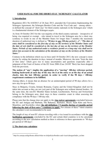
The secondary zone requirements are for 10 GPM of 190ºwater at a 20º ΔT to provide the zone requirements of100,000 Btu. 240º water is available at the primary supplymain. At design load conditions, the required quantity of240º water must flow from point A to point B. An equalquantity of 170º water must flow from point C to point D.The temperature difference between point A and point of 70º(240º-170º) and the 100,000 Btu required for the secondaryzone determine the flow required frown the primary to thesecondary.On scale # 1 of the System Syzer Calculator, set 70ºtemperature difference opposite 100 MBH. Read the requiredprimary to secondary flow rate: 2.9 GPM. The heat injectionpump should be sized to deliver 2.9 GPM against a headdetermined by circuit A-B-C-D.B. Feet per 100 feet establishes the rate of pipe friction lossas being foot head of energy loss per I 00 feet of pipe.The pipe friction loss data used as a basis for constructionof scale #2 are The Hydraulic Institute Values, The ASHRAEGiesecke Chart Values and The ASHRAE Unified PressureDrop Chart data. Both the Hydraulic Institute values andThe ASHRAE Unified Pipe Pressure Drop data are based onMoody’s pipe pressure drop correlation. Though establishedby an entirely different experimental approach, the GieseckeChart values closely approximate Moody’s correlation –generally accepted as most valid.Scale #2 is based on a water temperature of 60º and thereforeis actually deigned to chilled water usage. When used forhot water design with temperatures in the area of 200ºpiping pressure drop is over-stated on the order of 10% sincepressure drop decreases slightly as water temperature isincreased. However, the difference is not of sufficient order towarrant correction.Friction loss indicated for type “L” copper tubing has beenderived from ASHRAE Guide and Data Book information.The normally used range of pipe friction loss is indicatedby a white band on scale #2. Experience indicates that theoptimum friction loss range is from 100 to 500 milinches perfoot or from approximately 1 foot to 4 feet per l00 feetof piping.Example #1: Determine pipe size for 70 GPM flow rate. Setthe rule so that 70 GPM appears in the “white” or optimumdesign opening on the rule. It is apparent that either 2 ½” or3” pipe can be used. Setting the arrow to 2 ½” pipe size in theiron pipe window, a pipe friction loss rate of 440 milinchesper foot, or 3.7’ per 100’ are read opposite 70 GPM. Asimultaneous reading on scale #3 establishes that at 70 GPMflow rate a water velocity of 4.6’ per second will occur.Setting the rule to 3” pipe illustrates that at 70 GPM flow ratea pipe friction loss rate of 150 milinches per foot or 1.3’ per100’ will occur. A simultaneous reading on scale #3 indicates awater velocity of 3.1’ per second.Setting the rule to any pipe size then provides a completeflow-pressure drop-velocity relationship for that particularpipe size.In the example, either 2 ½” or 3” piping, could be used for theflow rate of 70 GPM, depending on circuit needs, availablepumping head, etc. In many cases, the hydronic systemdesigner may also wish to evaluate water velocity as thisaffects pipe sizing.Example #4: Determine the temperature drop in theprimary main of a one-pipe primary system with a circulationrate of 50 GPM, after supplying a 100,000 Btu secondaryzone as illustrated in Figure 2.Figure 2As in the preceding example, the flow from A to B is 2.9 GPM.Since the total primary flow is 50 GPM, a flow of 50 minus2.9 or 47.1 GPM of 240º water will flow from point A to D. Atpoint D, 2.9 GPM of 170º water will blend with the 47.1 GPMof 240º water to give 50 GPM, but at a reduced temperature.What is the temperature downstream of point D?Set 50 GPM in the small window of scale #1. Directly opposite100 MBH read the temperature difference: 4º. Therefore, thetemperature beyond point D is 240º minus 4º 236º.(For control valve selection see Scale #5 – Example 3).Scale #2 – Flow-Pressure DropRelationships and Pipe SizingScale #3 – Water Velocity ConsiderstionsScale #3 establishes water velocity in feet per second for anygiven flow rate through the particular pipe size, or tubing sizeshown. Water velocity in the hydronic system should be highenough to carry entrained air in the water stream-yet not sohigh as to cause noise problems.Water velocity should be above 1 1/2 to 2 feet per second inorder to carry entrained air along with the flowing water tothe point of air separation (Rolairtrol, IAF, Airtrol Boiler Fitting,etc.) where the air can then be separated from the water anddirected to the compression tank.Scale #2 relates GPM flow rate to friction loss for both type “L”copper tubing and for schedule 40 steel pipe. Friction loss isstated in terms of milinches per foot and in feet per 100 feetof pipe. Either milinches per foot of feet per 100 feet are validexpressions of pipe friction loss. Defining these terms:A. Milinch means 1/1000 of an inch or 1/12,000 of a footof pressure energy head. Milinches per foot have beenused for many years as the base for pipe friction loss.Many engineers, however, prefer the use of feet per 100feet as a measure of friction loss.2
Piping noise considerations establish the upper velocitylimitations. For piping 2” and under a maximum velocity of4 feet per second is recommended. It will be noted that in thesmaller pipe sizes, this velocity limitation permits the use offriction loss rates higher than 500 milinches per foot or 4 feetper hundred foot.Velocities in excess of 4 feet per second are often used onpiping larger than 2 inch. It seems apparent that watervelocity noise is caused by entrained system air, sharppressure drops, turbulence, or a combination of these whichin turn cause cavitation and consequent noise in thepiping system.It is generally accepted that if proper air control is providedto eliminate air and turbulence in the system, the maximumflow rate can be established by the piping friction loss rate; at4 feet per 100 foot or 500 milinches per foot. This permits theuse of velocities higher than 4 feet per second in pipe sizes2” and larger.Example #1: An express main in an apartment building hasa design flow rate of 1600 GPM. Select the proper pipe size.resistance per unit length. To use scale #4, it is first necessaryto establish the total equivalent length (TEL) of the pipingcircuit to determine the required pump head. As all fittingshave a greater resistance to flow than a straight length ofpipe, this must the taken into account. TEL is a summationof the straight lengths of pipe plus the equivalent length ofvalves fittings, etc.In preliminary pipe and pump sizing, it is common practiceto consider the resistance of fittings in a circuit to be apercentage of the straight length of pipe (usually 50%). Inmaking a more accurate pressure drop Calculation, the actualresistance of each fitting should be considered. The table onthe back of the System Syzer Calculator envelope indicates theequivalent length of most commonly used fittings.Example #1: A circuit flowing 200 GPM is sized at 4”providing a friction loss of 275 milinches per foot or 2.3 feetper l00 feet. The circuit has a TEL of 130 feet. What is the totalcircuit pressure drop?Set 130 foot pipe length opposite 270 milinches per feet(2.3 feet per 100 feet) and read 3 feet as the total circuitpressure drop.In some instances, the system designer may wish to makea preliminary pump selection and proportion its availablehead over the longest circuit in the system to determine theaverage resistance per foot on which the piping should besized.Example #2: A designer has selected a pump with anavailable head of 50 feet at the design GPM . The longestcircuit in the system has a TEL of 1500 feet. At what resistanceper foot should the piping be sized?Set 50 foot head opposite the arrow. At the TEL of 1500 feet, aresistance of 400 milinches per foot or 3.3 feet per 100 feet isindicated.Setting scale #2 at 8” pipe illustrates that at 1600 GPM, thepipe friction loss is 450 milinches per foot or 3.7 feet perhundred feet. Scale #3 shows that a water velocity in excess ofI 0 feet per second will result.Setting the rule at 10” pipe illustrates a pressure drop of150 milinches per foot or 1.25 feet per 100 foot and a watervelocity of 6.5 feet per second.Because the main must be run adjacent to living quar
establish GPM flow requirements, pipe size, pipe pressure drops, relative water velocities, pumping heads, system curves, control valve Cv ratings, etc. The B&G System Syzer Calculator consolidates all necessary design information in a simple, easy to use circular slide rule. The System Syzer Calculator is useful both in final design