Transcription
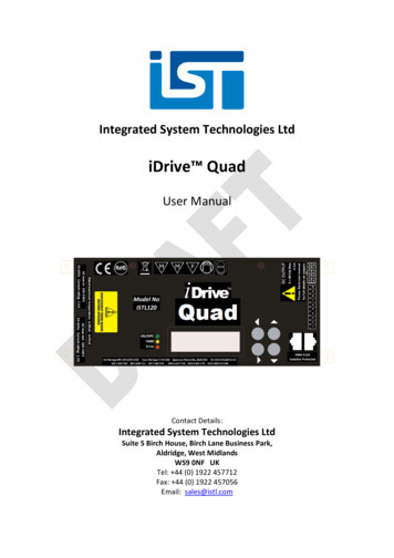
Integrated System Technologies LtdiDrive QuadUser ManualContact Details:Integrated System Technologies LtdSuite 5 Birch House, Birch Lane Business Park,Aldridge, West MidlandsWS9 0NF UKTel: 44 (0) 1922 457712Fax: 44 (0) 1922 457056Email: sales@istl.com
2010, Integrated System Technologies LtdiDrive Quad User ManualIntegrated System Technologies Limited Patent PortfolioIntegrated System Technologies Limited strongly respect innovation and know-how and theorganisation continues to invest significantly in developing an intellectual property portfoliocovering Lighting, LED fixtures, power supplies and LED drivers in order to protect its innovation.Related PatentsThe following patents and patent applications may apply:United Kingdom Patent No(s): 2,340,215; 2,369,730; 2,408,315; 1,433,363; 0720488.6; 0814255.6Japan Patent No: 4445082United States Patent No(s): 6,422,718; 6,963,175; 11/912 098; 12/738 750; US-2010-0264832-A1Australia Patent No(s): 2002321596;Czech Republic Patent No: 1,433,363Denmark Patent No: 1,433,363France Patent No: 1,433,363Germany Patent No: 602 31 418.6Ireland Patent No: 1,433,363Italy Patent No: 1,433,363Luxembourg Patent No: 1,433,363Monaco Patent No: 1,433,363Switzerland Patent No: 1,433,363The Netherlands Patent No: 1,433,363Sweden Patent No: 1,433,363European Patent Application No(s): 05735894.7; 08750475.9;PCT Patent Application No: PCT/GB2009/001923Information furnished by Integrated System Technologies is believed to be accurate and reliable.However, no responsibility is assumed by Integrated System Technologies for its use, nor for anyinfringements of patents or other rights of third parties that may result from its use. Specificationssubject to change without notice. No license is granted by implication or otherwise under anypatent or patent rights of Integrated System Technologies. Trademarks and registered trademarksare the property of their respective owners.User Manual Quad v1-5 24-02-11Page2 of 23
2010, Integrated System Technologies LtdiDrive Quad User ManualCONTENTSChapter 1: Introduction. 41.11.21.3Features .4Applications .4Safety Warnings.4Chapter 2: Mounting and Installation . 52.12.22.32.42.2Installation considerations .5QUAD DOs and DON’Ts.6Guidelines for Optimum EMC Performance .7Unit Connection .8Cable type / length limitations for different LED loads .10Chapter 3: Unit Setup and Operation . 113.13.23.33.43.53.63.73.83.9Unit Power-Up Sequence .11Quad LCD Control Panel.12Menu Map .13Menu Options and Descriptions .14DMX SETUP.14EFFECT SETUP .14FIXTURE SETUP .15OBSERVE .15LCD CONTRAST .15Example scenarios for Current setup .16RDM Functionality (From software version 1.28 onwards) .17LED Driver Thermal Protection .19Motherboard Thermistor .19Output Stage Digital Temperature Sensors .19LED Fixture Thermal Protection .20Setting LED Fixture Thermal Protection .21LED Driver Standby Mode (Energy Efficiency Mode) .22DMX Receiver Mode - Standby .22Stand-Alone Mode or DMX Master Mode- Standby .22Chapter 4: Technical Data . 23User Manual Quad v1-5 24-02-11Page3 of 23
2010, Integrated System Technologies LtdiDrive Quad User ManualChapter 1: IntroductionThe iDrive Quad is a multiple current source solution, which caters for applications for up to120W (at 25oC). The 4 channel DMX-512 controllable independent current sources, allow all theflexibility you need in driving your high brightness LEDs.1.1 Features DMX512-A compliant with auto-addressing functionality RDM – Remote Device Management Setup via front panel LCD interface Smooth LED light dimming Continuous current output eliminates flickering Very high efficiency (up to 95%) Auto Load Detection – Allowing connection of multiple LEDs per channel Self diagnostics prevent damage to the unit and to the LEDs Wrong wiring, open/short protection for each output with indication on LCD TP – Thermal protection of LEDs on each output (on supported LED luminaires) DRTP – Thermal Protection algorithm prevents driver from overheating1.2 Applications Architectural illuminations LED Lighting effects Theatrical LED lighting Commercial Lighting Home Lighting1.3 Safety Warnings1. The unit is intended for maximum operating ambient temperature 35oC.2. 10A shall be provided in building installation for connection to the mains supply.User Manual Quad v1-5 24-02-11Page4 of 23
2010, Integrated System Technologies LtdiDrive Quad User ManualChapter 2: Mounting and InstallationThe iDrive Quad is a stand-alone or wall mountable solution (fixings not included).For proper installation and subsequent operation of each unit, pay special attention to thefollowing recommendations: Upon unpacking the product, inspect the contents of the carton for shipping damages. Donot install damaged units. Ensure proper ventilation of each unit and avoid areas where corroding, deteriorating orexplosive vapours, fumes or gases may be present. Allow for proper clearance of unit enclosure and wiring terminals for easy access, hardwareconfiguration and maintenance. Ensure the unit is securely attached, properly mounted if positioned in a rack enclosure,and free of excessive vibration. Avoid touching the chassis surface during the operation, power down the unit and allow itto cool down before touching the chassis. The chassis can get hot during a continuous operation with a connected load Ensure that the power is disconnected before installing, wiring, or servicing the unit. Do not attempt to install or use the unit until you read and understand the installationinstructions and safety labels. Do not use the product if power cables are damagedThe instructions and precautions set forth in this user manual are not necessarily all-inclusive orrelevant to all applications as IST cannot anticipate all conceivable or unique situations.2.1Installation considerationsThe iDrive Quad model may be mounted on any of two surfaces using standard M4 screws. Thedriver chassis comes with four mounting points on the base as shown in figure 2.1a with maximumallowable torque of 2Nm. Ideally, the driver should be firmly secured to a permanent wall orceiling and is suitable for indoor purposes only but if there are aspects of the installationenvironment that may cause concern please contact IST on support@istl.com for furtherinstallation support.When selecting a mounting location and orientation, the unit should be positioned so air flow isnot restricted. Maintain a 50mm minimum clearance around all sides of the driver and route allcables so airflow is not obstructed. If the unit is mounted in a horizontal position with the LCDscreen facing upwards, this could cause permanent heat damage to the LCD display and the driverSHOULD be mounted or freestanding vertically so the LCD is on the side of the driver. (see fig 2.1a)If a large number of units are installed in a very small area it is essential that there is adequateventilation and airflow to ensure that any excess heat generated from the PSU units should beremoved from the area otherwise the drivers may not operate as intended.Avoid excessive bending of input or output power cables after they are connected to the iDrive Quad drivers.User Manual Quad v1-5 24-02-11Page5 of 23
2010, Integrated System Technologies LtdiDrive Quad User ManualFor high-current outputs, use cable-ties to support heavy cables and minimize mechanical stresson output connectors. Be careful not to short-out to neighbouring output connectors.Avoid applications in which the unit is exposed to water or high humidity levels that exceed thespecified levels. In such applications, an IP enclosure mounting design is required taking intoaccount the thermal considerations of the driver. The iDrive Quad has been designed for indooruse only.Avoid applications in which the unit is exposed to excessive shock or vibration levels that exceedthe specified levels. In such applications, a shock absorption mounting design is required.INSTALLTION MOUNTING GUIDEMounting PointsMin 50mmclearanceAirflowMin 50mmclearanceMin 50mmclearanceMin 50mmclearanceFigure 2.1aMountingSurface2.2QUAD DOs and DON’Ts Do not unplug the LED driver while input power is applied to the iDrive Quad as transientspikes to the driver may cause damage. Do not restrict airflow to the unit as high power, high efficiency LED drivers still require heat tobe dissipated from the unit in order to meet expected operation. Keeping LED drivers well belowmaximum operating temperature will improve the lifetime characteristics. If large numbers of LEDdriver units are placed in a small area such as a maintenance area then ensure there is adequateventilation and airflow in order to dissipate any excess heat. Always ensure that output connector to the LED fixture are properly wired and connected to theunit before applying power. Some types of LED emitters can fail if plugged directly into a PSU thatis already switched on.User Manual Quad v1-5 24-02-11Page6 of 23
2010, Integrated System Technologies LtdiDrive Quad User Manual Positive and Negative power cables should be run next to each other to minimize inductance. Always wait until the LEDs within an LED fixture have gone off after shutting off power to theLED driver. The LED driver assemblies do not have user serviceable components. They must be returned tothe factory for repairs. Contact Customer Service for a RMA number before returning the unit. Donot attempt to repair or modify the power supply in any manner as this will void any warranty. Use proper size wires to avoid overheating and excessive voltage drop. Do not spill or expose the iDrive Quad LED driver to water or high levels of humidity. Do not power the iDrive Quad unit from a mains dimmer switch as the unit is not designed forsuch devices. Only use the iDrive Quad units on the appropriate input voltage supplies. Please check the ACvoltage range is compatible with the specifications outlined for the driver.2.3Guidelines for Optimum EMC PerformanceThe iDrive Quad LED Driver series is designed to comply with European Normative limits (EN) forconducted and radiated when correctly installed in a system. However, power supply compliancewith these limits is not a guarantee of system compliance and it is recommended that the fullsystem is designed to meet the relevant EMC EN standards. System EMC performance can beimpacted by a number and combination of items. Design consideration such as PCB layout andtracking, cabling arrangements and orientation of the power supply amongst others all directlycontribute to the EMC performance of a system.Cabling arrangements and PCB tracking layouts are the greatest contributing factor to system EMCperformance. It is important that PCB tracks and power cables are arranged to minimise currentcarrying loops that can radiate, and to minimise loops that could have noise currents induced intothem.All cables and PCB tracks should be treated as radiation sources and antennae and every effortshould be made to minimise their interactiona. Keep all cable lengths as short as possible.b. Minimise the area of power carrying loops to minimise radiation, by using twisted pairs ofpower cables with the maximum twist possible.c. Run PCB power tracks back to back.d. Minimise noise current induced in signal carrying lines, by twisted pairs for sense cables withthe maximum twist possible.e. Do not combine power and sense cables in the same harnessf. Ensure good system grounding. System Earth should be a “starpoint” and all other earths shouldgo to the ‘starpoint”The Quad LED driver has been tested and approved to relevant EN standards.User Manual Quad v1-5 24-02-11Page7 of 23
2010, Integrated System Technologies LtdiDrive Quad User Manual2.4Unit ConnectionThe iDrive Quad has an AC mains IEC input and also a mains IEC output to link the AC supply toadditional units. It also has 2 x RJ45 connectors for the DMX-512A. The lighting fixture can beconnected to the DC output via a 10 pin terminal connector or a 10 pin molex connector.Please ensure that all cables are wired correctly and the cables are supported if they are long or heavilybent in order to reduce stresses on the driver PCB board.MAINS INPUTThe product can be connected to 100V 240V mains supplies with an AC mains outlet forconnection to additional units.Make sure the number of units connected in series from a single loop-in loop-out power cable does notexceed the current rating of the power cable or the circuit breaker specifications, otherwise normaloperation may be affected.DMX-512AThe DMX-512A is connected via RJ45 connectors, configuration as below:FunctionGroundGroundData Data Aux Data Aux Data RJ45 reenWhite/GreenXLR Pin112345ColourBlackBlackBlueRed-PLEASE NOTE: Before connecting any DMX controller, refer to the installation guide of the DMX controllermanufacturer.OUTPUTSThe fixtures are connected using 10 pin terminal connectors or 10 pin molex connectors.10 Pin Terminal10 Pin MolexPin 1Pin 10User Manual Quad v1-5 24-02-11Page8 of 23
2010, Integrated System Technologies LtdiDrive Quad User ManualThe quad is capable of controlling fixtures using common anode cabling. Pin details for standardcabling and common anode cabling as follows:Pin Details for standard wiringPin 1Channel 1 Pin 2Channel 1 Pin 3Channel 2 Pin 4Channel 2 Pin 5Channel 3 Pin 6Channel 3 Pin 7Channel 4 Pin 8Channel 4 Pin 9ThermistorPin 10ThermistorPin details for Common AnodePin 1Common AnodePin 2Channel 1 Pin 3Not connectedPin 4Channel 2 Pin 5Not connectedPin 6Channel 3 Pin 7Not connectedPin 8Channel 4 Pin 9ThermistorPin 10ThermistorThe Quad driver features the TP – Fixed Thermal Protection which protects the LED fixture fromoverheating while maintaining light output. For more information about thermal protection,please see the TP – Fixture Thermal Protection section.PLEASE NOTE: If the NTC sensor is not connected, TP protection will be disables for that output.User Manual Quad v1-5 24-02-11Page9 of 23
2010, Integrated System Technologies LtdiDrive Quad User Manual2.5Cable type / length limitations for different LED loadsLED wiring should use AWG18 cable. Please refer to cable type / length limitations tables belowfor selecting the correct cable type.At driving current 2.300.920.580.36VoltageDrop@ MAX xLEDs1Km971XXXAt driving current .300.920.580.36VoltageDrop@ MAX xLEDs150m1313121085At driving current 2.0531.451.0240.6440.5110.405 MaxCurrent(A)9.304.702.300.920.580.36VoltageDrop@ MAX axLEDs150m121111851All max. LEDs’ values are per channelLED figures are based upon 2 x voltage drop to cover the voltage drop to and from the fixtureUser Manual Quad v1-5 24-02-11Page10 of 23
2010, Integrated System Technologies LtdiDrive Quad User ManualChapter 3: Unit Setup and Operation3.1Unit Power-Up SequenceAfter applying power to the unit, it will perform a quick self test for correct output LED wiring anda proper voltage from the DC power supply. Each of these tests is followed by correspondingmessages on the LCD screen.LED Wirings TestThe product has a unique, algorithm for detecting load type and wrong LED connections. It candetect if the LED’s ( ) and (-) lines are having a short circuit between them or mixed connectionwith a neighbour channel inside the plug terminal. If the unit detects an incorrect wiring on one ofthe outputs, that group of channels will not be operational until the problem is fixed.If during normal operation some of the LEDs are reconnected, the LED wiring test will be initiatedon the group which the disconnected channel belonged to. That way LEDs can be hot-plugged intosystem, however connecting/disconnecting LED while powered on is not recommended. It isalways better to make all of the connections first and then turn the power on.Auto Load DetectionEach channel of the Quad is capable of auto-detecting the LED load type connected to it andselecting the appropriate operating mode to control that load.Driver Thermal ProtectionThe Quad has internal temperature sensor which allows it to monitor the temperature of theinternal power circuitry. If by any reason external ambient temperature rises above the permittedlimit, the unit will not allow
iDrive Quad User Manual Page User Manual Quad v1-5 24-02-11 4 of 23 Chapter 1: Introduction The iDrive Quad is a multiple current source solution, which caters for applications for up to 120W (at 25 oC). The 4 channel DMX-512 controllable independent current sources, allow all the f
