Transcription
Instruction ManualGeneral application InverterIMO iDrive 2 XKLThank you for purchasing our iDrive XKL series of inverters. This product is designed to drive a three-phase induction motor. Read through this instruction manual and be familiar withthe handling procedure for correct use. Improper handling might result in incorrect operation, a short life, or even a failure of this product as well as the motor. Deliver this manual to the end user of this product. Keep this manual in a safe place until this product is discarded. For how to use an optional device, refer to the instruction and installation manuals for that optional device.IMO Precision Controls Ltd.XKL-MANUAL1
Copyright 2014 IMO Precision Controls LtdAll rights reserved.No part of this publication may be reproduced or copied without prior written permission from IMO Precision Controls Ltd.All products and company names mentioned in this manual are trademarks or registered trademarks of their respective holders.The information contained herein is subject to change without prior notice for improvement.2
Content .Error! Bookmark not defined.1 Safety Precautions . 41.1 Safety definition . 41.2 Warning symbols . 41.3 Safety guidelines . 42 Product overview . 72.1 Quick start-up . 72.2 Product specification . 82.3 Name plate . 92.4 Type designation key . 102.5 Rated specifications . 102.6 Structure diagram . 103 Installation Guidelines . 123.1 Mechanical installation . 123.2 Standard wiring . 143.3 Layout protection . 164 Keypad Operation Procedure . 184.1 Keypad displaying . 194.2 Keypad operation . 205 Function Parameters . 226 Fault tracking . 636.1 Maintenance intervals . 636.2 Fault solution . 677 Communication protocol . 697.1 Brief instruction to Modbus protocol . 697.2 Application of the inverter. 697.3 RTU command code and communication data illustration . 73Appendix A Technical data . 82A.1 Ratings . 82A.2 CE . 82A.3 EMC regulations . 83Appendix B Dimension drawings . 84B.1 Keypad structure . 84B.2 Inverter chart . 84Appendix C Peripherial options and parts . 85C.1 Peripherial wiring . 85C.2 Power supply. 86C.3 Cables . 86C.4 Breaker and electromagnetic contactor . 86C.5 Reactors . 87C.6 Filter . 88C.7 Braking system . 88Appendix D Further information . 903
iDrive 2 invertersSafety Precautions1 Safety PrecautionsPlease read this manual carefully and follow all safety precautions before moving, installing, operating andservicing the inverter. If ignored, physical injury or death may occur, or damage may occur to the devices.IMO are not responsible for any physical injury or death to persons or damage to the devices if the safetyprecautions in the manual are not complied with.1.1 Safety definitionDanger:Serious physical injury or even death may occur if Danger safetyWarning:Physical injury or damage to the devices may occur if Warning safetyrequirements are not followed.requirements are not followed.Note:Physical injury may occur if above instructions are ignored.QualifiedOnly qualified Engineers with extensive knowledge and experience ofelectricians:commissioning and installation should attempt to install these devices. Allsafety precautions must be taken when installing.1.2 Warning symbolsWarnings caution you about conditions which can result in serious injury or death and/or damage to the equipment,and advice on how to avoid the danger. The following warning symbols are used in this ostaticDo notdischargeHot sidesHot sidesNoteNoteInstructionAbbreviationSerious physical injury or even death mayoccur if requirements are not followed.Physical injury or damage to the devicesmay occur if requirements are not followed.Damage to the PCBA board may occur ifrequirements are not followed.Sides of the device may become hot. Donot touch.Physical injury may occur if requirementsare not followed.Note1.3 Safety guidelines Only qualified electricians are allowed to operate on the inverter. Do not perform any wiring and inspection or changing components when the powersupply is applied. Ensure all input power supply is disconnected before wiring andchecking and always wait for at least the time designated on the inverter or until the DCbus voltage is less than 36V. Below is the table of the waiting time:Inverter moduleSingle-phase0.4kW-2.2kW230VThree-phase 400V0.75kW-2.2kWMinimum waiting time5 minutes5 minutes Install the inverter according to manual; otherwise fire, electric shock or other injury mayoccur.4
iDrive 2 invertersSafety Precautions The base of the heatsink may become hot during running. Do not touch to avoid injury. The electrical parts and components inside the inverter are electrostatic. Takeprecautions to avoid electrostatic discharge during relevant operation.1.3.1 Delivery and installation Please install the inverter on fire-retardant material and keep the inverter away fromcombustible materials. Connect the optionl braking components (braking resistors) according to the wiringdiagram. Do not operate on the inverter if there is any damage or components loss to theinverter. Do not touch the inverter with wet items or body, risk of electric shock.Note: Select appropriate moving and installing tools to ensure a safe and normal running of the inverter and avoidphysical injury or death. For physical safety, the installer should take some mechanical protectivemeasurements, such as wearing exposure shoes and working uniforms. Protect against physical damage or vibration during delivery and installation. Do not carry the inverter by its cover. Install away from children and other public places. The inverter cannot meet the requirements of low voltage protection in IEC61800-5-1 if the sea level ofinstallation site is above 2000m. The Earth leakage current of the inverter may be above 3.5mA during operation. Ground with propertechniques and ensure the grounding resistor is less than 10Ω. The conductivity of PE grounding conductoris the same as that of the phase conductor (with the same cross sectional area). R, S and T are the input terminals of the power supply, while U, V and W are the motor terminals. Pleaseconnect the input power cables and motor cables correctly; otherwise the damage to the inverter may occur.1.3.2 Commissioning and running Disconnect all power supplies applied to the inverter before the terminal wiring andwait for at least the designated time after disconnecting the power supply. High voltage is present inside the inverter during running. Do not carry out anyoperation except for the keypad setting. The inverter may auto start when P01.21 1. Do not get close to the inverter andmotor. The inverter cannot be used as “Emergency-stop device”. The inverter cannot be used to brake the motor suddenly. A mechanical brakingdevice should be used.Note: Do not switch on/off the input power supply of the inverter frequently. For inverters that have been stored for a long time, check and fix the capacitance and try to run it againbefore utilization (see Maintenance and Hardware Fault Diagnosis). Replace top cover before running, otherwise electric shock may occur.5
iDrive 2 invertersSafety Precautions1.3.3 Maintenance and replacement of components Only qualified electricians should perform the maintenance, inspection, andcomponents replacement of the inverter. Disconnect all power supplies to the inverter before the terminal wiring. Wait for atleast the time designated on the inverter after disconnection. Take measures to avoid screws, cables and other conductive matters to falling intothe inverter during maintenance and component replacement.Note: Ensure screws are tightened to the correct torque. Keep the inverter, parts and components away from combustible materials during maintenance andcomponent replacement. Do not perform any isolation and pressure test on the inverter and do not perform a megger test on theinverter.1.3.4 What to do after scrapping The inverter contains hazardous materiels. Dispose of according to WEEEregulations.6
iDrive 2 invertersProduct overview2 Product overview2.1 Quick start-up2.1.1 Unpacking inspectionCheck as followings after receiving products:1. Check that there is no physical or water damage to the package. Contact supplier immediately ifreceived damaged.2. Check the information on the type designation label on the outside of the package to verify that thedrive is of the correct type. If not, contact supplier immediately.3. Check that there are no signs of water in the package and no signs of damage or breach to theinverter. Contact supplier immediately if any damage.4. Check the information on the type designation label on the outside of the package to verify that thename plate is of the correct type. If not, contact supplier immediately.5. Check to ensure the accessories (including user’s manual and control keypad) inside the device iscomplete. If not, contact supplier immediately.2.1.2 Application confirmationCheck the machine before beginning to use the inverter:1. Check the load type to verify that there is no overload of the inverter during work and check thedrive is the correct power rating.2. Check that the actual current of the motor is equal to or less than the rated current of the inverter.3. Check that the control accuracy of the load is the same of the inverter.4. Check that the incoming supply voltage is correspondent to the rated voltage of the inverter.2.1.3 EnvironmentCheck as followings before the actual installation and usage:1. Check that the ambient temperature of the inverter is below 40 . If exceeds, derate 3% for everyadditional 1 . Additionally, the inverter can not be used if the ambient temperature is above 50 .Note: for the cabinet inverter, the ambient temperature means the air temperature inside the cabinet.2. Check that the ambient temperature of the inverter in actual usage is above -10 . If not, addheating facilities.Note: for the cabinet inverter, the ambient temperature means the air temperature inside the cabinet.3. Check that the altitude of the actual usage site is below 1000m. If exceeds, derate1% for everyadditional 100m.4. Check that the humidity of the actual usage site is below 90% and condensation is not allowed. Ifnot, add additional ant-condensation heaters.5. Check that the actual usage site is away from direct sunlight and foreign objects can not enter theinverter. If not, add additional protective measures.6. Check that there is no conductive dust or flammable gas in the vicinity of the drive. If not, addadditional protection to inverters.2.1.4 Installation confirmationCheck as followings after the installation:1. Check that the load range of the input and output cables meet the need of actual load.7
iDrive 2 invertersProduct overview2. Check that the accessories of the inverter are correctly and properly installed. The installationcables should meet the needs of every component (including reactors, input filters, output reactors,output filters, DC reactors and braking resistors).3. Check that the inverter is installed on non-flammable materials and the calorific accessories(reactors and brake resistors) are away from flammable materials.4. Check that all control cables and power cables are run separately and the routed to comply withEMC requirements.5. Check that all grounding systems are properly grounded according to the requirements of theinverter.6. Check that the free space during installation is sufficient according to the instructions in user’smanual.7. Check that the installation conforms to the instructions in user’s manual. The drive must beinstalled in an upright position.8. Check that the external connection terminals are tightly fastened and the torque is appropriate.9. Check that there are no screws, cables and other conductive items left in the inverter.2.1.5 Basic commissioningComplete the basic commissioning as follows before actual operation:1. Autotune. If possible, de-coupled from the motor load to start dynamic autotune. Or if not, staticautotune is available.2. Adjust the ACC/DEC time according to the actual running of the load.3. Commission the device via jogging and check that the rotation direction is as required. If not,change the rotation direction by changing the wiring of motor.4. Set all control parameters to suit application.2.2 Product specificationFunctionInput voltage (V)Power inputInput current (A)Input frequency (Hz)Power outputThree-phase 380(-15%) 440( 10%)Refer to table 2.550Hz or 60HzAllowed range: 47 63Hz the input voltage (errorOutput current (A)Refer to table 2.5Output power (kW)Refer to table 2.5Control modeMaximum outputcontrolSingle-phase 220(-15%) 240( 10%)Output voltage (V)Output frequency d ratio 5%)50Hz/60Hz, fluctuation: 5%V/F400Hz1:100150% of rated current: 1 minuteOverload capability180% of rated current: 10 seconds200% of rated current: 1 secondRunningKey functionsStop mode and anti-overtemperature of the bus8
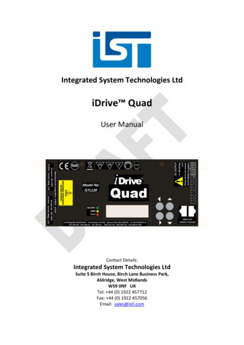
iDrive 2 invertersProduct surement accuracyTerminal switch inputresolutionTerminal analog inputresolutionOvertemperature point 3 2ms 20mVAnalog input1 input 0 10V/0 20mAAnalog output1 input 0 10V/0 20mADigital input5 common input1 Y output (commonly used with digital output) and 1Digital outputprogrammable relay outputCommunication485 communicationDigital setting, analog setting, multi-step speedsetting, PID setting, MODBUS communication settingFrequency settingand so onSwitch between different settingsAutomatic voltageKeeps output voltage stable when the grid voltageadjustmentchangesFault protectionMore than 10 fault protectionsMountable methodWall mountableTemperature of therunning environment-10 50 , derate above 40 Single/three-phase 230V 0.2-0.75kW natural coolingOthersCoolingSingle/three-phase 230V 1.5-2.2kW, three-phase380V 0.75-2.2kWBraking unitEmbeddedDC reactorNot optionalBraking resistorOptional and externalOptional EMC filtersC2 or C3 filter options2.3 Name plateFig 2-1 Name plate9
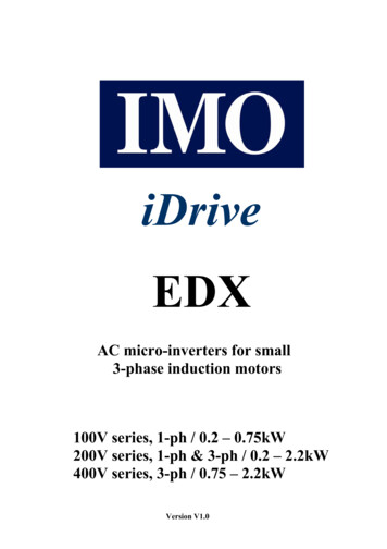
iDrive 2 invertersProduct overview2.4 Type designation keyThe type designation contains information on the inverter. The user can find the type designation on the typedesignation label attached to the inverter or the simple name plate.XKL – 220 – 2 1①②③④Fig 2-2 Product typeField identificationSignDetailed description of the signDetailed contentAbbreviation①Product abbreviationSeries XKLRated power②Power range220 2.2kWVoltage③Supply voltagePhase④Input Phase4: 380(-15%) 440( 10%)2: 220(-15%) 240( 10%)1 1Ph
Instruction Manual General application Inverter IMO iDrive 2 XKL Thank you for purchasing our iDrive XKL series of inverters. This product is designed to drive a three-phase induction motor. Read through this instruction manual and