Transcription
iDriveEDXAC micro-inverters for small3-phase induction motors100V series, 1-ph / 0.2 – 0.75kW200V series, 1-ph & 3-ph / 0.2 – 2.2kW400V series, 3-ph / 0.75 – 2.2kWVersion V1.0
Quick Start GuideQuick Start GuideThis guide is to assist in installing and running the inverter to verify that the drive and motorare working properly. Starting, stopping and speed control will be from the keypad. If yourapplication requires external control or special system programming, consult the iDrive EDXinstruction manual supplied with your inverter.Step 1 - Before starting the inverterPlease refer to chapter one (Preface) and chapter two (Safety Precautions) of the iDrive EDXinstruction manual. Verify drive is installed in accordance with the procedures as described inchapter three (Environment and installation). If something is suspected of being abnormal, donot start the drive until qualified personnel have corrected the situation. (Failure to do socould result in death or serious injury.)x Check inverter and motor nameplates to determine that they have the same power andvoltage ratings. Ensure that full load motor current does not exceed that of the inverter.x With power OFF, remove the terminal covers to expose the motor and power terminals.a. Verify that AC power is wired to L1(L), L2, and L3(N) .b. Verify that motor leads are connected to T1, T2, and T3 .c. If a brake module is necessary, please connect terminal voltage of the braking unit to Pand N of the inverter. Never connect a resistor directly to terminals P and tep 2 - Apply power to the driveApply AC power to the drive and observe the keypad display. The 7-segment LED displayshould show power voltage for 3 5 seconds and then show Frequency Command, factory setat 5.00. (Frequency Command shown on 7-segment display should be flashing.)i
Step 3 - Check low speed motor rotation without load.z Press RUN key. 7-segment display will indicates 00.0 to 05.0. This number is thefrequency output value. The display will now become solid (not blinking) because theinverter output is on.z Check the operating direction of the motor.IF the direction of the motor is incorrect:Press STOP key, turn off the AC power supply. When the power indicator LED is off,change over motor connections T1 and T2.Apply the power again, then check the motor direction.z Press STOP key.Step 4 - Check full speed at 50Hz / 60Hzz Change the frequency with ¿,À keys, press DATA/ENT after setting frequency.z Set frequency to 50Hz / 60Hz according to the above.z Press RUN key; check that the motor accelerates smoothly to full speed.z Press STOP key; check that the motor decelerates smoothly to zero speed.Step 5 - Other settingsFor other functions, please refer to iDrive EDX user manual.Upper frequency limit . P. 4-9Lower frequency limit .P. 4-9Acceleration time P. 4-10Deceleration time P. 4-10Control mode (Vector, V/F) P. 4-10Motor rated current P. 4-13ii
iDrive EDX user manualContentsQuick Start Guide . iChapter 0 Preface . 0-10.1 Preface . 0-10.2 Product inspection . 0-1Chapter 1 Safety precautions 1-11.1 Operation precautions . 1-11.1.1 Before power up . 1-11.1.2 During power up . 1-21.1.3 Before operation . 1-21.1.4 Leakage current! . 1-21.1.5 During operation 1-31.1.6 Operating environment .1-3Chapter 2 Part number description . .2-1Chapter 3 Environment description and installation . 3-13.1 Environment . 3-13.2 Environment precautions . 3-63.3 Electrical Installation . 3-73.3.1 Notice for wiring . 3-73.3.2 MC, MCCB, Fuse and cable specifications . 3-93.3.3 Ancillary power equipment – supply side 3-103.3.4 EMC: Good wiring practice – motor side . 3-113.4 Specification . 3-133.4.1 Product individual specification. . 3-133.4.2 General specifications 3-143.5 Connection diagram . 3-163.6 Description of inverter terminals . . . . 3-173.7 iDrive Dimensions . . . 3-203.8 Multi-iDrive installation with regenerative loads . . 3-23iii
Chapter 4 Programming instructions & Parameter list . .4-14.1 Keypad description 4-14.1.1 Keypad display and operation instruction . 4-14.1.2 Keypad navigation 4-14.2 Parameter function list . 4-34.3 Parameter function description . 4-9Chapter 5 Trouble shooting and maintenance 5.1 Fault indication and remedy .5.1.1 Fault/Error display and Diagnostics 5.1.2 Set up & Interface Errors . .5.1.3 Keypad operation error descriptions 5.2 General functional troubleshooting . .5.3 iDrive Troubleshooting flowcharts . 5.4 Routine and periodic checks . .5.5 Maintenance and inspection .Chapter 6 Options . .6.15-15-15-15-45-55-65-75-135-146-1Option cards . . 6-16.1.1 RS-485 option card . 6-16.1.2 RS-232 option card . 6-26.1.3 Program copy option card . 6-36.1.4 Remote keypad . 6-46.1.5 2 IN/OUT Card 6-5Appendix 1 iDrive EDX inverter parameter setting list Appendix 1iv
Chapter 0 PrefaceChapter 0 Preface0.1 PrefaceTo extend the performance of the product and ensure your safety, read this manual thoroughly beforeusing the inverter. Should there be any problem in using the product that can not be solved with theinformation provided in the manual, contact your nearest IMO distributor or the company from whoyou purchased the inverter from.PrecautionsThe inverter is an electrical / electronic product. For your safety, there are symbols such as “Danger”and “Caution” in this manual to remind you to pay attention to safety instructions on carrying,installing, operating, and checking the inverter. Be sure to follow the instructions carefully for safety.DangerIndicates a potential hazard that may cause death or serious personalinjury if misusedCautionIndicates that the inverter or a mechanical system might be damaged ifmisused Dangerz Do not touch any circuit boards or internal parts until the charge indicator is extinguishedafter turning the power off.z Do not connect any wires when the inverter is powered. Do not check parts and signals oncircuit boards when the inverter is in operation.z Do not disassemble the inverter and modify internal wires, circuits and parts.z Connect the ground terminal of the inverter correctly. Always follow local / nationalregulations. Cautionz Do not perform a high voltage insulation test on parts inside the inverter. High voltages caneasily destroy the inverter’s semiconductor components.z Do not connect T1 (U), T2 (V), and T3 (W) terminals of the inverter to AC power source.z CMOS ICs on the inverter’s main board are sensitive to static electricity.Do not touch the main p c board even when power is off, or damage may occur.0.2 Product InspectioniDrive EDX inverters have all passed a full function test before delivery. Please check thefollowing when you receive and unpack the inverter:The model and capacity of the inverter is the same as those specified on your order.z z Is there any damage caused by transportation? If so, do not apply power.Contact IMO distributor or sales representative if any of the above are found to be incorrect.0-1
Chapter 1 Safety PrecautionsChapter 1 Safety Precautionsʳ ˁ Operation Precautionsʳ ˁ ˁ Before Power UpʳCautionThe line voltage applied must comply with the inverter’s specified input voltage.ʳʳDangerMake sure the main circuit connections are correct. L1(L), L2, and L3(N) are power-inputterminals and must not be confused with T1, T2 and T3. Otherwise, the inverter might bedamaged.ʳʳʳCautionz To avoid the front cover from disengaging, do not pull the cover when carrying the inverter forwhich the heat sink should be held. Avoid dropping the inverter as damage could occur.z To avoid fire, do not install the inverter on a flammable surface. Always install on metalsurface if possible.z If several inverters are placed in the same control panel, add extra heat dissipators to keep thetemperature below 50oC to avoid overheating or fire.z When removing or installing the remote keypad, turn the power off first, and operate thekeypad following the instruction diagrams to avoid error or no display caused by poorcontact.WarningThis product complies with IEC 61800-3, with built-in filter for Unrestricted Distributionand when using an external filter for Restricted Distribution. Conformance should be testedbefore use in some environments.ʳ1-1
Chapter 1 Safety Precautions1.1.2 During Power upDangerzThe inverter still has control power if the time of power loss is very short. When thepower is re-supplied, the inverter operation is controlled by F41.zThe inverter operation is controlled by F04 and C09 and the status of (FWD/REV RUNswitch) when power is re-applied. (and F39 /F40) Power loss ride through / Auto resetafter fault.1. When F04 000, the inverter will not auto restart when power is re-applied.2. When F04 001 and operation switches (FWD/REV RUN) are OFF, the inverter willnot auto restart when power is re-applied.3. When F04 001 and operation switch ON and C09 000, the inverter will auto restartwhen power is re-applied. Please turn OFF the run (start) switch to avoid damage tomachine and injury to operator before the power is re-applied.zWhen C09 000 (direct start on power up), please refer to the description of C09 to verifythe safety of operator and machine.1.1.3 Before operationCautionMake sure the model and capacity are the same as those set by F00.ʳʳ1.1.4 Earth / ground leakage currentWarningWarning ! iDrive EDX series built-in filter type can give leakage current 3.5mA.ALWAYS ENSURE INVERTER IS CORRECTLY EARTHED / GROUNDED.Operation with ungrounded supplies:DO NOT use iDrive EDX inverters on ungrounded (floating) power supplies.Operating iDrive EDX with Residual Current Device (RCD):1.Inverter leakage current may cause nuisance trip when RCD setting is 100mA2. Only one inverter should be supplied from each RCD.1-2
Chapter 1 Safety Precautions1.1.5 During operationDangerDo not connect or disconnect the motor while inverter is operating the motor otherwise the inverterand/or the disconnecting device may be damaged by the high level of switch-off current.ʳʳʳʳDangerz To avoid electric shock, do not remove the front cover when power is on.After a power-loss trip (under-volt) trip occurs, the motor will restart automatically when power isrestored if auto-restart function is set. In this case, care must be taken while working with the machine.z Note: External Emergency stop must open and un-latch the power supply to the inverter withoutany chance of re-closing until required. Do not rely upon software control for Emergency stop.ʳʳCautionz Do not touch heat-generating components such as heat sink and brake resistor.z The inverter can operate the motor from low speeds to very high speeds.Verify the allowable speed ranges of the motor and the load before operation.z Note the settings related to the braking unit.z Do not check signals on circuit PCB while the inverter is running.ʳʳCautionAllow a minimum of 5 minutes after power down before attempting to disassemble orchecking the components within the drive.ʳʳ1.1.6 Operating environmentCautionWhen the inverter top dust cover has been removed it can be used in a non-condensingatmosphere in temperature range from –10oC to 50 oC and relative humidity of 95%, butthe environment should be free from corrosive gasses, condensation and metallic dust.ʳ1-3
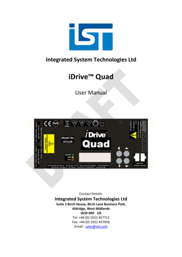
Chapter 2 Model descriptionChapter 2 Part numbering descriptioniDrive product rating label (example)Do not inspect components unless the lamp is offSee manual for correct installation and operation! CAUTIONModel: EDX-040-21-EINPUT: AC 1 phase 50 / 60HzOUTPUT:AC 3 phases 0 – 200HzMotor Rating: 0.5HP / 0.4KWVOLTAGE: 200 – 240V ( 10%, -15%)VOLTAGE:0 - VINIRMS : 5.4AIRMS : 3.1AIP20 / UL Open Type (rated -10 C to 50 C Ambient)IMO Precision Controls LtdWARNING: THIS PRODUCT MUST BE EARTHED!EDXSeries:-040Nominalmotor capacity:020:0.18kW / 0.25 HP040:0.37kW / 0.5 HP075:0.75kW / 1.0 HP150:1.5kW / 2.0 HP220:2.2kW / 3.0 HP-21Inputvoltage:Inputphases1:100V1:Single phase2:230V3:Three phase4:400V-E-EMC filter :EnclosureE: Integrated Filter N4S: IP65 waterand dust proofBlank: No FilterswitchN4:IP65 withoutwater and dustproof switchBlank: IP202-1
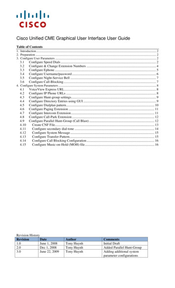
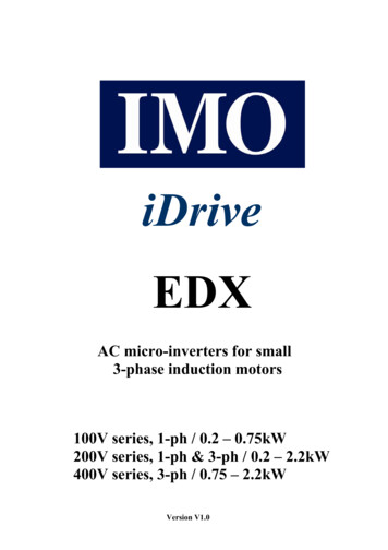
Chapter 3 Environment description and installationChapter 3 Environment description and installation3.1EnvironmentThe environment will directly effect the operation and the life of the inverter, so install theinverter in an environment that complies with the following conditions:z Ambient temperature: -10 50z Avoid exposure to rain or moisture.z Avoid direct sunlight.z Avoid smoke and salinity.z Avoid erosive liquid and gas.z Avoid dust and small metal pieces.z Keep away from radiative and flammablematerials.z Avoid electromagnetic interference (soldering machine, power machine).z Avoid vibration (punching machine). Add a vibration-proof pad if the situation can not beavoided.z If several inverters are placed in the same control panel, add extra heat dissipators to keepthe temperature below 50oC.iDriveAir exchanging faniDrive ́̆ ʳ̇ ʳ̃̂̊ ̅ʳ ̆̇̅ ̈̇̂̅(PE)iDriveAir exchanging fan ́̆ ʳ̇ ʳ̃̂̊ ̅ʳ ̆̇̅ ̈̇̂̅ ́̆ ʳ̇ ʳ̃̂̊ ̅ʳ ̆̇̅ ̈̇̂̅iDrive(Correct configuration)(Incorrect configuration)(Correct configuration)(Incorrect configuration)z Place the front side of the inverter onward and top upward to help heat dissipation.iDrive(A)Front view(B)Side view3-1
Chapter 3 Environment description and installationz The chassis of this model has DIN rail clip device to use when rail mounting.zThis model also can be installed side-by-side (when inside temperature below 50 ).IMOIMO3-2IMO
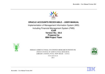
Chapter 3 Environment description and installationz iDrive EDX-###-##-N4X(IP65) type installation:(PE)NOTE :1. Power switch , REV-0-FWD switch and potentiometer are onlyfor EDX-######- N4S TYPE2. Power supply cable : 600V AC rated PVC3. Motor cable : 600V AC rated PVC / (screened or armoured)/PVC4. Maximum torque on terminal screws :(1). Power/motor cable (plug in) terminal : 5kg-cm(4.34 in-lb)(2). Remote control wire : 4kg-cm (3.47 in-lb)(3). Outer cover (M4) : 6kg-cm (5.20 in-lb)(PE)POWERSWITCHAC100 120or200 1FW(PE)(PE)RE24V10VPotentiometerVIN0V3-3NOTE:(1). Input power : single-phase (L1,L2, (PE))ensuring supply is 100 120 or 200 240 supplyaccording to model type.(2). Output / motor : three-phase (T1,T2,T3, (PE) ).Caution : Do not start or stop the motorby switching input powerΘFor EV-######-N4S type :Ensure that the REV-0-FWD switch is set at ‘0’position so that the iDrive has no run signalat power-on otherwise injury mayresult.
Chapter 3 Environment description and installationz EDX-###-##-N4S installation :TM2TM13-4
Chapter 3 Environment description and installationz EDX-###-##-N4 installation :TM2TM13-5
Chapter 3 Environment description and installation3.2 Environmental precautionsDo not use the inverter in an environment with the following conditions:Direct sunlightSaltFrame SizeCorrosive gas and liquidWind, rain, and waterdrops may get intoOilIron filings, dustExcessive vibrationExtreme low temperatureExcessive hightemperatureElectromagnetic waveand ultra high waveRadioactive materialsInflammable materials3-6
Chapter 3 Environment description and installation3.3 Electrical Installation3.3.1 Notice for wiringA. Screwdriver torque:Connect cables with a screwdriver or other suitable tools and follow the torque listed below.HorsepowerKW0.25/0.5/1 0.2/0.4/0.750.25/0.5/1 0.2/0.4/0.752/31.5/2.21/2/30.75/1.5/2.2Tightening torquePower sourceNominal torque for TM1 terminal0.74 / 1.00100-120V(lbs-ft / Nm)200-240V200-240V1.286 / 1.74(lbs-ft / Nm)380-480VB. Power cables:Power cables are wires connected to L1(L), L2, L3 (N), T1, T2, T3, P and N. Choose cable inaccordance with the following criteria:(1) Use cable with copper cores only. Select cable with insulation diameter based on workingconditions at 105oC.(2) For nominal voltage ratings, use cable rated at minimum 300V for 240Vac iDrives and600V rated cable for 480Vac iDrives.C. Control cables:Control cables are connected to TM2 control terminals. Choose cable in accordance with thefollowing criteria:(1) Use cable with copper cores only. Select cable with insulation diameter based on workingconditions at 105oC.(2) For nominal voltage ratings, use cable rated at minimum 300V for 240Vac iDrives and600V rated cable for 480Vac iDrives.(3) To avoid noise interference, do not run control cables in the same conduit or trunking aspower cables.D. Nominal electrical specifications of terminal block TM1:KW0.2 / 0.4 / 0.750.2 / 0.4 / 0.751.5 / 2.20.75 / 1.5 / 2.2Horsepower0.25 / 0.5 / 10.25 / 0.5 / 12/31/2/3Power 600 1560040
Chapter 3 Environment description and installationE. Fuse typesDrive input fuses are necessary to disconnect the drive from the power supply in the event of component failure inthe drive’s power input circuit. The iDrive’s electronic protection circuitry is designed to clear output short circuitsand ground faults without blowing the input fuses. The table below shows the iDrive EDX input fuse ratings.To protect the inverter most effectively, use fuses with current-limit function.It is the responsibility of the user/installer to ensure that the correct fuse protection (or other) is applied.RK5, CC/T TYPE FUSES FOR EDX110V class(1 )HPKWKVA0.53100% CONTOutput AMPS (A)1.7Max.RK5FUSE Rating(A)10Max.CC or TFUSE -1110.751.64.22040HPKWKVA020-210.250.20.53100% CONTOutput AMPS (A)1.7Max.RK5FUSE Rating(A)8Max.CC or TFUSE KVA020-230.250.20.53100% CONTOutput AMPS (A)1.7Max.RK5FUSE Rating(A)5Max.CC or TFUSE A075-4310.751.7100% CONTOutput AMPS (A)2.3Max.RK5FUSE Rating(A)6Max.CC or TFUSE 0EDX-220V class(1 )EDX-220V class(3 )EDX-440V class(3 )EDX--ʳUL class fuses have different overload characteristics.RK5 - type has a time delay characteristicT-type is quick-blowCC – type have both types of characteristicʳʳʳʳʳʳʳʳʳʳʳʳʳʳʽFuse ratings are based upon 250V fuses for 120V inverters, and 300V fuses for 240V inverters, and 600Vfor 480V inverters.3-8
Chapter 3 Environment description and installation3.3.2 MC, MCCB, Fuse and cable specifications.MCCB/ MC/ Fusez IMO warranty will not apply under the following condition.(1) MCCB or fuse is not installed or incorrectly installed or installed with overcapacity, which has resulted in inverter failure.(2) MC or capacitor or surge absorber is connected in series between inverterand motor.iDrive EDX modelFuseMCCBMC(from IMO)Power terminals(TM1/TM3)Control terminals(TM2)ʶʶʶ-11/21/43 (-E)020-11/040-11 075-21040-11/040-21 8-SMC32-SMC18-SCable dimension2.5mm 2 (13AWG.)Terminal screwM4Cable dimension Cable dimension4mm 22.5mm 2 (13AWG)(11AWG)Terminal screwTerminal screwM4M4Cable dimension 0.75mm 2 (18AWG) Terminal screw M3z Use a single fuse f
application requires external control or special system programming, consult the iDrive EDX instruction manual supplied with your inverter. Step 1 - Before starting the inverter Please refer to chapter one (Preface) and chapter two (Safety Precautions) of the