Transcription
cover.fm Page 1 Thursday, December 10, 2009 7:25 PMAgilent 34970A/34972AData Acquisition /Switch UnitService GuideAgilent Technologies
Notices Agilent Technologies, Inc. 20092012No part of this manual may be reproduced in any form or by any means(including electronic storage andretrieval or translation into a foreignlanguage) without prior agreement andwritten consent from Agilent Technologies, Inc. as governed by United Statesand international copyright laws.Manual Part Number34972-90010Third Edition, May 2012Printed in MalaysiaAgilent Technologies, Inc.900 S. Taft Ave.Loveland, CO 80537 USAAdobe, the Adobe Logo, Acrobat andthe Acrobat Logo are trademarks ofAdobe Systems Incorporated.Microsoft is either a registered trademark or a trademark of Microsoft Corporation in the United States and/orother countries.Windows and MS Windows are U.S.registered trademarks of MicrosoftCorporation.Software Updates/LicensesPeriodically, Agilent releases softwareupdates to fix known defects and incorporate product enhancements. To search forsoftware updates and the latest documentation for your product, go to the product find/34972AA portion of the software in this product islicensed under terms of the General PublicLicense Version 2 ("GPLv2"). The text ofthe license and source code can be found at:www.agilent.com/find/GPLV2This product utilizes Microsoft WindowsCE. Agilent highly recommends that allWindows-based computers connected toWindows CE instruments utilize currentanti-virus software. For more information,go to the product page /34972ATechnology LicensesThe hardware and/or softwaredescribed in this document are furnished under a license and may be usedor copied only in accordance with theterms of such license.Declaration of ConformityRestricted Rights LegendDeclarations of Conformity for thisproduct and for other Agilent productsmay be downloaded from the Web. Goto http://regulations.corporate.agilent.com and click on "Declarations ofConformity." You can then search byproduct number to find the latest Declaration of Conformity.If software is for use in the performance of a U.S. Government primecontract or subcontract, Software isdelivered and licensed as “Commercialcomputer software” as defined inDFAR 252.227-7014 (June 1995), or asa “commercial item” as defined in FAR2.101(a) or as “Restricted computersoftware” as defined in FAR 52.227-19(June 1987) or any equivalent agencyregulation or contract clause. Use,duplication or disclosure of Software issubject to Agilent Technologies’ standard commercial license terms, andnon-DOD Departments and Agenciesof the U.S. Government will receive nogreater than Restricted Rights asdefined in FAR 52.227-19(c)(1-2)(June 1987). U.S. Government userswill receive no greater than LimitedRights as defined in FAR 52.227-14(June 1987) or DFAR 252.227-7015(b)(2) (November 1995), as applicablein any technical data.WarrantyThe material contained in thisdocument is provided “as is,” andis subject to being changed, without notice, in future editions.Further, to the maximum extentpermitted by applicable law, Agilent disclaims all warranties,either express or implied, withregard to this manual and anyinformation contained herein,including but not limited to theimplied warranties of merchantability and fitness for a particular purpose. Agilent shall not beliable for errors or for incidentalor consequential damages in connection with the furnishing, use,or performance of this documentor of any information containedherein. Should Agilent and theuser have a separate writtenagreement with warranty termscovering the material in this document that conflict with theseterms, the warranty terms in theseparate agreement shall control.
Safety NoticesA CAUTION notice denotes ahazard. It calls attention to anoperating procedure, practice, orthe like that, if not correctly performed or adhered to, couldresult in damage to the productor loss of important data. Do notproceed beyond a CAUTIONnotice until the indicated conditions are fully understood andmet.A WARNING notice denotes ahazard. It calls attention to anoperating procedure, practice, or the like that, if not correctly performed or adheredto, could result in personalinjury or death. Do not proceed beyond a WARNINGnotice until the indicated conditions are fully understoodand met.Additional Safety NoticesThe following general safety precautions must be observed during allphases of operation of this instrument.Failure to comply with these precautions or with specific warnings orinstructions elsewhere in this manualviolates safety standards of design,manufacture, and intended use of theinstrument. Agilent Technologiesassumes no liability of the customer’sfailure to comply with the requirements.GeneralGround the InstrumentThis product is provided with protective earth terminals. To minimize shockhazard, the instrument must be connected to the ac power mains through agrounded power cable, with the groundwire firmly connected to an electricalground (safety ground) at the poweroutlet. Any interruption of the protective (grounding) conductor or disconnection of the protective earth terminalwill cause a potential shock hazard thatcould result in personal injury.Do not use this product in any mannernot specified by the manufacturer. Theprotective features of this product maybe impaired if it is used in a manner notspecified in the operation instructions.Do Not Operate in anExplosive AtmosphereBefore Applying PowerDo Not Remove theInstrument CoverVerify that all safety precautions aretaken. Make all connections to the unitbefore applying power and select theappropriate power line voltage on thefuse module.Do not operate the instrument in thepresence of flammable gases or fumes.Only qualified, service-trained personalwho are aware of the hazards involvedshould remove instrument covers.Always disconnect the power cable andany external circuits before removingthe instrument cover.Do Not Modify theInstrumentDo not install substitute parts or perform any unauthorized modification tothe product. Return the product to anAgilent Sales and Service Office forservice and repair to ensure that safetyfeatures are maintained.In Case of DamageInstruments that appear damaged ordefective should be made inoperativeand secured against unintended operation until they can be repaired by qualified service personnel.
Safety SymbolsAlternating currentFrame or chassisterminalUnless otherwise noted in the specifications, this instrument or system isintended for indoor use in an installation category II, pollution degree 2environment per IEC 61010-1 and 664respectively. It is designed to operate ata maximum relative humidity of 20%to 80% at 40 C or less (non-condensing). This instrument or system isdesigned to operate at altitudes up to2000 meters, and at temperaturesbetween 0 C and 55 C.Standby supply. Unit is notcompletely disconnectedfrom AC mains whenswitch is off.Caution, risk of electricshockCaution, refer toaccompanying documentsTechnical SupportIf you have questions about yourshipment, or if you needinformation about warranty,service, or technical support,contact Agilent Technologies:Earth ground terminalCAT IIEC MeasurementThe CE mark is aregistered trademark of theEuropeanIn the United States: (800) 8294444The CSA mark is aregistered trademark of theCSA-International.In Europe: 31 20 547 2111The C-tick mark is aregistered trademark of theSpectrum ManagementAgency of Australia. Thissignifies compliance with theAustralian EMC Frameworkregulations under the terms ofthe Radio CommunicationsIn Japan: 0120-421-345Or go towww.agilent.com/find/assistfor information on contactingAgilent in your country of specificlocation. You can also contact yourAgilent TechnologiesRepresentative.Contains one or more ofthe 6 hazardous substancesabove the maximumconcentration value(MCV), 40 Year EPUP.1SM1-ICES/NMB-001This text indicates that theinstrument is an IndustrialScientific and MedicalGroup 1 Class A product(CISPER 11, Clause 4).This text indicates productcompliance with theCanadian InterferenceCausing EquipmentStandard (ICES-001).
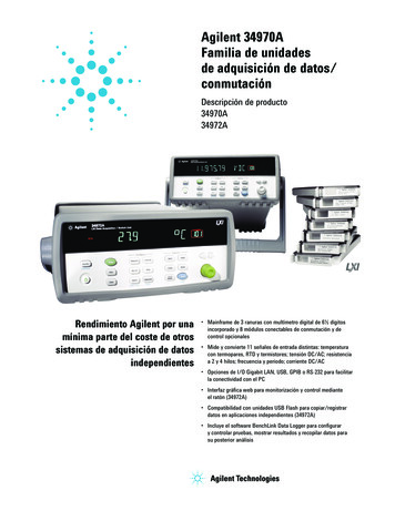
34970A Refresh SG.book Page 5 Thursday, February 4, 2010 11:16 AMNote: Unless otherwise indicated, this manual applies to all serial numbers.The Agilent Technologies 34970A/34972A combines precisionmeasurement capability with flexible signal connections for yourproduction and development test systems. Three module slots are builtinto the rear of the instrument to accept any combination of dataacquisition or switching modules. The combination of data logging anddata acquisition features makes this instrument a versatile solution foryour testing requirements now and in the future.Convenient Data Logging Features Direct measurement of thermocouples, RTDs, thermistors, DCvoltage, AC voltage, resistance, DC current, AC current, frequency,and period Interval scanning with storage of up to 50,000 time-stamped readings Independent channel configuration with function, Mx B scaling, andalarm limits available on a per-channel basis Intuitive user interface with knob for quick channel selection, menunavigation, and data entry from the front panel Portable, ruggedized case with non-skid feet BenchLink Data Logger 3 Software for Microsoft Windows includedFlexible Data Acquisition/Switching Features 6½-digit multimeter accuracy, stability, and noise rejection Up to 60 channels per instrument (120 single-ended channels) Reading rates up to 500 readings per second on a single channel andscan rates up to 250 channels per second Choice of multiplexing, matrix, general-purpose Form C switching,RF switching, digital I/O, totalize, and 16-bit analog output functions GPIB (IEEE-488) interface and RS-232 interface are standard on the34970A. Local Area Network (LAN) and Universal Serial Bus (USB)are standard on the 34972A. SCPI (Standard Commands for Programmable Instruments)compatibilityAgilent 34970A/34972AData Acquisition/Switch Unit
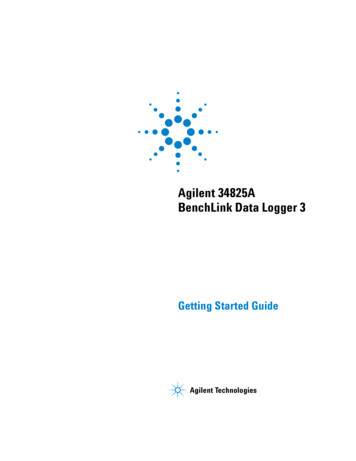
34970A Refresh SG.book Page 6 Thursday, February 4, 2010 11:16 AMThe Front Panel at a GlanceDenotes a menu key. See the next page for details on menu operation.12345676State Storage / Remote Interface MenusScan Start / Stop KeyMeasurement Configuration MenuScaling Configuration MenuAlarm / Alarm Output Configuration MenuScan-to-Scan Interval MenuScan List Single Step / Read Key8 Advanced Measurement / Utility Menus9 Low-Level Module Control Keys10 Single-Channel Monitor On / Off Key11 View Scanned Data, Alarms, Errors Menu12 Shift / Local Key13 Knob14 Navigation Arrow Keys
34970A Refresh SG.book Page 7 Thursday, February 4, 2010 11:16 AMThe Front-Panel Menu at aGlanceSeveral of the front-panel keys guide youthrough menus to configure variousparameters of the instrument (see previouspage). The following steps demonstrate themenu structure using thekey.41. Press the menu key. You areautomatically guided to the first level ofthe menu. Rotate the knob to view theother choices on the first level of themenu.The menu will automatically time out afterabout 20 seconds of inactivity. You will bereturned to the operation in progress priorto entering the menu.2. Press the same menu key again to move tothe next item of the menu. Typically, thisis where you choose parameter values forthe selected operation.3. Rotate the knob to view the choices on thislevel of the menu. When you reach the endof the list, rotate the knob in the oppositedirection to view all of the other choices.The current selection is highlighted foremphasis. All other choices are dimmed.4. Press the same menu key again to acceptthe change and exit the menu. A briefconfirmation message is displayed.Tip: To review the current configuration of a specific menu, press the menu key several times.A message NO CHANGES is displayed when you exit the menu.7
34970A Refresh SG.book Page 8 Thursday, February 4, 2010 11:16 AMDisplay M (34970A)MEM (34972A)AUTO (34972A)LASTMINMAXSHIFT4WOCScan is in progress or enabled. Press and holdagain to turn off.Monitor mode is enabled. Pressagain to turn off.Scanned readings, alarms, errors, or relay cycles are being viewed.Channel configuration is in progress on displayed channel.Measurement is in progress.Instrument is addressed to listen or talk over the remote interface.Instrument is in remote mode (remote interface).Hardware or remote interface errors are detected. Pressto read errors.Instrument is configured for an external scan interval.Scan Once mode is enabled. Pressto initiate and hold key to disable.Reading memory overflow; new readings will overwrite the oldest readings.A USB drive is connected to the instrument (annunciator on), or data isbeing written to or read from the USB drive (annunciator flashing).USB logging is active.Viewed data is the last reading stored during most recent scan.Viewed data is the minimum reading stored during most recent scan.Viewed data is the maximum reading stored during most recent scan.has been pressed. Pressagain to turn off.4-wire function is in use on displayed channel.Offset compensation is enabled on displayed channel.Alarms are enabled on displayed channel.Mx B scaling is enabled on displayed channel.HI or LO alarm condition has occurred on indicated alarms.To review the display annunciators, hold down theas you turn on the instrument.8key
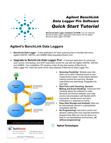
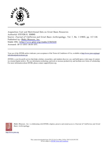
34970A Refresh SG.book Page 9 Thursday, February 4, 2010 11:16 AMThe 34970A Rear Panel at a Glance41 Slot Identifier (100,200, 300)2 Ext Trig Input / Alarm Outputs / ChannelAdvance Input / Channel Closed Output3 RS-232 Interface Connector4567Power-Line Fuse-Holder AssemblyPower-Line Voltage SettingChassis Ground ScrewGPIB (IEEE-488) Interface ConnectorUse theMenu to: Select the GPIB or RS-232 interface (see chapter 2). Set the GPIB address (see chapter 2). Set the RS-232 baud rate, parity, and flow control mode (see chapter 2).WARNINGFor protection from electrical shock, the power cord ground must not bedefeated. If only a two-contact electrical outlet is available, connect theinstrument’s chassis ground screw (see above) to a good earth ground.9
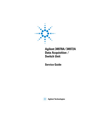
34970A Refresh SG.book Page 10 Thursday, February 4, 2010 11:16 AMThe 34972A Rear Panel at a Glance ExtT rig / Alarms (5V)US168520ICES/NMB-001ISM-A1LXI Class CLine: 50/60/400 Hz100V 120V (127V)240V 220V (230V)N10149Fuse: 500mAT(250V)Opt. 00130 V A Max1 Slot Identifier (100,200, 300)2 Chassis Ground Screw3 Ext Trig Input / Alarm Outputs / ChannelAdvance Input / Channel Closed Output4567LANHostDevice Power-Line Fuse-Holder AssemblyLAN ConnectorUSB Drive ConnectorUSB Interface ConnectorUse theMenu to: Select and configure the LAN and USB interfaces (see chapter 2).For protection from electrical shock, the power cord ground must not bedefeated. If only a two-contact electrical outlet is available, connect theinstrument’s chassis ground screw (see above) to a good earth ground.WARNING10
34970A Refresh SG.book Page 11 Thursday, February 4, 2010 11:16 AMThe Plug-In Modules at a GlanceFor complete specifications on each plug-in modules, refer to the modulesections in chapter 8.34901A 20-Channel Armature Multiplexer 20 channels of 300 V switching Two channels for DC or AC current measurements (100 nA to 1A)4 Built-in thermocouple reference junction Switching speed of up to 60 channels per second Connects to the internal multimeter For detailed information and a module diagram, see page 152.Each of the 20 channels switches both HI and LO inputs, thus providingfully isolated inputs to the internal multimeter. The module is dividedinto two banks of 10 two-wire channels each. When making four-wireresistance measurements, channels from Bank A are automaticallypaired with channels from Bank B. Two additional fused channels areincluded on the module (22 channels total) for making calibrated DC orAC current measurements with the internal multimeter (external shuntresistors are not required). You can close multiple channels on thismodule only if you have not configured any channels to be part of thescan list. Otherwise, all channels on the module are break-before-make.34902A 16-Channel Reed Multiplexer 16 channels of 300 V switching Built-in thermocouple reference junction Switching speed of up to 250 channels per second Connects to the internal multimeter For detailed information and a module diagram, see page 154.Use this module for high-speed scanning and high-throughputautomated test applications. Each of the 16 channels switches both HIand LO inputs, thus providing fully isolated inputs to the internalmultimeter. The module is divided into two banks of eight two-wirechannels each. When making four-wire resistance measurements,channels from Bank A are automatically paired with channels from BankB. You can close multiple channels on this module only if you have notconfigured any channels to be part of the scan list. Otherwise, allchannels on the module are break-before-make.11
34970A Refresh SG.book Page 12 Thursday, February 4, 2010 11:16 AM34903A20-Channel Actuator / General-Purpose Switch 300 V, 1 A actuation and switching SPDT (Form C) latching relays Breadboard area for custom circuits For detailed information and a module diagram, see page 156.Use this module for those applications that require high-integritycontacts or quality connections of non-multiplexed signals. This modulecan switch 300 V, 1 A (50 W maximum switch power) to your deviceunder test or to actuate external devices. Screw terminals on the moduleprovide access to the Normally-Open, Normally-Closed, and Commoncontacts for each of the 20 switches. A breadboard area is provided nearthe screw terminals to implement custom circuitry, such as simplefilters, snubbers, or voltage dividers.34904A 4x8 Two-Wire Matrix Switch 32 two-wire crosspoints Any combination of inputs and outputs can be connected at a time 300 V, 1 A switching For detailed information and a module diagram, see page 157.Use this module to connect multiple instruments to multiple points onyour device under test at the same time. You can connect rows andcolumns between multiple modules to build larger matrices such as 8x8and 4x16, with up to 96 crosspoints in a single mainframe.34905/6A Dual 4-Channel RF Multiplexers 34905A (50 ) / 34906A (75 ) 2 GHz bandwidth with on-board SMB connections 1 GHz bandwidth with SMB-to-BNC adapter cables provided For detailed information and a module diagram, see page 158.These modules offer wideband switching capabilities for high frequencyand pulsed signals. Each module is organized in two independent banksof 4-to-1 multiplexers. Both modules offer low crosstalk and excellentinsertion loss performance. To create larger RF multiplexers, you cancascade multiple banks together. Only one channel in each bank may beclosed at a time.12
34970A Refresh SG.book Page 13 Thursday, February 4, 2010 11:16 AM34907A Multifunction Module Two 8-bit Digital Input/Output ports, 400 mA sink, 42 V opencollector 100 kHz Totalize input with 1 Vpp sensitivity Two 16-bit, 12 V Calibrated Analog Outputs For detailed information and module block diagrams, see page 161.Use this module to sense status and control external devices such assolenoids, power relays, and microwave switches. For greater flexibility,you can read digital inputs and the count on the totalizer during a scan.434908A 40-Channel Single-Ended Multiplexer 40 channels of 300 V single-ended (common LO) switching Built-in thermocouple reference junction Switching speed of up to 60 channels per second Connects to the internal multimeter For detailed information and a module diagram, see page 159.Use this module for high-density switching applications which requiresingle-wire inputs with a common LO. All relays are break-before-maketo ensure that only one relay is connected at any time.13
34970A Refresh SG.b
navigation, and data entry from the front panel Portable, ruggedized case with non-skid feet BenchLink Data Logger 3 Software for Microsoft Windows included Flexible Data Acquisition/Switching Features 6½-digit multimeter accuracy, stability, and noise rejection Up