Transcription
Data Acquisition UnitVersion 3.10User ManualCourtenay House, Monument Way East, Woking, Surrey GU21 5LY, U.K.Tel: 44-1483-750600 Fax: 44-1483-762233Email: support@medcotas.comHome Page: http://www.medcotas.com
Table of ContentsSystem Overview. 3Installation. 4Displays . 5Communications . 7S0 . 9S1 . 9S2 . 9Communicating through HyperTerminal. 10Command. 10Explanation . 10Calibrating Channels. 11Serial Cables . 12Card Data Reader . 13Overview. 13Installation . 13Using the program. 13Important Information about Storing Data . 14Preparing the card for new data . 14Moving data to database files on the computer . 14Wiring Diagram for Acquisition Unit. 17Appendix – A: Coiled Tubing Applications . 18Shaft Encoder. 19Specifications:. 19Connectors for Shaft Encoder Cable: . 19Pressure Sensors . 21Electrical Connection for Pressure Sensors:. 21Proximity Switch . 24Specifications:. 24Electrical Connection for Proximity Switch:. 24Magnetic Pickup . 24Electrical Connection for Magnetic Pickup:. 25Adaptor for Magnetic Pickup: . 25Cable for Proximity Switch/Magnetic Pickup to Data Collection Unit: . 26Connectors on Cable for Proximity Switch/Magnetic Pickup:. 262
System OverviewThe system is based on a microprocessor controller with a Motorola 68000 14 MHz processor as themain controller. Analogue and counter signals are acquired and processed. The data is stored,processed, and transmitted.There are provisions for 8-8 bits and 8-12 bits analogue signals on the microprocessor board.However, the MEDCO data acquisition system only uses 8-12 bits channels. An additional board isutilised for the counter and quadrature signals. Provisions are for 4 counters and 1 quadrature shaftencoder, all of which can be used.Provisions are also made for storing number formats, gain, and offset values, lower and upper alarmvalues for all the input channels. This information is used for the processing of the data and theoutputs. Furthermore, rates are computed for all the counters and the quadrature signals.Three serial communication ports are provided. Currently, these are used for communicating withdisplays and the computer. The third port is used for storing data on a S-RAM PC-MCIA card with acapacity of 6 MByte.3
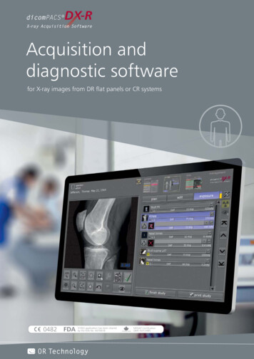
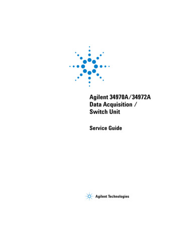
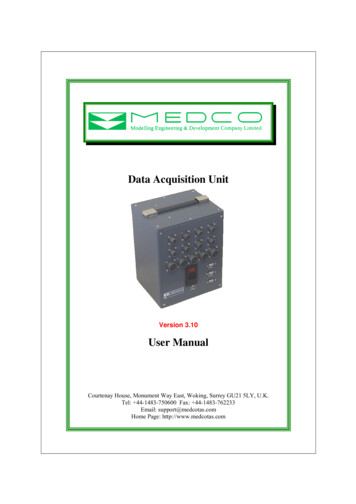
InstallationInstallation of the system is very simple and straightforward. The following steps should enable theuser to use the system. Get the data acquisition unit out of the packaging. Mechanically attach the sensors to your equipment. For coiled tubing equipment, therecommended attachments are described in Appendix – A. Connect the sensors to the data acquisition unit. All the analogue sensors are to be connectedto the analogue channels, i.e. circulating pressure, wellhead pressure, and weight to any of theanalogue channels 1 through to 8. Proximity switches are to be connected to any channel from9 to 12 and finally shaft encoder to be connected to channel 13. Connect to a mains power supply. The mains power supply is strictly what you ordered, i.e. ifyou ordered 220 VAC then you should only use 220-250 VAC, and if you ordered 110 VACthen you should only use 110-125 VAC. Alternatively, if you have a DC power then you mayuse the Auxiliary power supply and connect it to 24 VDC. You can make 24 VDC powersupply using two car-batteries in series. Connect your displays (supplied by MEDCO) to the serial port S0 using the serial link cablesupplied by MEDCO. The displays require power either as 220 VAC, 110 VAC, or 5 VDC. Switch on the Data Acquisition Unit. If you do not have a computer ready for the data acquisition, then the system willautomatically start in just over 1 minute. If you have a computer ready to acquire data, then connect the computer using the suppliedserial cable to the serial port S1. You should have a program capable of communicatingthrough the serial port running on the computer, such as DART or HyperTerminal. Thesystem will wait for one minute before starting. The system will now be running with all the factory default settings. The factory defaults are again of unity and an offset value of zero for all the channels. All alarms are switched off.Figure 1: Front view of the data acquisition unit – measures 23 x 20 x 16 cms (Part No. 10005)4
Figure 1, shows the front side of the unit. This side has all the connections. Note the channel numbersindicated on the picture. The channels are 1 through to 13 and increment from left to right and top tobottom. The serial ports are also numbered as S0 through to S2 (from top to bottom).The configuration of the system is as follows:Channelnumber1 to 8Sensor typeComments24 vdc excitation voltage.12-bits resolution.9 to 12Analogue giving 0-10 vdc output or 0-5 vdc**Pressure sensors, load cells, density meters, or anyanalogue signal.Proximity switch or magnetic pick-up13Quadrature shaft encoder14 to 17No connections18No connections12 vdc excitation voltage.Received pulses are conditionedto be TTL compatible.5 vdc excitation voltage.Up/down counter.Rates of channels 9-12respectively.Rate of channel 13.**The analogue channels inputs vary depending on the user choice of sensors. You should consult withMEDCO if you need to know what voltage range is acceptable to your system.DisplaysIt is important to note that , the displays use the same system for numbering as the data acquisitionunit, though the numbers appear in hexadecimals. The displays use address 00 for all displays torespond to data, then addresses 01 (corresponds to address 1 in decimal) through to ff in hexadecimal(corresponds to address 255 in decimal). Thus, to program a display to receive a signal from the dataacquisition unit, the display address should match the channel number.To change the address of a display:a. Move the flip switch number 3 to the OFF position to unlock the display, on the 2nd block offlip switches from the left-hand-side. (See the rear view figure).b. On the front of the display unit, press and hold the address button until the address of thedisplay unit appears.c. Change the address using the up Δ or down button to increment or decrement the displayaddress until the required address is shown (in hexadecimal).d. Press the OK button to accept.e. Move the flip switch back to the locked position (ON), i.e. reverse step (a) above.Example:Suppose you have three displays and you wish to use them to display the counts of channel 9, the valueof channel 6, and the rate of channel 10 (corresponds to channel 15), then the displays should beconfigured with the addresses 09, 06, and 0F respectively.HINT: If you have difficulties converting decimal numbers to hexadecimal then use “Calculator” onyour computer to do the conversions for you. Enter the channel number in decimal then select the hexoption and the equivalent hexadecimal will be displayed. If the value is a one digit hexadecimal, thensimply add a zero to the left. Alternatively, simply count (in decimals) as you increment the address onthe display.5
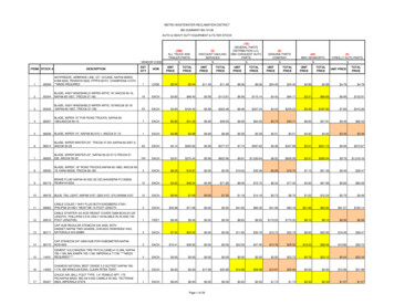
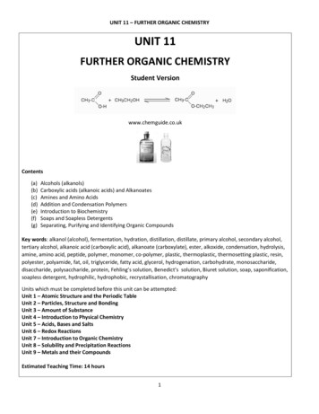
Rear view of display unitINPUTPOWEREarthRear of display panelNeutral or DCLive or DC 45932716Wiring diagram of display unit connection to D-type connectorFront view of display unit (Part No. 06003)6
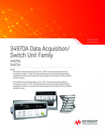
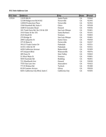
MEDCO’s LED DisplaysLED Display:Enclosure (3 displays):Part Number 17001Part Number 17002Menu buttonUp buttonDown button3-LED Displays ModuleOn each display the buttons assignment is as follows:Left button is MENU BUTTONMiddle button is UP BUTTONRight button is DOWN BUTTONEach LED display can have an address between 1 to 255 (in hexadecimal, i.e. 00 to FF). When thedisplay address corresponds to a channel address on the data acquisition unit, the display will show thevalue of the parameter associated with the channel. The channels are numbered 1 through to 18 indecimals.SpecificationsThe displays operate on a 12 vdc power supply and in RS-485 mode and have the following protocolsettings: BAUD RATE: Either 9600 or 19200. When going through the menu, a baud rate of 9600 willbe shown as BAUD00 while a baud rate of 19200 will be shown as BAUD01. PARITY: None. DATA BITS: 8 STOP BIT: 1When used with the Data Acquisition unit, the baud rate needs to be set to 9600 (BAUD00).7
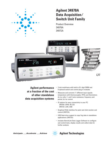
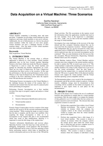
Changing Display SettingsTo change the settings on the display, press and hold the Menu Button for at least 2 seconds, thedisplay will show the current baud rate setting, use the Up Button or the Down Button to change thesettings if required.To see the next menu item, press the Menu Button again, the display will show the current address ishexadecimals (i.e. 00 to FF). Use the Up Button to increment and the Down Button to decrement theaddress to the value desired.Finally, press the Menu Button again to go to the next menu item, SAVE. Press the Up Button to savethe settings.Wiring DiagramsPower ConnectorsData ConnectorsOUT - SOCKETOUT - SOCKETIN - PLUG 12 vdcData signals A & B126374859549IN - PLUG382114672Signal common3Looking inside the enclosure panelNote: Wire colours may be different from those shown81432
CommunicationsAll the communications with the data acquisition unit are achieved through the serial ports. These portsare assigned specific tasks and cannot swapped or changed.S0The first serial port, S0, is used for communication with the displays. A serial link cable is supplied foruse with this port. The port is configured in RS-485 mode. The port configuration is as follows:Baud rate:Data bits:Parity:Stop bits:Handshake:96008None1NoneS1The second serial port, S1, is used for communication with the computer. A serial link cable, supplied,suitable for connecting to this port on one end (male side) and fitted with a female side for connectingto the computer. This port is configured in RS-232 mode. This port is configured as follows:Baud rate:Data bits:Parity:Stop bits:Handshake:192008None1Hardware (RTS/CTS)Note that the handshake configuration is RTS/CTS. Thus, if you connect this to a computer, you mustrun a communications program on the computer and configure the handshake as HARDWARE.The user may use any program to capture the data. DART (Data Acquisition and Real Time processingby MEDCO) is the recommended software to use with the data acquisition unit. DART is capable ofauto-detecting the unit and has several features that make communicating with the unit simple.Alternatively, you may use a program such as Hyperterminal to communicate with the data acquisitionunit. To do this, follow these steps: From your windows START button click PROGRAMS ACCESSORIES COMMUNICATIONS HYPERTERMINAL. Double click the Hypertrm icon. Give the session a name such as “MEDCO’s data acquisition unit”. On the next screen use “CONNECT USING” and specify the appropriate com port, exampleCOM1. On the next screen titled “PORT SETTINGS”, ensure that the bits per second is set to 19200and the “FLOW CONTROL” is set to HARDWARE. Allow a minute and then you should see the data coming from the data acquisition unit.Alternatively, type the letter “q” in lower case and the system should start.S2The third serial port, S2 (RS-232 mode), can be used to write data to an S-
Data Acquisition Unit Version 3.10 User Manual Courtenay House, Monument Way East, Woking, Surrey GU21 5LY, U.K. Tel: 44-1483-750600 Fax: 44-1483-762233