Transcription
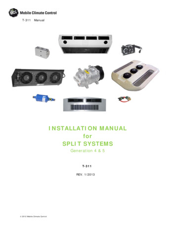
T-311ManualINSTALLATION MANUALforSPLIT SYSTEMSGeneration 4 & 5T-311REV. 1/2013 2012 Mobile Climate Control
SAFETY SUMMARYGENERAL SAFETY NOTICESThe following general safety notices supplement the specific warnings and cautions appearing elsewhere in thismanual. They are recommended precautions that must be understood and applied during installation,operation, service, and maintenance of the equipment covered herein. The general safety notices are presentedin the following three sections labeled: First Aid, Operating Precautions and Installation Precautions. A listingof the specific warnings and cautions appearing elsewhere in the manual follows the general safety notices.FIRST AIDAn injury, no matter how slight, should never go unattended. Always obtain first aid or medical attentionimmediately.OPERATING PRECAUTIONSAlways wear protective eye wear (safety glasses or goggles).Keep hands, clothing and tools clear of the evaporator and condenser fans.No work should be performed on the system unless battery power is disconnected.Always work in pairs. Never work on the equipment alone.In case of severe vibration or unusual noise, stop the system and investigate.When vehicle engine is running, keep your hands, clothing and tools clear of the engine fan blade and drive belts.INSTALLATION PRECAUTIONSFamiliarize yourself with the proper operation of any service equipment you will be using (voltmeter, ampprobe, manifold gauges, etc.). Always read the owner's manual that is enclosed with the equipmentAlways follow the manufacturers instructions for your recovery/recycling equipment. Failure to do so couldcause personal injury or damage to your equipment. Never perform any maintenance or service on yourequipment before consulting with authorized service personnel. Always unplug unit before attempting anymaintenance. Removing internal fittings and filters can release pressurized refrigerant. Slowly release pressureand always wear appropriate safety wear.Avoid breathing any refrigerant vapor, lubricant vapor, or mist. Exposure to these, particularly PAG oil mist,may irritate your eyes, nose, or throat.Always use a DOT (Department of Transportation) approved cylinder for storing used and recycledrefrigerant. Approved cylinders will be stamped DOT 4BW or DOT 4BA. MCC recommends a MACS (MobileAir Conditioning Society) certification in Recovery/Recycling to gain more information on handling and usingrefrigerants.Never attempt to apply heat or open flame to a refrigerant cylinder. High temperatures can raise the cylinderpressure to dangerous levels. MCC recommends using a heat blanket to increase the internal temperature of therefrigerant cylinder, greatly increasing the rate of transfer of refrigerant to the bus air conditioning system.Never use compressed air (shop-air) to leak-test or pressure test a R134a system. Under certain conditions,pressurized mixtures of R134a and air can be combustible. In addition, shop air will inject moisture into thesystem.Always use mineral oil to lubricate “O” Rings, hoses and fittings on R134a systems. PAG oils will absorbmoisture and become very acidic and corrosive. Mineral oil will not absorb moisture and thus preventcorrosion. Always wear gloves when working with PAG and Ester lubricants to prevent irritation to your skin.R134a lubricants can also damage vehicles paint, plastic parts, engine drive belts and coolant hoses.Beware of unannounced starting of the evaporator and condenser fans. Do not remove the evaporator cover orcondenser fan guards without disconnecting the vehicle battery cable. 2012 Mobile Climate ControlSafety --iT-311 Rev. 1/2013
Always wear gloves when handling evaporators and condensers.Be sure power is turned off before working on motors, controllers, and electrical control switches. Tag systemcontrols and vehicle battery to prevent accidental energizing of the system.Do not bypass any electrical safety devices, e.g. bridging an overload, or using any sort of jumper wires.Problems with the system should be diagnosed, and any necessary repairs performed, by qualified servicepersonnel.When performing any arc welding on the vehicle, disconnect the vehicle battery.In case of electrical fire, extinguish with CO2 (never use water). Disconnect vehicle battery power if possible.Never route hoses or electrical harnesses down the front of the bus on the driver's side when installing a frontmounted evaporator assembly. Driver visibility could be impaired.Before drilling holes for routing hoses and harnesses through the bus floor or wall, make sure there are noelectrical harnesses, floor braces, tubing, etc. in the path of the holes to be drilled. Drilling into an electricalharness or fuel line could cause a fire or explosion.SPECIFIC WARNINGS AND CAUTIONSWARNINGDo not attempt to modify the EM-3 evaporator top panel. Modifications to the top panel couldstructurally weaken the evaporator assembly, causing system failures and/or injuries to pas sengers.WARNINGDo not use a nitrogen cylinder without a pressure regulatorWARNINGNever use air for leak testing. It has been determined that pressurized, air-rich mixtures of re frigerants and air can undergo combustion when exposed to an ignition source.CAUTIONWhen installing a GEN-5 evaporator assembly, never push against the blower wheel. It can eas ily be knocked out of balance. Hold unit up to the ceiling with the evaporator framing, not theblower wheel.CAUTIONFailure to seal these noise abatement headliners (perforated) will allow dissipation of the airand marginal cooling. 2012 Mobile Climate ControlSafety --iiT-311 Rev. 1/2013
CAUTIONUse of substitute hardware or failure to follow the installation instructions may result in struc tural fatigue and/or breakage.CAUTIONWhen installing any GEN 5 Evaporator assembly, be very careful not to push against the blowerwheel (s). The blower wheel can easily be distorted and will have to be replaced.CAUTIONWhen selecting a location for installing the evaporator it is highly recommended that two roofbows are used to secure the mounting rails.CAUTIONWhen installing any IW unit, be careful not to cut the bus structure rails or wiring harnesses.CAUTIONBecause of the limited access to the block valve, start the fittings by hand (finger tightening)making sure that there is no cross-threading before tightening. When tightening the fittings,make sure that the Block Valve does not move.CAUTIONNever route refrigerant hose, electrical cable or drain lines in any location where driver's visibal ity would be impaired.CAUTIONWhen marking the cut-out for a front mounted In-Wall be very careful not to cut too much offthe top radii.CAUTIONWhen removing any electrical item involving multiple plugs/sockets it is recommended thatyou mark both sides of the plug/socket arrangement. This way you will not have to guess whatgoes where when re-connecting. 2012 Mobile Climate ControlSafety --iiiT-311 Rev. 1/2013
CAUTIONBecause of the limited access to the block valve, start the fittings by hand (finger tightening)making sure that there is no cross-threading before tightening. When tightening the fittings,make sure that the Block Valve does not move.CAUTIONNever tie-wrap or secure in any way, refrigerant hose or electrical cable to any part that maymove during the normal operation of the vehicle. Always use insulated clamps to secure to thebus wall.CAUTIONMake sure there is nothing installed where you are going to drill through the bus floor.CAUTIONThe Rooftop Condenser assembly must contact the bus roof in the center. If not, damage willoccur. Consult factory as optional mounting may be required.CAUTIONAll 3/16 and 1/4 In. rivet engagement thickness (grip range) must be between 0.080 and 0.625.Using rivets other than those specified may allow the condenser assembly to come loose fromthe bus roof.CAUTIONCondenser assemblies must be properly installed using graded hardware. The CM-2 condenserassembly requires at least 4 bolts and the CM-3 requires at least 6 bolts.CAUTIONWhen drilling into the vehicle wall, always use a drill stop to help protect against damaging anywiring that might be located behind the wall.CAUTIONNever substitute fittings or hose. Follow the piping diagram provided with the system. 2012 Mobile Climate ControlSafety --ivT-311 Rev. 1/2013
CAUTIONNever substitute fittings or hose. Follow the piping diagram provided with the system.CAUTIONNo matter what type of lubricant (oil) used in the system, always use mineral oil to lubricate theO-Rings, and fittings. PAG oils will absorb moisture and become very acidic and corrosive.Mineral oil will not absorb moisture and thus prevent corrosion.CAUTIONAlways use existing holes in the chassis frame. Never drill holes in the chassis frame.CAUTIONTie-Wraps may be used to bundle hoses and harnesses, but should never be used to securehoses to the vehicle.CAUTIONVerify that the oil added to the air conditioning system is the same oil that is in the compressor.The mixing of incompatible oils will damage your system. 2012 Mobile Climate ControlSafety --vT-311 Rev. 1/2013
TABLE OF CONTENTSSection . . . . . . . . . . . . . . . . . . . . . . . . . . . . . . . . . . . . . . . . . . . . . . . . . . . . . . . . . . . . . . . . . . . . . . . . . . . . . . . . . . . . . . . PageDESCRIPTION . . . . . . . . . . . . . . . . . . . . . . . . . . . . . . . . . . . . . . . . . . . . . . . . . . . . . . . . . . . . . . . . . . . .1.1 INTRODUCTION . . . . . . . . . . . . . . . . . . . . . . . . . . . . . . . . . . . . . . . . . . . . . . . . . . . . . . .1.2 WHAT IS AIR CONDITIONING . . . . . . . . . . . . . . . . . . . . . . . . . . . . . . . . . . . . . . . . . . .1.3 SYSTEM NOMENCLATURE DESIGNATIONS . . . . . . . . . . . . . . . . . . . . . . . . . . . . . . .1.3.11.3.21-11-11-11-1Model And Serial Number Tags . . . . . . . . . . . . . . . . . . . . . . . . . . . . . . . . . . . . . . . . . . . . . . . . . . . . . . . .System Requirements Label . . . . . . . . . . . . . . . . . . . . . . . . . . . . . . . . . . . . . . . . . . . . . . . . . . . . . . . . . . .1-11-11.4 SYSTEM COMPONENTS . . . . . . . . . . . . . . . . . . . . . . . . . . . . . . . . . . . . . . . . . . . . . . . . .1.5 COOLING CYCLE . . . . . . . . . . . . . . . . . . . . . . . . . . . . . . . . . . . . . . . . . . . . . . . . . . . . . . .1.6 EVAPORATORS . . . . . . . . . . . . . . . . . . . . . . . . . . . . . . . . . . . . . . . . . . . . . . . . . . . . . . . .1.7 CONDENSERS . . . . . . . . . . . . . . . . . . . . . . . . . . . . . . . . . . . . . . . . . . . . . . . . . . . . . . . . .1.8 PRE-INSTALLATION INSPECTION . . . . . . . . . . . . . . . . . . . . . . . . . . . . . . . . . . . . . . .EVAPORATORS . . . . . . . . . . . . . . . . . . . . . . . . . . . . . . . . . . . . . . . . . . . . . . . . . . . . . . . . . . . . . . . . . . . .2.1 INTRODUCTION . . . . . . . . . . . . . . . . . . . . . . . . . . . . . . . . . . . . . . . . . . . . . . . . . . . . . . n . . . . . . . . . . . . . . . . . . . . . . . . . . . . . . . . . . . . . . . . . . . . . . . . . . . . . . . . . . . . . . . . . . . . . . . .Location . . . . . . . . . . . . . . . . . . . . . . . . . . . . . . . . . . . . . . . . . . . . . . . . . . . . . . . . . . . . . . . . . . . . . . . . . .Cap Plugs . . . . . . . . . . . . . . . . . . . . . . . . . . . . . . . . . . . . . . . . . . . . . . . . . . . . . . . . . . . . . . . . . . . . . . . . .Blower Wheels . . . . . . . . . . . . . . . . . . . . . . . . . . . . . . . . . . . . . . . . . . . . . . . . . . . . . . . . . . . . . . . . . . . . .Aesthetics . . . . . . . . . . . . . . . . . . . . . . . . . . . . . . . . . . . . . . . . . . . . . . . . . . . . . . . . . . . . . . . . . . . . . . . . .Mounting (Front & Rear) . . . . . . . . . . . . . . . . . . . . . . . . . . . . . . . . . . . . . . . . . . . . . . . . . . . . . . . . . . . . .Mounting (Side) . . . . . . . . . . . . . . . . . . . . . . . . . . . . . . . . . . . . . . . . . . . . . . . . . . . . . . . . . . . . . . . . . . . .In-Wall Evaporators . . . . . . . . . . . . . . . . . . . . . . . . . . . . . . . . . . . . . . . . . . . . . . . . . . . . . . . . . . . . . . . . .Drain Lines . . . . . . . . . . . . . . . . . . . . . . . . . . . . . . . . . . . . . . . . . . . . . . . . . . . . . . . . . . . . . . . . . . . . . . . .Ducted Systems . . . . . . . . . . . . . . . . . . . . . . . . . . . . . . . . . . . . . . . . . . . . . . . . . . . . . . . . . . . . . . . . . . . .Bus Headliners . . . . . . . . . . . . . . . . . . . . . . . . . . . . . . . . . . . . . . . . . . . . . . . . . . . . . . . . . . . . . . . . . . . . .Mounting Hardware . . . . . . . . . . . . . . . . . . . . . . . . . . . . . . . . . . . . . . . . . . . . . . . . . . . . . . . . . . . . . . . . .2-12-12-12-12-12-12-12-12-12-12-12-2REAR MOUNTED EVAPORATORS . . . . . . . . . . . . . . . . . . . . . . . . . . . . . . . . . . . . . . . .2-22.2.12.2.22.2.32.32.42.52.6GEN 4/5 Series EM-1, EM-2, EM-3, EM-7, EM-6, & EM-14 . . . . . . . . . . . . . . . . . . . . . . . . . . . . . . . .Luggage Compartment Evaporator . . . . . . . . . . . . . . . . . . . . . . . . . . . . . . . . . . . . . . . . . . . . . . . . . . . . . .EM-3 EVAPORATOR GEN 4 OR GEN 5 . . . . . . . . . . . . . . . . . . . . . . . . . . . . . . . . . . . . . . . . . . . . . .2-22-102-11SIDE MOUNTED EVAPORATOR - EM-1, EM-2, EM-6, EM-7, & EM-14 . . . . . . . . . .EM-9 DUCTED EVAPORATOR . . . . . . . . . . . . . . . . . . . . . . . . . . . . . . . . . . . . . . . . . . .EM-17 EVAPORATOR . . . . . . . . . . . . . . . . . . . . . . . . . . . . . . . . . . . . . . . . . . . . . . . . . . .IW-1, IW-2, & IW-14 EVAPORATORS . . . . . . . . . . . . . . . . . . . . . . . . . . . . . . . . . . . . . . .2-122-162-192-202.6.12.6.22.6.3Rear Mounted In-Wall Evaporator . . . . . . . . . . . . . . . . . . . . . . . . . . . . . . . . . . . . . . . . . . . . . . . . . . . . . .Front Mounted In-Wall Evaporator . . . . . . . . . . . . . . . . . . . . . . . . . . . . . . . . . . . . . . . . . . . . . . . . . . . . .In-Wall Evaporator - TBB . . . . . . . . . . . . . . . . . . . . . . . . . . . . . . . . . . . . . . . . . . . . . . . . . . . . . . . . . . . .2-202-262-302.7 EM-20, EM-21 & EM-22 EVAPORATORS . . . . . . . . . . . . . . . . . . . . . . . . . . . . . . . . . . . .2.8 EM-23 COOL/HEAT EVAPORATOR . . . . . . . . . . . . . . . . . . . . . . . . . . . . . . . . . . . . . . .CONDENSERS . . . . . . . . . . . . . . . . . . . . . . . . . . . . . . . . . . . . . . . . . . . . . . . . . . . . . . . . . . . . . . . . . . . .3.1 INTRODUCTION . . . . . . . . . . . . . . . . . . . . . . . . . . . . . . . . . . . . . . . . . . . . . . . . . . . . . . .2-312-313-13-1 2012 Mobile Climate ControliT-311 Rev. 1/2013
3Description . . . . . . . . . . . . . . . . . . . . . . . . . . . . . . . . . . . . . . . . . . . . . . . . . . . . . . . . . . . . . . . . . . . . . . . .Location . . . . . . . . . . . . . . . . . . . . . . . . . . . . . . . . . . . . . . . . . . . . . . . . . . . . . . . . . . . . . . . . . . . . . . . . . .Cap Plugs . . . . . . . . . . . . . . . . . . . . . . . . . . . . . . . . . . . . . . . . . . . . . . . . . . . . . . . . . . . . . . . . . . . . . . . . .Protection . . . . . . . . . . . . . . . . . . . . . . . . . . . . . . . . . . . . . . . . . . . . . . . . . . . . . . . . . . . . . . . . . . . . . . . . .Obstructions . . . . . . . . . . . . . . . . . . . . . . . . . . . . . . . . . . . . . . . . . . . . . . . . . . . . . . . . . . . . . . . . . . . . . . .Skirt Supports . . . . . . . . . . . . . . . . . . . . . . . . . . . . . . . . . . . . . . . . . . . . . . . . . . . . . . . . . . . . . . . . . . . . . .Mounting (Skirt) . . . . . . . . . . . . . . . . . . . . . . . . . . . . . . . . . . . . . . . . . . . . . . . . . . . . . . . . . . . . . . . . . . . .Mounting (Rooftop) . . . . . . . . . . . . . . . . . . . . . . . . . . . . . . . . . . . . . . . . . . . . . . . . . . . . . . . . . . . . . . . . .Voltage . . . . . . . . . . . . . . . . . . . . . . . . . . . . . . . . . . . . . . . . . . . . . . . . . . . . . . . . . . . . . . . . . . . . . . . . . . .3-13-13-13-13-13-13-13-13-1CONDENSERS . . . . . . . . . . . . . . . . . . . . . . . . . . . . . . . . . . . . . . . . . . . . . . . . . . . . . . . . .CM-2, CM-3, CM-4, CM-5, & CM-14 SKIRTMOUNTED CONDENSER ASSEMBLIES3-23-23.3.13.43.5SKIRT-MOUNTED INSTALLATIONS . . . . . . . . . . . . . . . . . . . . . . . . . . . . . . . . . . . . . . . . . . . . . . . .3-2CM-5 CONDENSER . . . . . . . . . . . . . . . . . . . . . . . . . . . . . . . . . . . . . . . . . . . . . . . . . . . . .KR-4 ROOFTOP CONDENSER ASSEMBLY . . . . . . . . . . . . . . . . . . . . . . . . . . . . . . . . .3-53-73.5.13.6ROOFTOP CONDENSER INSTALLATIONS . . . . . . . . . . . . . . . . . . . . . . . . . . . . . . . . . . . . . . . . . . .3-7KR2 & KR3 . . . . . . . . . . . . . . . . . . . . . . . . . . . . . . . . . . . . . . . . . . . . . . . . . . . . . . . . . . . . .3-103.6.1Connecting To Side-Mounted Evaporators . . . . . . . . . . . . . . . . . . . . . . . . . . . . . . . . . . . . . . . . . . . . . . . .3-123.7 CM-2 AND CM-3 STACKED CONDENSER ASSEMBLIES . . . . . . . . . . . . . . . . . . . . .HOSE ROUTING . . . . . . . . . . . . . . . . . . . . . . . . . . . . . . . . . . . . . . . . . . . . . . . . . . . . . . . . . . . . . . . . . . .4.1 INTRODUCTION . . . . . . . . . . . . . . . . . . . . . . . . . . . . . . . . . . . . . . . . . . . . . . . . . . . . . . .3-124-14-14.1.14.1.24.1.34.1.4Planning . . . . . . . . . . . . . . . . . . . . . . . . . . . . . . . . . . . . . . . . . . . . . . . . . . . . . . . . . . . . . . . . . . . . . . . . . .Service Loop . . . . . . . . . . . . . . . . . . . . . . . . . . . . . . . . . . . . . . . . . . . . . . . . . . . . . . . . . . . . . . . . . . . . . . .Dual Systems . . . . . . . . . . . . . . . . . . . . . . . . . . . . . . . . . . . . . . . . . . . . . . . . . . . . . . . . . . . . . . . . . . . . . .Connection Lubrication (Mineral Oil) . . . . . . . . . . . . . . . . . . . . . . . . . . . . . . . . . . . . . . . . . . . . . . . . . . . .4-14-14-14-1FlexCLIK RESUABLE HOSE & FITTINGS . . . . . . . . . . . . . . . . . . . . . . . . . . . . . . . . . . .4-24.2.1 Assembly Instructions For FlexCLIKResuable Hose & Fitting Connections . . . . . . . . . . . . . . . . . . . . . . . . . . . . . . . . . . . . . . . . . . . . . . . . . . . . . . . . .4.2.2 Barrier Type Hose & Fittings . . . . . . . . . . . . . . . . . . . . . . . . . . . . . . . . . . . . . . . . . . . . . . . . . . . . . . . . . .4-24-74.3 EVAPORATOR HOSE ROUTING-INSIDE THE BUS WALL . . . . . . . . . . . . . . . . . . . .4.4 EVAPORATOR HOSE ROUTING, OUTSIDE THE BUS WALL . . . . . . . . . . . . . . . . .4.5 EVAPORATOR HOSE ROUTING, SIDE-MOUNTED . . . . . . . . . . . . . . . . . . . . . . . . .4.6 CHASSIS HOSE ROUTING . . . . . . . . . . . . . . . . . . . . . . . . . . . . . . . . . . . . . . . . . . . . . . .4.7 CONDENSER HOSE ROUTING . . . . . . . . . . . . . . . . . . . . . . . . . . . . . . . . . . . . . . . . . . .4.8 VEHICLE COMPRESSOR HOSE ROUTING . . . . . . . . . . . . . . . . . . . . . . . . . . . . . . . . .4.9 TORQUE SPECIFICATIONS - REFRIGERANT FITTINGS . . . . . . . . . . . . . . . . . . . . .4.10 ROOFTOP CONDENSER HOSE ROUTING (CM-7 & CM-11) . . . . . . . . . . . . . . . . . . .4.11 AUXILIARY HEATER HOSE ROUTING (GENERIC) . . . . . . . . . . . . . . . . . . . . . . . . .4.12 PIPING DIAGRAMS . . . . . . . . . . . . . . . . . . . . . . . . . . . . . . . . . . . . . . . . . . . . . . . . . . . . .ELECTRICAL . . . . . . . . . . . . . . . . . . . . . . . . . . . . . . . . . . . . . . . . . . . . . . . . . . . . . . . . . . . . . . . . . . . . . .5.1 INTRODUCTION . . . . . . . . . . . . . . . . . . . . . . . . . . . . . . . . . .
refrigerant cylinder, greatly increasing the rate of transfer of refrigerant to the bus air conditioning system. Never use compressed air (shop-air) to leak-test or pressure test a R134a system. Under certain conditions, pressurized mixtures of R134a and air can be combustible. In addition, shop air will inject moisture into the system.