Transcription
Split System RefrigerantPiping GuideR-410A RefrigerantEffective January 2017
Split System Refrigerant Piping GuideR-410A RefrigerantIntroductionThis manual is produced to provide guidelines and sufficient information for estimating refrigerant piping sizesand accessories required for United CoolAir split systemsin the most common installations. It applies to R-410Arefrigerant only.the discipline and who bear responsibility for the installed design. Similarly, installation should always bedone by a qualified contractor with the knowledge andskills associated with refrigerant piping design, installation and the product being installed.Since refrigerant piping of split systems can affect theperformance, reliability, cost, code compliance, and warranty of equipment, final piping design and configurationshould only be done by qualified individuals trained inFor this reason, this guide is not intended to be a designmanual nor a training tool on how to design and installrefrigerant piping and accessories.LimitationsThe use of material contained in this guide has the following limitations:]] Tonnage Per Circuit 1 thru 20 Tons Refrigeration]] Maximum Equivalent Line Length 150 Ft.]] Maximum Vertical Rise See Equipment Layouts, Pg 4]] Cannot be used for heat Pump ModelsFor assistance in estimating piping requirements and costs outside of these limitations, please contact the factory.General GuidelinesIn estimating refrigerant piping systems, several key guidelines should be kept in mind:]] All local, state, and national codes must be followed.]] Piping runs should always be kept as short as possible.]] The use of long-radius elbows over standard elbows is preferred.]] Only Type L or Type K copper lines are to be used.]] When selecting pipe sizes, always select the smallest diameter allowable.]] Refrigerant concentration limit compliance should conform to the latest edition of ANSI/ASHRAE Standard 15.LIne Size Estimating ProcedureThere are 6 steps needed to arrive at a cost estimate for the R-410A split system refrigerant piping system on anyproject:1. Determine the locations of both the evaporator and condenser sections within the structure and which sectioncontains the compressor(s).2. Determine the actual line lengths in feet for discharge, liquid, suction, and hot gas (if used) refrigerant lines.3. Make a preliminary selection of nominal pipe sizes in inches for discharge, liquid, suction, and hot gasrefrigerant lines from tables based on nominal compressor tonnage.4. Calculate the equivalent line lengths in feet for elbows in each refrigerant line.5. Add items 2 and 4 to arrive at total equivalent lengths and verify preliminary lines size selections are valid ormake needed adjustments based on total equivalent length calculations.6. Determine the need for any additional refrigerant line accessories based on line lengths and pipingconfigurations.The remainder of this guide is to provide the details of the step-by-step procedure for arriving at piping size estimates.Subject to change without notice.205.60-TD (0117)
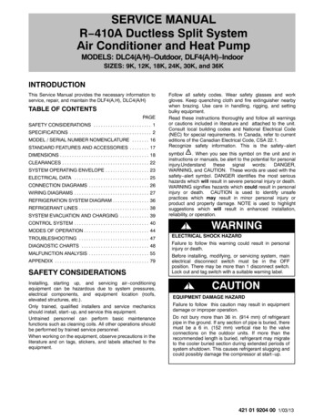
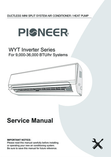
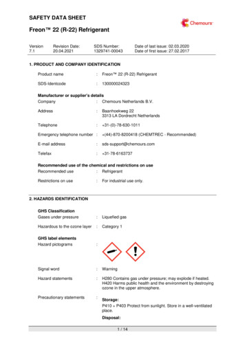
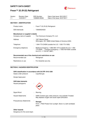
Split System Refrigerant Piping GuideR-410A Refrigerant1. Determine Equipment LocationThe location of the split system major components hasan effect on piping sizes and the accessories that areneeded for a properly operating system. There are fourcomponent configurations that are possible and they areshown in the following Layouts I through IV:Equipment location and vertical height between components will be used to determine the needed refrigerantline accessories in Table 6. Select the Layout that represents your application and record vertical height forthe project in the area provided.2. Actual Line LengthsFrom plans, estimates, and/or measurements, determine the actual line lengths in feet between the locationof the evaporator and the condenser sections. Recordthese values for each line size on Table V, Line 1, Equiv-alent Length and Pipe Size Summary on page 6. Page 9provides a convenient location for sketching the layoutof the project.3. Preliminary Pipe Size SelectionPipe sizes are based on the amount of refrigerant flowingthrough them and, for that reason, preliminary pipe sizeselections can be made based on the nominal size of theunit’s compressor (or in multiple compressor units basedon the nominal compressor tonnage of each circuit).falls between the 25 ft. increments on the chart selectthe smaller size for the preliminary selection. Record thisOD size selected on Line 3 of Table V. Once the equivalentlengths of fittings has been determined, this same tablewill be reviewed for final size selections.Using the actual line lengths recorded in Step 1, add 50%to this value and record this in Table V, Line 2, for eachline.Repeat the process for both the suction & liquid lineusing Table II and Table III and the actual pipe lengths 50% between the condenser and evaporator sections.When completed, record the selected line size OD’s foreach line in Table V, Line 3 If hot gas bypass is being installed, select this line size in the same manner-usingTable II and 50% of the circuit tonnage to make the selection.Using the nominal compressor tons per circuit, select thedischarge line size (Not required for a condensing unit)based on the actual line length 50% between the compressor and condenser sections using the EquivalentLengths shown in Table I. When the actual line lengthResealable Refrigerant FittingsMost models feature Resealable Refrigerant Fittings. Unit sections can beshipped split or split in the field without losing the factory charge resultingin no field brazing and a total installed cost advantage.Subject to change without notice.305.60-TD (0117)
Split System Refrigerant Piping GuideR-410A RefrigerantLayout ILayout eetEvaporatorLiquid Net DownMax HT 100'Liquid Net DownMax HT 20'Layout IIILayout CondenserFeetLiquid Net DownMax HT 50'Liquid Net DownMax HT 50'Note: If actual weights exceed the maximum shown, contact the factory.Table ect to change without notice.Discharge LineMaximum Equivalent line length in 05.60-TD (0117)
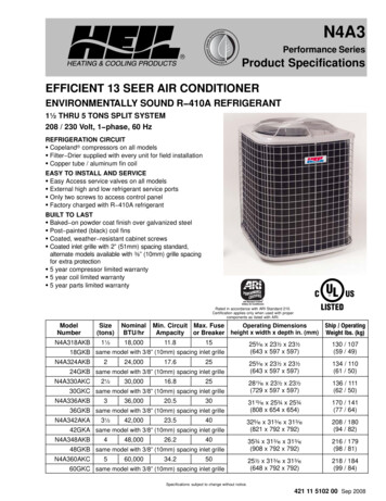
Split System Refrigerant Piping GuideR-410A RefrigerantTable tion LineMaximum Equivalent line length in ⅝1⅝2⅛Table bject to change without notice.Liquid LineMaximum Equivalent line length in ⅝¾¾⅞⅞1⅛505.60-TD (0117)
Split System Refrigerant Piping GuideR-410A Refrigerant4. Equivalent Length of ElbowsTable IV - Equivalent Length of Elbows*The next step is to account for the pressure drop attributable to fittings in each refrigerant line. For simplification, counting 90 elbows is sufficient for estimating linesizes.For each refrigerant line, and from plans or schematics,count the number of elbows in each refrigerant line andrecord the number on Line 4 of Table V.Using the preliminary line sizes selected in Step 3, goto Table IV, Equivalent Length of Elbows, and record theequivalent feet for each elbow size on Line 5 of Table V.Then multiply the number of elbows times the equivalentline length of each elbow as shown on Line 6 of Table V.Line OD (inches)Equivalent 5/83.8* Based on long radius elbows.5. Total Equivalent Line LengthUsing Table V, add the equivalent length of elbows (Line6) to the actual line lengths (Line 1) to arrive at the TotalEquivalent Line Length for each refrigerant line as shownon Line 7.Equivalent Line Length shown in the table. If it is not,select the next larger line size and record this on Line 3of Table V as your Final selection.Since the calculated Total Equivalent Line Lengths maybe significantly smaller than the actual line length 50%used in the preliminary selection, you may be able toreduce the line size from the preliminary selection. Inthis case, use the table to select the smallest diameterline that falls just below the maximum equivalent lengthshown in the tables. Record this on Line 3 of Table V asyour final selections for each line.The last step in the process is to verify that the sizes ofrefrigerant lines selected in Step 3 are valid for the calculated Total Equivalent Lengths of each line.Using the Nominal Compressor Tons and the line sizesselected, refer to Tables I - III and verify that the TotalEquivalent Line Length is below the Maximum TotalTable V - Equivalent Length and Pipe Size SummaryDischarge Line1. Actual Line Length2. Actual Line Length 50% (1 x 1.5)3. Preliminary Line Size OD”(from Tables I through IV)FinalSuction LineFinalLiquid LineFinalExt. HGBP LineFinal4. Number of Elbows in Refrigerant Line5. Equivalent Length per Elbows(Table VI)6. Equivalent Length for ALL Elbows(lines 3 x 4)7. Total Equivalent Length (Lines 1 6)**Note: If any equivalent length exceeds 150 Ft. contact factory.Subject to change without notice.605.60-TD (0117)
Split System Refrigerant Piping GuideR-410A Refrigerant6. Refrigerant Line Accessory RequirementsDepending on the location of the equipment within the building, there may bea need for optional components for the protection of the compressors and forefficient flow of refrigerant and oil throughout the system. Most of these accessories are factory mounted and all should be ordered with the equipment oncetheir need is determined.The most common refrigerant circuit accessories include:Resealable Refrigerant FittingsMajor components of the unit are fitted with resealablerefrigerant fittings as standard. When sections are split,loose resealable fittings or interconnecting kits are availableto facilitate installation. Kits include both the needed fittings as well as schraeder connections to simplify chargingof the refrigerant lines after connections are made.Oil SeparatorInstalled in the discharge line of the compressorto capture most of the oil leaving the compressorand to return it back to the compressor. At thesame time, it allows a small amount of oil to continue to circulate through the system to providethe needed lubrication to other devices throughout the system.AccumulatorInstalled in the suction line near the compressor and provides a liquidreservoir to capture any liquid returning in the suction line in orderto protect the compressor from damage due to liquid “slugging”.Quench ValveIs located near the compressor and is used to lower the suction gastemperature by injecting liquid refrigerant into the suction line to protect the compressor from damage due to excessive heat. It is generally required when hot gas bypass or long suction lines arepresent. When used, an accumulator must also be included.Liquid Line Solenoid ValveInstalled in the refrigerant liquid line to shut off flow in order toallow the compressor to pump liquid refrigerant out of the evaporator (pumpdown) and store it in the condenser prior to shutdown. This protects the compressor from “slugging” on start-up.The simplest way to determine the need for any of these accessories is torefer to Table VI, Accessory “Tests”. Using the vertical height between sections from Layouts I - IV, and the equivalent lengths of each line from Table V,conduct the six tests shown in Table VI. As you do so, make note of the accessory items required and be sure to include them in your project quotation.Subject to change without notice.705.60-TD (0117)
Split System Refrigerant Piping GuideR-410A Refrigerant 10050501005050XXXXXLiquid LineSolenoid ValveQuench ValveDischarge line greater thanExternal Hot Gas Bypass line greater thanLiquid line net down and greater thanSuction line greater thanSuction line in ambient greater than 100ºF and greater thanSuction line net down and greater thanAccumulator1.2.3.4.5.6.Requirements (a) (b)Oil SeparatorEquivalent FeetTable - VI Accessory “Tests”XXXX(a) Additional information on accessories can be found in price books and at www.unitedcoolair.com(b) Some accessories are included with other options available on units. Refer to the applicable price book.Subject to change without notice.805.60-TD (0117)
Split System Refrigerant Piping GuideR-410A RefrigerantSubject to change without notice.905.60-TD (0117)
Unique Solutions for All-Indoor HVAC ProjectsVertiCool ClassicVertical, 3 - 30 TonVertiCool AuroraVertical, 3 - 35 TonsPortable Cooling andHeating Units3-30 TonsC13-Series Horizontal2 - 10 TonsVariCool VAV, 9 - 70 TonsVariCool EZ-FitVAV, 12 - 90 TonsC-Series Horizontal1 - 15 TonsOmegaAir Vertical100% Outside Air, 1 - 15 TonsOmegaAir Horizontal,100% Outside Air, 1 - 15 TonsSpecial ConfigurationEngineered to OrderLIMITED WARRANTYAuthorized Distributor:United CoolAir Units are backed by a 1 year limited warranty onparts and a 5 year limited warranty on the compressor (labornot included). Maintenance items such as filters and belts areexcluded under this limited warranty.FACTORY TESTEDAll units are functionally run tested before shipment to ensurea trouble-free start-up and unit commissioning. Industry provencomponents are used throughout to enhance system reliabilityand peace of mind.Scan to learn moreabout all of ourproducts!491 East Princess Street, York, PA 17403 Phone: 717-843-4311 Fax: 717-854-4462email: uca@unitedcoolair.com web: www.unitedcoolair.comCopyright by United CoolAir Corporation 2015. All rights reserved.
through them and, for that reason, preliminary pipe size selections can be made based on the nominal size of the unit’s compressor (or in multiple compressor units based on the nominal compressor tonnage of each circuit). Using the actual line lengths recorded in Step 1, add 50% to this value and record this in Table V, Line 2, for each line. Using the nominal compressor tons per circuit .