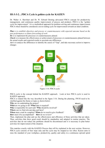
Transcription
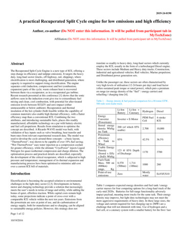
2019-24-0190A practical Recuperated Split Cycle engine for low emissions and high efficiencyAuthor, co-author (Do NOT enter this information. It will be pulled from participant tab inMyTechZone)Affiliation (Do NOT enter this information. It will be pulled from participant tab in MyTechZone)AbstractThe Recuperated Split Cycle Engine is a new type of ICE, offering astep change in efficiency and tailpipe emissions. It targets the heavyduty, long-haul sector (trucks, off-highway, rail, shipping), whereelectrification is most challenging, and distributed generation, wherecapacity is required to support rising electrification. The engineseparates cold (induction, compression) and hot (combustion,expansion) parts of the cycle; waste exhaust heat is recoveredbetween them via a recuperator, as in a recuperated gas turbine.Recent research presented at this conference [1] shows that the sonicairflows seen in the induction event give rise to extraordinary fuelmixing and clean, cool combustion, with potential for after-treatedemission levels between SULEV and zero-impact (eitherunmeasurable or below ambient). Recuperation and thermalinsulation of the hot cylinder (both feasible within the capability ofcommon materials) also enable high thermal efficiency, with a flatterefficiency map than a conventional ICE. Combining the twoattributes, and introducing sustainable fuels, places this readilymanufactured, affordable technology on a par with battery-electricand fuel cell propulsion. Results from simulation to optimise theconcept are described. A Ricardo WAVE model was built, withvalidation of key inputs such as valve breathing, heat transfer andburn-rates from relevant experimental research data. The model wasused to develop the cycle around three concepts – a basic layout,“ThermoPower”, was shown to be capable of over 10% fuel saving;“Wet ThermoPower” uses water injection as a compression coolantfor greater efficiency, while the ultimate “CryoPower” injects LiquidNitrogen for quasi-isothermal compression and charge dilution. Theoptimisation process and practical details are described, especiallythe development of the critical recuperator, which is subjected to highpressure and temperature; management of its thermal expansion andmanufacturing process have been optimised to minimise add-costover a current ICE bill of materials.IntroductionElectrification is becoming the accepted solution to environmentalchallenges in the light duty sector [2,3]. Developments in battery,motor and charging technology provide a solution that increasinglymeets the user’s needs in terms of range and utility, while adding thebonus of quiet, effortless traction. While capital costs remain hightoday, some projections indicate a point of cross-over with acomparable ICE vehicle within the next ten years. Emissions fromthe powertrain are zero at point of use, and de-carbonisation ofenergy supply, both for manufacture and re-charging, can be alignedto sustainable energy policies. However, this strategy does notPage 1 of 1210/19/2016translate so readily to heavy duty, long-haul sectors which currentlyemploy the ICE, usually in the form of a turbocharged Diesel engine.These sectors include Medium and Heavy duty trucks; Construction,industrial and agricultural vehicles; Rail vehicles; Marine propulsion;and Distributed power generation sets.Unlike the passenger car, these sectors are often characterised byvery high levels of utilisation (12-24 hours per day) and load factor(often sustained peak torque or rated power), which puts a premiumon range (or energy density of the “fuel” / energy carrier) andrefuelling / charging time [4].Table 1: – Energy density & fuel payload comparison for a 40-tonne GTW,500-mile semi-trailer ed energydensity Wh/kginc TankPowertrainefficiency% Tank toWheelUsable EnergyDensity(Stored x Effyx DoD) Wh/kgFuel TankMass, 500 mi(800km)range,KgPoint-of-useemissionsLi-Ion CatenaryHydrogenDieselInverter E-MotorPEM FuelCell4-strokeICE200 (of which 85%usable)2,70010,00085%42.5%36.5%123 @ 85% Depthof I/US10Zero1,714(100mi)Table 1 compares expected energy densities and fuel tank / energycarrier masses for four competing options for a long-haul truck of theearly-mid 2020s. Batteries for full-range functionality adverselyimpact payload, meaning more trucks for the same task. Their energydensity may improve, but light duty technologies may not meet themore aggressive requirements of heavy duty. In these large sizes, thevoltage and current required for fast charging (up to 2MW) are achallenge that will not diminish with time. Use of hydrogen and afuel cell, or a catenary system with a smaller battery for the first / last
100 miles, reduces these challenges, but both require unprecedentedinfrastructure investment to be useable.This situation poses a simple question: What if the ICE couldperform well enough to compete with these zero-emissionalternatives, both for local air quality and efficient use of sustainableenergy? In practical terms, this necessitates very low engine-outemissions, so that an after-treated system can approach the point ofzero impact; and high thermal efficiency, so that carbon emissionscan be reduced and future, more costly sustainable fuels can be usedsparingly. This paper, together with that of Morgan et al [1], presentsthe development of recuperated split-cycle engines that meet thoseneeds.The Recuperated Split Cycle EngineSplit Cycle EnginesThe split cycle separates induction/compression andcombustion/expansion phases of the four-stroke cycle into a pair oftwo-stroke cylinders, allowing each to be optimised for its purpose.The principle is by no means new. The Backus Water MotorCompany produced engines with separated compression andexpansion from 1891 [5], while a form of split-cycle was embodiedin Ricardo’s Dolphin engine in 1905 [6], renowned at the time forclean and efficient operation. More recently the principle has beenexplored by Scuderi [7,8], Caterpillar [9], Coney [10] and others [11],although most have not included recuperation in their cycles, to thedetriment of efficiency potential.Recuperationmanner as a 4-stroke cycle, but at TDC the air is discharged – thecompression cycle is very similar to an industrial compressor, exceptthat a higher pressure ratio, circa 20:1, is required. The discharged airis passed through a recuperator, where hot exhaust gases add heat.Again, this principle is well known in the recuperated gas turbine.The air is now a hot, supercritical fluid – up to 70 bar and 700 C. It is“injected” into the expander cylinder at around TDC, where it meetsinjected fuel, giving rise to a very energetic mixing event. It is thismixing, plus the controllability of intake conditions at the point ofignition, which are believed to be responsible for a cool,homogeneous combustion phenomenon (similar to HCCI, but muchmore controllable and stable), and very low levels of engine-out sootand NOx [1,12,13]. Research has already demonstrated that SULEVNOx levels are possible; with development, tailpipe NOx can bereduced below observed city ambient levels.Efficiency improving featuresTwo measures extract maximum efficiency from the expansion event.First, the expander cylinder can be of different size to thecompressor, enabling a Miller-cycle principle to be employed. Pastresearch has shown that a displacement of up to three times that ofthe compressor can be beneficial [8,10]. Second, the expander can beinsulated. Thermal insulation was extensively researched on 4-strokediesel engines in the 1980s, with limited success [14]. The issue wasthat benefits to the combustion and expansion processes were negatedboth by a lack of added expansion capacity, and by a detrimentalimpact of hot walls on the colder intake and compression events.With an enlarged, dedicated hot cylinder, these issues do not apply;insulation is able to convert combustion heat into either useful work,or hot exhaust whose enthalpy is recycled via the recuperator.Isothermal and cooled compressionThe first recuperated split-cycle piston engine of recent times was theIsoengine proposed by Coney [10], with two levels of prototypeeventually being built and tested [15,16]. This engine added a finalfactor to the thermodynamic cycle, that of quasi-isothermalcompression. If the compression cylinder is kept cool during thecompression process, a lower level of compressor work is required(similar to the effect of multiple stages of intercooling), while therecuperator provides sufficient heat to return the compressed gas tothe desired hot state for combustion. The Isoengine employed nonevaporating water as a compression coolant, achieving compressordischarge temperatures of below 90 C, compared to an adiabaticdischarge of over 260 C [16]. This equated to a 17% reduction incompressor work, and as this will be around 30% of gross expanderoutput, an overall increase in thermal efficiency of more than 5%results from this effect alone. The authors reported potential for fuelto-electricity efficiency of 57% to 60% for a 3MW unit, although thiswas not fully demonstrated in hardware.Figure 1: Recuperated Split CycleFigure 1 shows the basic principles of the recuperated split cycle. A“cold” compressor cylinder inducts air (from a conventional aftercooled turbocharging system), then compresses it in much the samePage 2 of 1210/19/2016Non-Evaporating water is a convenient, non-toxic cooling fluid withgood specific heat capacity. However, the quantity required isrelatively large, as sensible heating provides just 125kJ/kg of cooling[17]. In addition, the post-compression separator and water coolingsystem are relatively large for transport use; the practicalities ofejecting liquid-phase water as a mixture with compressed gas througha discharge valve tend to limit this type of device to low operatingspeeds. A greater cooling effect can be obtained by using the latentheat of vapourisation of the water (2257kJ/kg), meaning lowerquantities injected, a finer spray with better heat transfer, and no
liquid to eject at the top of compression. However, this approach islimited by the pressure and temperature conditions duringcompression, relative to how water’s boiling point varies withpressure. Figure 2 shows the evolution of temperature in a typicalpolytropic compression of a split-cycle engine, compared to theboiling point of water at the same pressure. The ability to cool byvapourisation only arises after 60 BTDC (11.5 bar pressure). In theIsoengine compressor test cited above, the discharge pressure was 13bar; here, water boils at 190 C, compared to an adiabatic discharge of260 C and an observed convection-cooled temperature of below90 C [16], so a vapourising-water approach would achieve less thanhalf of the effect observed.tool that embraces models of gas dynamics, component maps, fuelinjection, combustion and heat transfer [19]. Early studies [17] hadindicated potential for an indicated thermal efficiency of at least 60%with effective recuperation and compression cooling, and 70% withinsulation of the expansion process added. The challenge now was todevelop a more detailed and realistic model, with validation of eachdesign input against criteria suitable for building a real engine.Figure 3: Concept Development and Modelling MethodologyFigure 2: Polytropic compression and water boiling temperatures.There is certainly great value to the vapourised-water approach, as itrepresents both a cost-effective half-way house to full quasiisothermal compression, and a potential means of managingexcessive combustion temperatures in the expander. However, toobtain the most efficient, near-isothermal compression in a transportor mobile engine, a further approach is required. Liquid Nitrogen(LiN) offers a solution, being a readily available industrial fluid witha very low boiling point compared to compression conditions. LiNhas a lower latent heat of vapourisation than water (199 kJ/kg vs2257 kJ/kg at standard conditions), but this value is substantiallyincreased by sensible heat, to around 475kJ/kg [17].This study has therefore looked at the efficiency potential of threevariants of the recuperated split-cycle engine [18]: “DryThermoPower” is a basic unit without any form of compressioncooling apart from the intercooler after the turbo-compressor; “WetThermoPower” adds injection of water into the compressor, up to thelimit of what will vapourise; and finally “CryoPower” uses LiN as acompression cooling medium.Figure 3 shows the approach taken. Modelling has focused on threekeypoints in the engine’s speed-load map:1.2.3.A30 (1100 rpm, 30% load) represents highway cruiseA80 (1100 rpm, 80% load) is the “efficiency eye” of atypical 4-stroke engine, and represents uphill cruiseB100 (1600 rpm, 100% load) is the engine’s rated power.To minimise model run-time, initial optimisation was performedusing a cylinder pair, representing the power output of one-third of atypical 13 litre, 375kW truck engine. In this approach, the sizes ofcompressor and expander cylinders are very different, which isinconvenient for conventional engine construction but permitted apragmatic first step to a multi-cylinder model with unequal numbersof each cylinder type.Concept Modelling MethodologyWAVE modelsA single cylinder research engine, representing the expander half ofthe cycle, has been used to demonstrate the potential of thetechnology for low emissions, especially NOx [1,12,13]. However,this approach is of limited use for optimising the wider system, as thecompressor hardware is absent, and losses to friction and heat are notrepresentative of a better integrated multi-cylinder unit. To optimise aconcept for a first fully integrated multi-cylinder prototype, a modelwas built using Ricardo WAVE, a one-dimensional virtual-enginePage 3 of 1210/19/2016Figure 4: Illustrative split WAVE cylinder-pair modelThe standard features of the WAVE
The Recuperated Split Cycle Engine is a new type of ICE, offering a step change in efficiency and tailpipe emissions. It targets the heavy duty, long-haul sector (trucks, off-highway, rail, shipping), where electrification is most challenging, and distributed generation, where capacity is required to support rising electrification. The engine
