Transcription
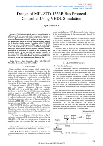
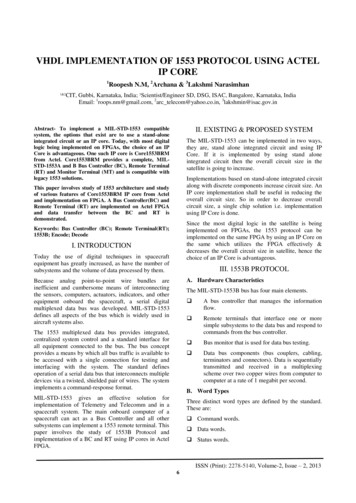
International Journal of Advancements in Research & Technology, Volume 5, Issue 5, May-2016ISSN 2278-77631MIL-STD-1553 BUS PROTOCOL ALGORITHMSIMPLEMENTATION ON FPGA TO REALISESYSTEM - ON-CHIP(S O C)K. Padmanabham1, Prabhakar Kanugo2, M. Chandrashekar3, K. Nagabhushan Raju41,Analogic Controls India Ltd – Hyderabad-.1, E-mail: padmanabham@analogiccontrols.com2,Analogic Controls India Ltd – Hyderabad, . 2E-mail:kpkar@analogiccontrols.com3Bharat Dynamics Limited, Hyderabad, India, 3E-mail: cmatham@gmail.cpm4Dept of Electronics, SK Univ., Ananthpur, India, 4E-mail:knrbhushan@yahoo.com,Absrtact : This paper provides design approach to device “System-On-Chip (SoC)” usingFPGA with MIL-STD-1553B protocols and controller. This is possible by using FPGA havingMIL-STD-1553 protocols and microcontroller/processor IP cores within the SoC. The majoradvantage in having SoC is that the application firmware can be embedded within the SoC forfurther increase of processing power. The major advantages are cost reduction, physical size/foot print reduction, increase in the processing power to handle complex algorithms andavailability at a shorter notice.Keywords: System-On-Chip(SoC), FPGA, MIL-STD-1553B, Protocols, Micro Controller, IPCore and AlgorithmsIJOART1 IntroductionMIL-STD-1553 network/bus is a heterogeneous architecture where the various On-BoardComputers (OBC ) and terminals have a master/slave relationship. Message communication iscontrolled by one master terminal called the Bus Controller (BC) the other slaves called RemoteTerminals (RTs). The BC initiates all communications between the slaves.MIL-STD-1553 is a military standard that defines the electrical and functional characteristics ofa serial data bus. It is designed as an avionic data bus for use with military avionics sub-systemscommonly used in spacecraft on-board data handling subsystems, both military and civil. Thisbus can handle up to 30 Remote Terminals (devices)[8].The MIL-1553-STD will stay for another 30 years to cater military, aircraft, other vehicles,Space etc. At this juncture the bus provides enough horsepower to handle routine aircraftcommunications with ease. Also the communication to happen in a deterministic, fault tolerantand keeping the redundant feature of the Mil Bus.22.1System-on-Chip Implementation schemeBlock diagram with descriptionThe design is focused on generation of MIL 1553 Bus protocol algorithms suitable to implementin a FPGA using VHDL code to realize System-On-Chip (SoC) device. The SoC also requirescontroller core for interfacing with HOST and connect to MIL 1553 bus.Copyright 2016 SciResPub.IJOART
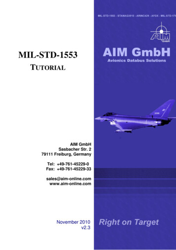
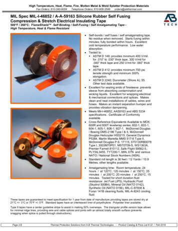
International Journal of Advancements in Research & Technology, Volume 5, Issue 5, May-2016ISSN 2278-77632Fig(1) : System-on-Chip Implementation scheme Block diagramThe methodology adapted to realize System On Chip (SoC) with Protocol controller using ARMIP-Core and implementing MIL-STD-1553 bus protocol algorithms, both in a single Chip FPGAas shown in Fig(1).2.2Major Functional Blocks in the Implementation.The protocols are divided into the following major functional blocks for easy implementation, asshown in Fig(2).IJOARTTable (1) Major Functional Blocks1. Protocol Controller based on ARM IPCore.2. Memory3. BC/RT/MT Protocol IP Corel.4. Transmit(Tx) Data FIFO for commandwords.7. Receive (Rx) and Shift registers.8. Manchester encoder9. Manchester decoder.10. Transmitting Logic.11. Receiving Logic.5. Receive (Rx) Data FIFO for status words.6. Transmit (Tx) and Shift Registers.Copyright 2016 SciResPub.12. 1553 Isolation Transformer (Tx)IJOART
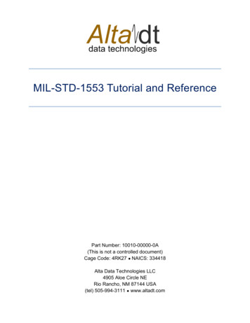
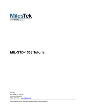
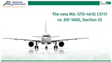
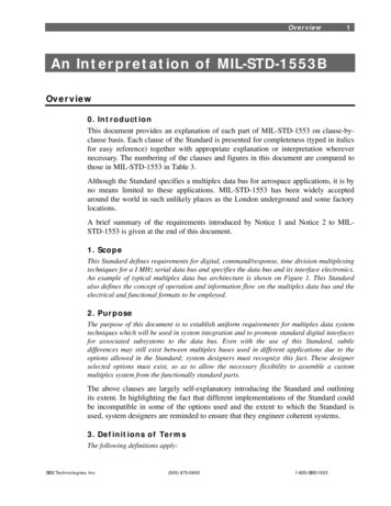
International Journal of Advancements in Research & Technology, Volume 5, Issue 5, May-2016ISSN 2278-77633Fig(2) MIL-1553 System Architecture for System on Chip (SoC) design.2.2.1 Protocol Controller:IJOARTThe protocol controller is basically IP Core installed in the SoC to perform the supervisory roleof interconnecting all the functional modules of the SoC with Host and MIL bus. Proposed touse the “ARM IP Core” for this supervisory function. The protocol controller will have Twointerfaces i.e Serial Port and JTAG. The “Serial port” is meant for connecting to the Host for theData to transmitting or to Receiving from the 1553 MIL Bus. The JTAG port is forprogramming the code into the SoC.2.2.2 Memory:The memory part of SoC, acts like buffer and to store the incoming and outgoing data under thesupervision of protocol controller.2.2.3 BC/RT/MT Protocol IP Core :The main functions to be implemented in the IP Core, are the communication between BC,RTs.The communication between BC, RT is nothing but the 1553Bus protocols, these protocols areset of messages exchanged between the BC & RTs.The BC operates as a bus controller. The BC initiates all information transfers on the data bus.The BC sends commands to the RTs for execution. The RT is the device that connects the databus to the sub-system and transfers data in and out of the subsystem in response to the BCcommands. The MT function is to examine the activities on the bus and record all data orselected data for off-line analysis and use for backup.As a case study, Algorithms generated for commands from BC to RT as shown in Fig(3) andRT to BC as shown in Fig(4) i.e RT response to BC, are given below, can be implemented inFPGA.Copyright 2016 SciResPub.IJOART
International Journal of Advancements in Research & Technology, Volume 5, Issue 5, May-2016ISSN 2278-77634IJOARTFig(3) BC to RT command word passing FlowchartCopyright 2016 SciResPub.IJOART
International Journal of Advancements in Research & Technology, Volume 5, Issue 5, May-2016ISSN 2278-77635IJOARTFig(4) RT to BC Data TransferCopyright 2016 SciResPub.IJOART
International Journal of Advancements in Research & Technology, Volume 5, Issue 5, May-2016ISSN 2278-776362.2.4 Command word in 20 Bit patternThe above Algorithms will generate a 20 Bit word in the pattern given in the Fig(5).These 20 bitmessages to be converted into serial form and encode into machester encoding to make suitablefor transmitting onto 1553 bus. These word messages are stored in Transmit & Receive DataFIFO’s the series of commands from the protocol controller are loaded onto 16 bit bidirectionaldata bus and written in “Tx Data FIFO” 16 bit registers. The commands from the FIFO registerare converted from parallel to serial by Tx register and shift registers. The serial command isencoded into Manchester coding and transmitted onto the bus by transmitting logic. Similarlythe Status/data words from the bus are received by the receiver logic, decoded by Manchesterdecoding and converted into parallel by Shift & Receiver registers then written into the “RxData FIFO” 16 bit register.IJOARTFig(5) 20 Bit 1553 Bus Command, Data and Status word formatsThe output messages from the registers are converted into Manchester encoding/decodingManchester II Encoding & Decoding : The critical functional block in MIL-STD-1553 bus isManchester encoding & decoding . The Mil Bus is defined to be bipolar, and encoded in aManchester format, so no DC component appears on the bus. This allows transformer couplingand excellent isolation among systems and their environment.3The Manchester CodeThe Manchester code is a line code in which the encoding of each data bit has at least onetransition and occupies the same time and has no DC component. The DC component of theencoded signal is not dependent on the data and therefore carries no information, allowing thesignal to be conveyed conveniently by media which usually do not convey a DC component.Signal is inductively coupled to the bus and the clock signal can be recovered from the encodeddata.Manchester code always has a transition at the middle of each bit period. The direction of themid-bit transition indicates the data. They exist only to place the signal in the correct state toallow the mid-bit transition. The existence of guaranteed transitions allows the signal to be self-Copyright 2016 SciResPub.IJOART
International Journal of Advancements in Research & Technology, Volume 5, Issue 5, May-2016ISSN 2278-77637clocking, and also allows the receiver to align correctly, the receiver can identify if it ismisaligned by half a bit period.3.1The Encoder blockThe Encoder block converts the incoming 16bit serial data from the Tx Data FIFO into Serialoutput adding 3 bits Sync and parity bits and makes the 20 bit word. This block is divided intotwo sections, parallel to serial conversion and parity bit adding with Manchester coding.3.2The DecoderThe Decoder is continuously monitors its data input lines for a valid sync character and twovalid Manchester data bits to start the cycle. When a valid sync is recognized , the type of syncis indicated on COMMAND/DATA SYNC outputIf the sync character is a command sync, next sixteen clock periods data will be sent to Shiftregister to convert serial into parallel date. After all sixteen decoded bits have been transmittedthe data is checked for odd parity and shifted into an Rx Receive register on every low-to hightransition of clock.A typical Manchester encoding scheme is depicted below:-IJOARTFig(6) Manchester coding.4(Courtesy : www.interfacebus.com)Conclusions:The Various blocks have been simulated using Xilinx Vivado development environment.Language used is VHDL which is portable across any target FPGA device. Functionality wasverified through timing simulation. Physical realization of the product can be planned with anyavailable FPGA with a gate count 700K or more.MIL-STD-1553 is a command/response, time-multiplexed, serial data bus with a 1 Mbit/sec datarate. The bus contains a bus controller and up to 31 remote terminals. Our cores meet allrequirements for dual-redundant bus operation for use with its devices in high reliabilityapplications.Copyright 2016 SciResPub.IJOART
International Journal of Advancements in Research & Technology, Volume 5, Issue 5, May-2016ISSN 2278-77638References:[1]Theresa George, J. Mangaiyarkarasi. Electronics and Communication, Anna University,India. “Design and Implementation of Mil-Std-1553B Bus Protocol Controller withFPGA and ASIC Sharon”, IJREAT, June-July-2015, Volume 3, Issue 3, ISSN: 2320 –8791.[2]“Hardware-Software Co-design for SoC” Part of the SoC Design Flow and ToolsCourse, Department of Computer Science & Information Engineering, National ChungCheng University Chiayi, Taiwan.[3]Amrutha V., Anu James, Sreejesh K. V. “MIL-STD-1553B Bus ControllerImplementation: A Review” 7th June 2015, Proceedings of 26th IRF InternationalConference, Chennai, India, ISBN: 978-93-85465-30-7.[4]Enumala Srikrishna, Asst.professor, Thandra Paparaya Institute of Science andTechnology, Bobbili, India, L.MadanMohan Sr.Engineer, Adept Chips, A.MallikarjunaPrasad, Associate Professor, JNTUK, Kakinada “Development of MIL-STD-1553BSynthesizable IP Core for Avionic Applications”, IJCSI, September 2011, Vol. 8, Issue5, No 3, ISSN (Online): 1694-0814.[5]Sandi Hubric, “Using VHDL Cores in System-On-Chips Development”, EuropeanSpace Agency – Netherlands.[6]Fabrizio Ferrandi, Giovanna Ferrara, Roberto Palazzo, Vincenzo Rana, Marco D.Santambrogio, “VHDL to FPGA automatic IPCore generation: A case study on Xilinxdesign flow”, DEI - Politecnico di Milano.[7]Mr. Sameer Vaghela, “Mil-Std-1553B Interface & Test-Setup Design” E.C. Department,SardarVallbhbhai Institute of Technology, Vasad GTU- Gujarat, India.Prof. Y. B.Shukla, E.C. Department, SardarVallbhbhai Institute of Technology, Vasad GTUGujarat, India[8]MIL-STD-1553 Tutorial – Condor Engineering[9]MIL-STD-1553 DESIGNER’S GUIDE – Data Devices Corporation. 105 Wilbur PlaceBohemia, New York 11716-2482.[10]Jing Reng Huang, Madhu K Iyar, Kwang Ting Cheng University of California – CA“A self-test methodology for IP Core in Bus Based Programmable SoC”[11]Chandrashekar, et. al. “FPGA implementation of 1553 bus Interface Unit”, BharatDynamics Limited and et.al., E-mail: cmatham@gmail.cpm proc. of the Nationalconference on emerging trades in electronics & communication 2007, 23rd June ng a MIL-STD-1553 System Using Core1553 .http://www.microsemi.comCopyright 2016 SciResPub.IJOART
[8] MIL-STD-1553 Tutorial – Condor Engineering [9] MIL-STD-1553 DESIGNER’S GUIDE – Data Devices Corporation. 105 Wilbur Place Bohemia, New York 11716-2482. [10] Jing Reng Huang, Madhu K Iyar, Kwang Ting Cheng University of California CA – “A self-te