Transcription
MIL-STD-1553 Tutorial and ReferencePart Number: 10010-00000-0A(This is not a controlled document)Cage Code: 4RK27 NAICS: 334418Alta Data Technologies LLC4905 Aloe Circle NERio Rancho, NM 87144 USA(tel) 505-994-3111 www.altadt.com
CUSTOMER NOTES:Revision Control HistorySchedule Rev A Release Date: 6 Sept 2007Note to the Reader:This document is provided for information only. While Alta strives to provide the most accurate and up todate information, there are bound to be errors and omissions in this document. By using an Alta product(1) the customer or end user agrees to applicable Alta’s Standard Terms and Conditions of Sale,Standard Warranty and Software License and (2) shall not hold Alta Owners, Employees, Contractors orSales/Support Representatives liable for any loss of profit from said errors or product usage.Use of Alta products or documentation in violation of US export or ITAR laws voids all warranty and shallnot be supported.AltaCore, AltaCore-1553, AltaAPI, AltaView and AltaRTVal are Trademarks of Alta Data TechnologiesLLC, Rio Rancho, New Mexico USAContact:If there are any questions or comments, please contact us at 505-994-3111 or visit our web site forsupport submit forms at www.altadt.com or email us at info@altadt.com or support@altadt.com.
Table of Contents1553 Tutorial and Reference. 5Figure: 1553 Example Single Bus with Two Remote Terminals and One Monitor . 6A Brief History of Digital Data Busses and History of MIL-STD-1553. 61553 Basics. 71553A and 1553B Variants . 71553 Communication Basics. 71553 Layer One: Physical Layer . 8Wire, Couplers, Terminators and Bit Encoding . 8Figure: 1553B Bus Components . 9Terminology Review:. 9 Bus: . 9 Coupler:. 9Figure: Multi-Stub Coupler Example - Two Stub and Eight Stub Coupler . 10 Stub: . 10 Terminator: . 101553 Signal Encoding . 10Bus Problems and Troubleshooting . 111553 Troubleshooting Tips . 11Layer Two – Data Link Layer: Word and Message Protocols. 111553 Command Words. 121553 Hex Displays. 13Figure: 1553B Mode Code Table . 141553 Data Words. 141553 Status Word . 151553B Message Types and Structures . 15BC-RT Messages (Normal and Mode Code With and Without Data Word) . 17RT-BC Messages (Normal and Mode Code with Data Word) . 17RT-RT Messages (Normal and Broadcast) . 18BC Broadcast Messages (Normal and Mode Code) . 19
Integration Issues for BC, RT and Monitor Computers. 19Application Discussions. 20BC Review – Application Designs . 20Figure: Example BC Message and Framing Options . 21RT Review – Application Designs . 221553 Application Review – Polling or Interrupts . 22
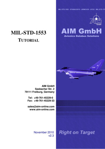
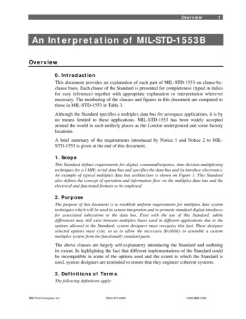
1553 Tutorial and ReferenceMIL-STD-1553 (1553) is a standard that describes a one megabit serial networkphysical layer (layer one: physical layer – PHY) and message level protocol (layer two:data link layer). Primarily used in legacy avionics, power, sensor and control systems,1553 has been deployed on thousands of applications worldwide throughout its 35 year existence including prototype passenger cars, oil platforms, subway controlsystems and the International Space Station. The US DoD gave-up oversight of thestandard (and most MIL-STD documents) in the early 1990s and the standard is nowoverseen by the Society of Automotive Engineers (SAE) as commercial document“AS15531.”This overview is designed to complement the referenced MIL-HDBK-1553A document,which provides an excellent detailed review of the 1553 standard (MIL-HDBK-1553ASection 20 provides a summary of MIL-STD-1553B Notice 2). Commercially availablechip-sets and interface cards (like Alta’s) “off load” the protocol processing (protocolengine) so the engineer’s primary concern is design/integration of application softwareand cabling issues. The following paragraphs will highlight the main points of thestandard that the design or system engineer needs to know for a successful integration.NOTE: When referencing the MIL-HDBK-1553A and MIL-STD-1553 documentspay particular close attention to “legal/illegal” and “required” message types andthe required support “bits” of an RT Status Word.) There are minimumimplementation requirements to be a compliant 1553B terminal and the designershould reference this information from the standard.NOTE: All the figures contained herein are provided in high resolution at the endof this document.The following diagram shows a crude example of a simple network with computers (BC,RTs and/or Monitor), bus cabling, transformer couplers, stub cables and busterminators. More description on these terms is provided in the following sections. Thecomputers shown in the picture could be actual Line Replacement Units (LRUs) or aPC/VME computer with an Alta 1553 interface card.
Figure: 1553 Example Single Bus with Two Remote Terminals and One Monitor(Not to Scale)A Brief History of Digital Data Busses and History of MIL-STD-1553Before diving deeper in the review, let’s have a brief history lesson Erwin Gangl wasone of the early pioneers in integrating digital computers into military aircraft whileworking as an electrical engineer at Dayton’s Wright-Patterson Air Force Base from1965 to 1988. In the late 1960s he was assigned to handle the digital computerrequirements in the F-15 program office. (Ref1)“With that came the requirement to set up the inter-communication with all of the otheravionic subsystems like the radar navigation controls and displays,” said Gangl, who’sconsidered by many to be the father of the data bus standard (Mil-Std-1553) that led toplug-and-play digital avionics. “Where in the past all signals were connected by stringingpoint-to-point wires, resulting in big cables and connectors, it became very frustrating tome that this couldn’t be done digitally. So I recommended that we go to a timeshareddigital multiplex data bus concept. The digital conversion is done at the sensor, and adigital signal is sent to the computer via a dual redundant shielded twisted wire pair.This replaced having to have the analog-to-digital converter hardware being part of thecomputer, and also reduced the number of wire cables needed to connect the computerto the rest of the avionics. It turned out that the concept was accepted, and wedeveloped the Mil-Std-1553 data bus standard that is still in use today.” (Ref1)Today, 1553 is regarded as a low speed computer interconnect standard that can bedeveloped with readily available, low-cost commercial components and is ideal forenvironmentally harsh environments (especially environments with electrical noise).(Ref1 IEEE-USA yrs.htm)
1553 BasicsA 1553 network (or bus in older terms) is a heterogeneous architecture where thevarious computers (terminals) on the network have a master/slave relationship.Message communication is controlled by one master terminal called the Bus Controller(BC). The BC initiates all communications between computer end points, which arecalled Remote Terminals (RTs). There can also be passive Monitor terminals that“sniff” or record bus traffic (message packets).The standard does not describe anything about application processes beyond the layertwo data link protocol, so it is completely up to the system designer to architect themessage frequencies and physical bus patterns. Since the 1553 topology consists ofone central BC computer initiating all communications, very deterministic messagetiming (to the tens of microseconds, but usually 100s of microseconds) can beachieved.1553A and 1553B VariantsThere have been two main variants of 1553, the “A” version (1553A) and the current “B”(1553B) version. The differences between the two are minor, but important and all newsystems (from about 1980) should be using 1553B. Some older aircraft (pre 1985) have1553A or mixed RT terminals so watch out for these systems. The Alta productssupport both 1553A and B. “Notice II” for 1553B was released in 1988 and is thecurrent document that most systems reference (including this discussion).1553 Communication BasicsA 1553 network is time division, half duplex communications where all transmissionsare on a single cable (unlike full-duplex Ethernet, RS-232/422 or ARINC-429 whereseparate transmit and receive wires are utilized). Only one computer terminal cantalk/transmit at any given time (time division) and the other computers listen/receive (fullduplex systems like Ethernet and RS-232 allow simultaneous transmit and receive ondifferent wires).For safety critical systems, there are one or more standby redundant busses (networks)that are strictly for back-up communications (data is not transmitted in parallel amongredundant busses). A common term for a 1553 network is “dual redundant bus,” whichmeans there are two independent busses (one bus is called the Primary or “A” bus andthe other is the Secondary or “B” bus).
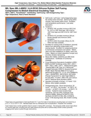
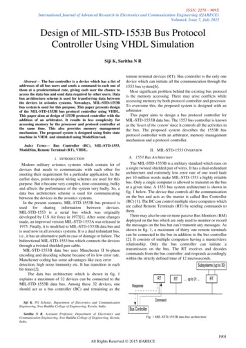
A simple 1553 network example may have one central computer (BC) and one or moresensor, power or motor control remote units (RTs). With more complex systems, theremay be several 1553 networks, each one with a single BC and several RTs (up to 31RTs) to control applications such as flight controls, sensor/power/motor controls, enginemanagement and/or stores management.The BC is usually the main system computer and often has common names such asflight control computer (FCC) or mission control computer (MCC), etc. In these multiplenetwork scenarios, a BC of one network might be an RT of another network (and thusprovide a bridge or gateway between the 1553 networks). In more modern systems, a1553 network may be a legacy connection to older computers (RTs) that are not in needof redesign (or can’t be due to cost, which it most often the case). Modern systems willoften have other networks (e.g. RS-485, ARINC-429, Ethernet, Fibrechannel orFirewire) for high rate data transfers between one or more computers.1553 Layer One: Physical LayerWire, Couplers, Terminators and Bit EncodingThe first thing to know about a 1553 network is how to physically build one bus. 99% of1553 problems (besides getting the software loaded!) are from incorrectly constructedbusses or broken bus components. A 1553 bus must be constructed as a 78 ohmbalanced topology and it is strongly recommended that transformer coupling be used(“direct coupling” uses T connectors and is only allowed on very old 1553A systems –Notice 2 of MIL-STD-1553 states that direct coupling should be avoided and states thatonly transformer coupling shall be used for US Army and Air Force systems – seesection 30.10.5). The following figure shows a properly constructed bus and itscomponents.
Figure: 1553B Bus ComponentsTerminology Review: Bus: The cable between couplers. Technically this can be any length, but therecommended length between couplers is 18 inches (this reduces reflections).The 1553B standard does not specify a maximum length because the generalthought was 1553B would go Fiber Optic by the mid 1980s. This was a mistakefor wired networks. The 1553A standard referenced a maximum length of 100meters and this should also be followed for 1553B systems. Coupler: Transformer interconnect from the bus to the stub of a BC, RT orMonitor. The transformer ratios are a step down from the stub to the bus with aratio of 1.41. (There is also a 1:1 transformer inside the BC, RT or Monitorcomputer to isolate internal shorts to the bus). The standard also allows for“direct” or T connector coupling, which was used on older F-18 systems, butdirect coupling is NOT recommended (and shall not be used on US Army and AirForce systems – See Notice 2 section 30.10.5).o There are multi-stub couplers, which simply mean there are multiple singlestub connections in the same box. Don’t get confused and use a multistub coupler to connect the one computer to both the primary (A) orsecondary (B) redundant bus. Multi-stub couplers allow multiplecomputers to be connected to the SAME bus.
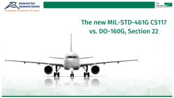
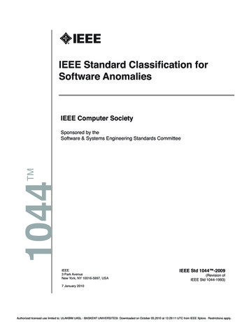
Figure: Multi-Stub Coupler Example - Two Stub and Eight Stub Coupler Stub: The cable between the transformer and the BC, RT or Monitor. Themaximum length of the stub cable is 20ft for a transformer-coupled bus.Recommended lengths are 18 inches to 18 ft. Remember that the total stublength includes backplane and PCB trace lengths to the required isolationtransfer inside the BC, RT or Monitor (see the standard for more details – most1553 chip manufactures provide the proper reference drawings for the circuitcard design). Many people try to have stub lengths longer than 20ft and thisusually causes problems. Try not to exceed 18ft (this gives a bit of leeway inyour design). If you do use direct coupling, your stubs must not exceed 1 foot(12 inches). Terminator: 78 Ohm End Cap at the end of the bus cable or last coupler onBOTH sides of the bus. Do NOT put terminators on stub connections – this putsa significant load on the bus.1553 Signal Encoding1553 uses Manchester II Bi-Phase (Return to Zero) encoding for bits. The followingfigure shows this format for a bit time. When the bus is idle (no transmission), the bussignal should be at ground. Please see the MIL-HDBK-1553A document for details onbus signaling, levels and testing/measurements. The bit rate for 1553 is one mega bit,but the bi-phase encoding means the frequency is 2 MHz. For most 1553 transceivers,the signals are encoded with bi-level signaling from the digital circuit to the PHYtransceiver (the various chip manufacturers document this very well).
Bus Problems and TroubleshootingOne common integration problem is where the user tries to cheat and hook-up a BC toan RT with just a single cable. This will not work. A complete bus with stubs, couplersand terminators is required. The simplest bus for two computers is two stub cables, onedual stub coupler with terminators on both sides (and no bus cable). Manufacturersmake 1-8 stub couplers (and probably more) – these are great for lab and testscenarios.Today’s ASICs and FPGA protocol engines (like Alta’s) that encode/decode 1553signals are rock solid and rarely fail unless there is excessive loading (impropertermination or cabling) or you just got a bad part. 1553 transceivers should be able tohandle transmit to ground or high loading, so most issues are usually in the cable plant.The transformer coupling that protects the bus from DC shorts also prevents commonequipment like Time Domain Reflectometers (TDR) from being used to help isolate busproblems/shorts. The best method for troubleshooting a cable length is to have a highimpedance load (this is beyond the scope of this discussion). Just remember that ifyou’re having intermittent problems, first check all cabling, couplers and terminators.1553 Troubleshooting Tips¾ Start with the terminators: Terminators are usually the easiest to get accessto and simple to swap-out¾ Then try shortening the bus in segments to isolate cable runsIn general, you do not need to know or care about 1553 bits and signals are encoded:the chip-set or interface card implement the physical layer for the computer. The MILHDBK-1553A document provides good detail on the electrical requirements of the PHYlayer.Layer Two – Data Link Layer: Word and Message ProtocolsFor many 1553 implementations, the designer does not need to know the data linklayer: the designer’s application programs (or process) will simply make a function callto make a data packet transfer (the various chip and card manufacturers usually providea proprietary application program interface, or API). The API usually performs all thenecessary setup for a transfer and the 1553 chip or interface card performs the protocolhandshake.The designer/reader should know the basics of 1553 message structures (layer two:data link layer), which is provided in the following paragraphs. A link is provided for asummary of 1553 word and message structures.
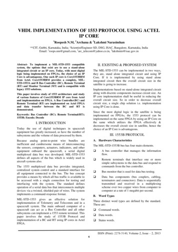
The layer two data link layer is fairly simple header and handshake protocol where theBC sends a “Command” word to direct the data transfers and to initiate minimal busmanagement commands (called “Mode Codes” – 1553’s version of an Ethernet SimpleNetwork Management Protocol, SNMP). The targeted RT will provide a “Status”response to complete the handshake of data or Mode Code (RTs do not respond to“Broadcast” messages – this is described later in this paper).1553 Command WordsBefore discussing message (packet) structures, a review of the three 1553 “word” typesis required. All 1553 words are 16 bit structures with a three bit sync and one bit oddparity (so 20 bit-times total). 1553 is a one mega bit bus so each word takes 20 µSecsof transmission time. A “Command Word” is the first word of every message sent by theBC: this word commands the RT to receive or transmit at a given “Subaddress” with aset number of “Data Words” transferred between the computers. Command Words witha unique subaddress value of zero 0 or 31, 0x1F, signifies that the Command Word isMode Code bus management command. The figure below details a Command Wordstructure.As shown in the figure, Command Words have a 5-bit field for the RT Address, whichmeans there are only 32 possible RT computers allowed on a 1553 network (for 1553Bcompliant systems, RT Address 31, 0x1F, is reserved to designate a Broadcast function– so only 31 unique RT computers are actually allowed). By their nature, Broadcastcommands are “transmit and forget” and receiving RTs do not respond. The Altaprotocol engines allow an option to disable Broadcast functio
1553 Tutorial and Reference MIL-STD-1553 (1553) is a standard that describes a one megabit serial network physical layer (layer one: physical layer – PHY) and message level protocol (layer two: data link layer). Primarily us