Transcription
MIL-STD-1553 TutorialMilesTek301 Leora Ln., Suite 100Lewisville, TX 750561-866-524-1553 www.milestek.com 2019 Infinite Electronics, Inc., MilesTek is a registered trademark of Infinite Electronics, Inc.
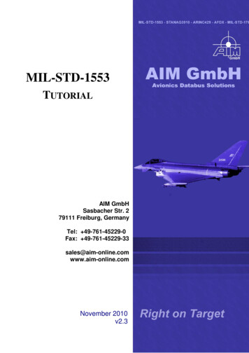
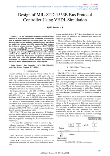
MIL-STD-1553 a Brief HistoryThe digital data bus was designed in the early 1970’s to replace analog point-to-point wire bundlesbetween electronic instrumentation. The latest version of the serial local area network (LAN) for militaryavionics, currently known as MIL-STD-1553B, was issued in 1978. After 35 years of familiarity andreliable products, the data bus continues to be a popular militarized networking solution.MIL-STD-1553B Bus ElementsA bus controller manages the information flow. Remote terminals interface with one or more simplesubsystems to the data bus and respond to commands from that bus controller. A bus monitor is used fortesting the data bus. The data bus is comprised of couplers, terminators, twinaxial cable assemblies andother accessories.Data Bus LAN TopologyBus couplers serve as coupling transformerswith fault-isolation resistors. Bus and/or stubterminators are used either at the end of the bus,or on individual stubs. 78 ohm twinax cablingis used with concentric twinax connectors (with acenter contact and an intermediate cylindricalcontact) to create the connecting cableassemblies.Box-Type Bus Coupler Configurations 1-8 stubsSingle, dual or non-terminatedAluminum or steel casingInline-Type Bus Coupler Configurations 1-4 stubs via M17/176-00002 cable leadsSingle, dual or non-terminatedwww.milestek.com 1-866-524-1553 2019 Infinite Electronics, Inc., MilesTek is a registered trademark of Infinite Electronics, Inc.2
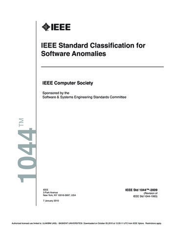
MIL-STD-1553B Data Bus RequirementsCommunications LineCable TypeCapacitanceTwistCharacteristic Ω (Z0)AttenuationBus LengthTerminationShieldingCable CouplingStub LengthStub VoltageCoupler TransformerTurns RatioDroopOvershoot & RingingCommon Mode RejectionFault ProtectionTwo-conductor twisted pair30 pF/ft. max.4 per ft. min.70 to 85 ohms @ 1 MHz1.5 dB/100 ft. @ 1 MHz maxNot specified2 ends terminated in resistors (Z0 2%)90% coverage minimum, 90% dual standby redundantUp to 20 ft. (may be exceeded)1 to 14V p-p amplitude, line-to-line min. signal voltage, transformer coupled1.41:1 20% at 27V p-p 250 kHz square wave 1V at 27V p-p 250 kHz square wave 45 dB @ MHz at 27V p-p 250 kHz sq. waveSeries resistors 0.75 (Z0 2%)Purpose & Application of Bus CouplersThe purpose of the bus coupler is to reduce reflections and maintain signal impedance levels. Sincedirectly coupled devices (without couplers) do not provide any DC isolation or common mode rejection,direct connection to the bus should be avoided. Should these directly coupled devices have any shortingfault between the internal isolation resistors (which are usually found on the circuit board) and the mainbus, the entire bus will experience failure because the device’s internal isolation resistors are notsufficient to ensure against the bus shorting out.The bus couplers have such built-in fault isolation resistors providing protection for the main bus in theevent of a short circuit in the stub. All devices, including the bus controller, bus monitor and remoteterminal, must be connected to the stub ends of the coupler.Both ends of the bus must be terminated with 78 ohm terminators, whether it includes a single coupler ora series of couplers connected together. Some couplers have built-in terminators and are generally usedat the end of the bus in multi-coupler applications. These types of couplers can be either single or dualterminated, and are mainly for vehicle applications, as they limit the flexibility of lab test set-ups. In a labapplication, the unused stub ports on the coupler do not need to be terminated since the stubs have ahigher impedance than the bus. A high impedance terminator (1000 to 3000 ohms) may be usedin vehicle applications to simulate a future load from an unspecified device. In both lab and vehicleapplications, an RFI cap over the unused stub is a deterrent to interference and dust.www.milestek.com 1-866-524-1553 2019 Infinite Electronics, Inc., MilesTek is a registered trademark of Infinite Electronics, Inc.3
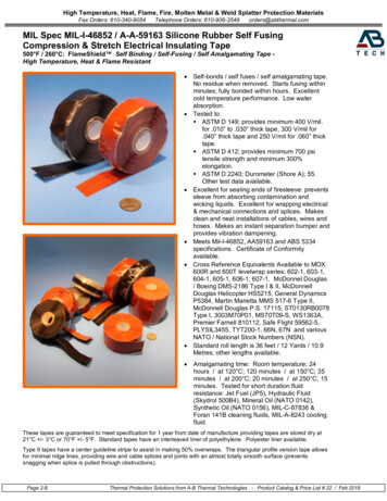
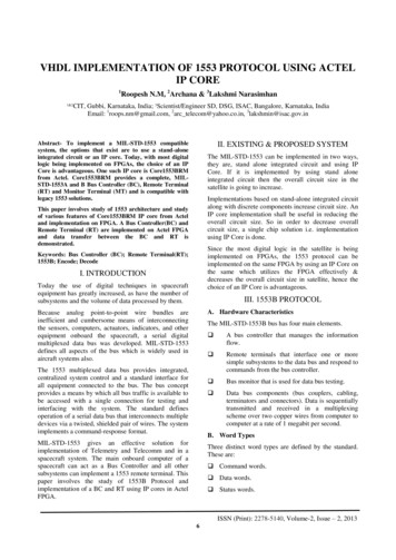
Bus Length ConsiderationsMIL-STD-1553B does not specify the length of the bus. That being said, the maximum length of the bus isdirectly related to the gauge of the cable conductor and time delay of the transmitted signal. A smallerconductor attenuates the signal more than a larger conductor. Typical propagation delay for a 1553Bcable is 1.6 nanoseconds per foot. Thus, a 100 ft. (end-to-end) bus would have a 160 nanosecondpropagation delay, which is equal to the average rise time of a 1553B signal. This delay time isproportional to the distance propagated. According to MIL-HDBK-1553A, when a signal’s propagationdelay time is more than 50% of the rise or fall time, it becomes necessary to consider transmission lineeffects.Waveform Characteristics (varying distance)Consideration must be given to the actual distance between the transmitter and receiver, as well as theindividual waveform characteristics of said transmitters and receivers.MIL-STD-1553B specifies that the longest stub length is 20 feet for transformer coupled stubs, but can beexceeded. With no stubs attached, the main bus acts as a transmission line with infinite length withoutdisturbing reflections. When a stub is added, the bus is loaded and a mismatch occurs with resultingreflections.The degree of mismatch and signal distortion due to reflections are a function of the impedancepresented by the stub and terminal input impedances. To minimize signal distortion, it is desirable that thestub maintain high impedances. This impedance is reflected back to the main bus, so at the sametime the impedances must be kept low so that an adequate amount of signal power can be delivered tothe receiving end. For this reason, a trade-off between these conflicting requirements is necessary toachieve the specified signal-to-noise ratio and system error rate performance (for more information, referto MIL-HDBK-155A).Cable TypeTypically, the cable used to connect the bus and stub devices has a characteristic impedance of 78 ohmsat 1 MHz. FEP and PFA jacket high-temperature cable are used in vehicles, while the PVC jacket cable ismore suitable for lab use.Connector TypesTRB - There are several types of connectors used on the bus and at the coupler stubs, the most commonof which is the concentric twinax connector. These connectors typically have three bayonet coupling slots(plugs) or lugs (jacks) known as TRB type, which have the same envelope size as a coaxial BNCconnector. The center contact is high (positive) connected to the twinax blue wire and the cylindricalcontact is low (negative) connected to the twinax white wire. The body of the connector is the bus shield.TRS - There is a subminiature version of the twinax concentric connector known as TRS type (sameenvelope size as TPS coaxial connectors).www.milestek.com 1-866-524-1553 2019 Infinite Electronics, Inc., MilesTek is a registered trademark of Infinite Electronics, Inc.4
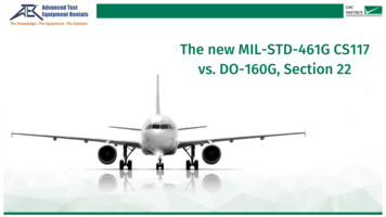
Common Mating Interface TypesTwo-bayonet, three-bayonet, four-bayonet, and threaded.Other Connector OptionsD-subminiature, cylindrical, andproprietary.Systems designers must be aware ofcable compatibility of connectors andavailability of components beforefinalizing the design of a data bussystem.MilesTek designs and manufactures a broad range of MIL-STD-1553B products to address MilitaryAvionics, Aerospace, Industrial and government applications. In addition to a wide selection of off theshelf products, MilesTek can custom manufacture cable assemblies and harnesses. MilesTek isheadquartered in Lewisville, Texas and is AS9100C and ISO9001:2008 certified.MilesTek is an Infinite Electronics companywww.milestek.com 1-866-524-1553 2019 Infinite Electronics, Inc., MilesTek is a registered trademark of Infinite Electronics, Inc.5
MIL-STD-1553 a Brief History The digital data bus was designed in the early 1970’s to replace analog point-to-point wire bundles between electronic instrumentation. The latest version of the serial local area network (LAN) for military avionics, currently known as MIL-STD-1553