Transcription
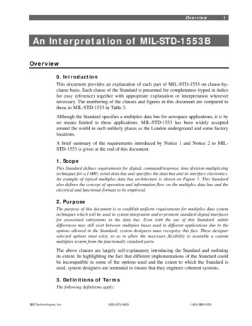
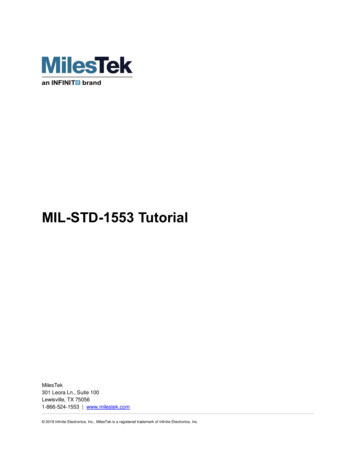
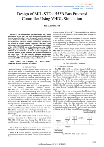
ISSN: 2278 – 909XInternational Journal of Advanced Research in Electronics and Communication Engineering (IJARECE)Volume4, Issue 7, July 2015Design of MIL-STD-1553B Bus ProtocolController Using VHDL SimulationSiji K, Saritha N R Abstract— The bus controller is a device which has a list ofaddresses of all bus users and sends a command to each one ofthem at a predetermined rate, giving each user the chance toaccess the data bus and send data required by other users. Databus architecture scheme is used for transferring data betweenthe devices in avionics systems. Nowadays, MIL-STD-1553Bbus system is used for this purpose. This paper presents designof the MIL-STD-1553B bus protocol controller using VHDL.This paper aims at design of 1553B protocol controller with theaddition of an arbitrator. It results in less complexity foraccessing memory by the processor and protocol controller atthe same time. This also provides memory managementmechanism. The proposed system is designed using finite statemachine in VHDL and simulated using ModelSim tool.Index Terms— Bus Controller (BC), MIL-STD-1553,ModelSim, Remote Terminal (RT), VHDL.I. INTRODUCTIONModern military avionics systems which contain lot ofdevices that needs to communicate with each other formeeting their requirement for a particular application. In theearlier days, point-to-point wiring schemes are used for thispurpose. But it became very complex, time consuming, bulkyand affects the performance of the system very badly. So, adata bus architecture scheme is used for communicatingbetween the devices in the avionics systems.In the present scenario, MIL-STD-1553B bus protocol isused for sharing information between devices.MIL-STD-1553 is a serial bus which was originallydeveloped by U.S Air force in 1973[1]. After some changesmade, an improved version MIL-STD-1553A was released in1975. Finally, it is modified to MIL-STD-1553B data bus andis used now in all avionics systems. It is a dual redundant bus,i.e., it has an alternative path in case of damage or failure. Thebidirectional MIL-STD-1553 bus which connects the devicesthrough a twisted shielded pair cable.MIL-STD-1553B data bus uses Manchester II bi-phaseencoding and decoding scheme because of its low error rate.Manchester coding has some advantages like easy errordetection, high noise immunity etc. It has transition in eachbit times[2].The data bus architecture which is shown in fig. 1explains a maximum of 32 devices can be connected to theMIL-STD-1553B data bus. Among these 32 devices, oneshould act as a bus controller (BC) and remaining as theremote terminal devices (RT). Bus controller is the only onedevice which can initiate all the communication through the1553 bus system[6].Most significant problem behind the existing bus protocolis the memory accessing. There may arise conflicts whileaccessing memory by both protocol controller and processor.To overcome this, the proposed system is designed with anarbitrator.This paper aims to design a bus protocol controller forMIL-STD-1553B data bus. The 1553 bus controller is knownas the 'heart of the system' since it controls all the activities inthe bus. The proposed system describes the 1553B busprotocol controller with an arbitrator, memory managementmechanism and a protocol controller.II. MIL-STD-1553 OVERVIEWA. 1553 Bus ArchitectureThe MIL-STD-1553B is a military standard which runs ona single twisted shielded pair of wires. It has a dual-redundantarchitecture and extremely low error rate of one word faultper 10 million words make MIL-STD-1553 a highly reliablebus. Only a single computer is allowed to transmit on the busat a given time. A 1553 bus system architecture is shown infig. 1 below. The device that controls all the communicationon the bus and acts as the master is called Bus Controller(BC) [1]. The BC can control multiple slave computers whichare called Remote Terminals (RT) by sending commands tothem.There may also be one or more passive Bus Monitors (BM)deployed on the bus which are only used to monitor or recordthe messages on the bus but can’t transmit any messages. Asshown in fig. 1, a maximum of thirty one remote terminalscan be connected to the bus in addition to the bus controller[2]. It consists of multiple computers having a master/slaverelationship. Only the bus controller can initiate atransmission on the bus. The RT receives and decodescommands from the bus controller and responds accordinglywithin the strictly defined time of 12 microseconds.Siji K, PG Scholar, Department of Electronics and CommunicationEngineering, Sree Buddha College of Engineering, Kerala, India.Saritha N R, Assistant Professor, Department of Electronics andCommunication Engineering, Sree Buddha College of Engineering, Kerala,India.Fig. 1 MIL-STD-1553B data bus architecture1901All Rights Reserved 2015 IJARECE
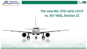
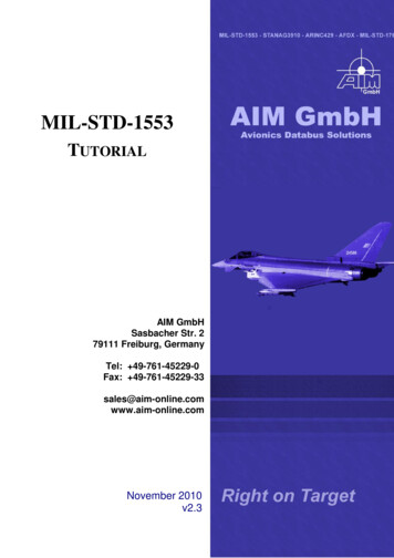
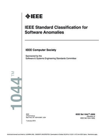
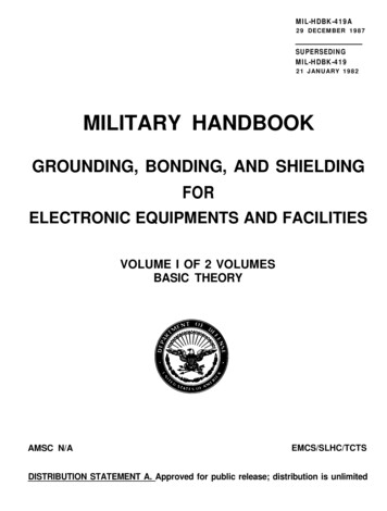
ISSN: 2278 – 909XInternational Journal of Advanced Research in Electronics and Communication Engineering (IJARECE)Volume4, Issue 7, July 2015An RT only performs transmission or reception of dataC. 1553 Message Formatswhen instructed to do so by the BC.MIL-STD-1553 has a proven history of providingThe BC is responsible for directing communications over extremely robust performance at 1 Mbps. The primarythe data bus. Although several of the systems connected to purpose of the 1553 data bus is to provide a common mediathe bus may have the ability to perform the role of BC. Only for the exchange of data between systems. All controlone BC is allowed to active at any given time and that only messages originate with the active bus controller and aremay issue commands over the data bus[2]. These commands received by a single receiver or by multiple receiversmay be related to the management of the bus or may be (broadcast). A command word with a terminal address valueoriented toward data communication to and from subsystems. of 31 (11111) indicates a broadcast message, while any otherterminal addresses are to identify unique messages to aB. 1553 Word Formatsterminal on the bus. The exchange of data is based onThere are three different words that form the messages thatmessage transmissions. A single message is the transmissionare transmitted on the bus; command word (CW), data wordof a command word, a status word, and a data word if they are(DW) and status word (SW) [3]. Each word is formed by aspecified.three-bit time sync, sixteen bits for the information fieldSole control of information transmission on the bus shallitself, and a parity bit at the end, which makes a total ofreside with the bus controller, which shall initiate alltwenty bits [5]. Fig. 2 shows an illustration of the three wordtransmissions. The 1553 standard defines different types offormats.information/message transmission formats [3]. All of theseEach bit is timed as one microsecond, resulting in oneformats are based on the three word types just defined. Heremegabit per second transmission rate for the bus. Thewe consider three important information formats which arecommunications between two elements in the data busshown in fig. 3. This information transfer formats are basedsystem, the bus controller and the remote terminal is allowedon the command/response philosophy in that all error freeonly through information transfer formats of 1553B bustransmissions received by a remote terminal are followed bywhich is shown in fig. 3. In 1553, the bus controller controlsthe transmission of a status word from the terminal to the busall communication and it is the sole device allowed tocontroller.transmit command words. Notice that all messages areThe bus controller to remote terminal (BC-RT) message isinitiated by the bus controller using command word.referred to as the receive command since the remote terminalThe actual information that is to be transferred through theis going to receive data [9]. The bus controller outputs a1553 bus is contained within the data word of a message [4].command word to the terminal defining the subaddress of theIt is transmitted by the bus controller after it sends a receivedata and the number of data words it is sending. The remotecommand or by the remote terminals after they receive aterminal upon validating the command word and all of thetransmit command. The sixteen bits of payload of the datadata words issues its status word within the response timeword is application specific and is defined by the interfacerequirements which is maximum of 12μs.designers. The standard only requires that the mostThe remote terminal to bus controller (RT-BC) message issignificant bit (MSB) of the data must be transmitted first.referred to as a transmit command. The bus controller issuesThe status of the remote terminal to the bus controller isonly a transmit command word to the remote terminal[9].indicated in the status word.The terminal, on validating the command word, transmits itsRemote terminals must send a status word as the first wordstatus word followed by the number of data words requestedof a response to a valid message from bus controller. Theby the command word.only time when a status word is suppressed is when theThe remote terminal to remote terminal (RT-RT)optional broadcast operation is performed .command allows a terminal (the data source) to transfer datadirectly to another terminal (the data sink) without goingthrough the bus controller. However, the bus controller mayalso collect the data and use them. (This is sometimes called aRT-RT-M command, since the Bus Controller monitors thedata). The bus controller issues a command word to thereceiving terminal immediately followed by a commandword to the transmitting terminal [9]. Here, the message shallinclude the two command words, the two status words, andthe data words.Fig. 2 1553 Word formats [5]1902All Rights Reserved 2015 IJARECE
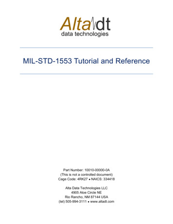
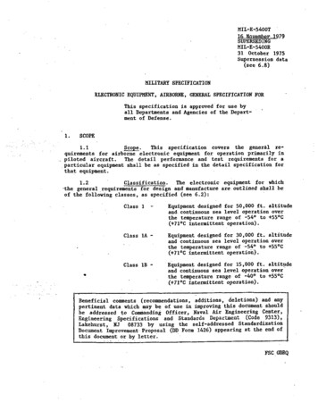
ISSN: 2278 – 909XInternational Journal of Advanced Research in Electronics and Communication Engineering (IJARECE)Volume4, Issue 7, July 2015Notes:# Inter Message Gap** Response TimeFig. 3 1553 Information transfer formatsIII. DESIGNA 1553B bus system is composed of a bus controller andone or more remote terminals, connected by the 1553B serialdata bus. Bus management is accomplished via a strictmaster-slave relationship between the BC and RTs. Toprovide multiple data paths for redundancy, a mission-criticalsystem typically utilizes several 1553B buses. All bustransmissions are accessible to all units connected to the bus,but only one unit can “speak” at a time. The BC initiates allbus transfers by sending a command word to individual RTs,and each RT is required to respond with a status messageacknowledging receipt of an error free BC’s message. Theentire control of the bus system is incorporated in the buscontroller. Thus the bus controller is said to be the heart of thesystem.Fig. 4 shows the overall block schematic representation ofproposed 1553B bus controller system. The bus controller isplaced in between the processor and the 1553 serial data bus.The entire block of the bus controller is incorporated withseveral other blocks such as Manchester encoder, Manchesterdecoder, arbitrator, block of memory, processor interfacelogic, protocol controller logic. All these blocks are designedas block by block basis using finite state machine in VHDL.B. Bus Controller DesignManchester II bi-phase encoding scheme is used by thisMIL-STD-1553B Bus system. Manchester encodingprovides a self-clocking waveform, that is, the clock isembedded in the data. So at the receiver side the clock can berecovered very easily. Manchester encoding encodes a “zero”with a low-to-high transition and a “one” with a high-to-lowtransition. It is easy to detect errors in Manchester encodingsince there exists a transition at each bit times [6].Manchester encoder requires a single clock with afrequency twice the desired data rate applied at the input ofencoder. Manchester decoder requires a single clock with afrequency of 12 times the desired data rate applied at thedecoder input. Decoder is free running and continuouslymonitors its data input lines for a valid sync character and twovalid Manchester data bits to start an output cycle.Manchester encoded data bits coming from the 1553 bus isdecoded and converted back to normal bits by using thedecoder.The bi-phase Manchester II encoder encodes the sixteenbits information fields of words. A logic "1" is represented bya 0.5 μs high to a 0.5 μs low transition, and a logic "0" isrepresented by the opposite low to high transition [9]. Asshown in figure 2, each word is preceded by a three-bit syncwhich is encoded as 1.5 μs low and 1.5 μs high for data wordsand opposite 1.5 μs high and 1.5 μs low for command andstatus words. The command word can be transmitted only bythe bus controller and as its name implies it contains acommand to the remote terminals which indicates either totransmit or receive the data words.Parallel to serial converter is used for converting theparallel data coming from the protocol control logic to serialdata since the 1553 bus is a serial bus. Memory access forboth protocol controller logic and processor is done throughan arbitrator. The arbitrator which is also known as amediator that helps to give access to the memory without anyconflicts between processor and protocol controller logic.A processor interface logic which is designed by using thefinite state machine in VHDL. With the help of this processorinterface logic, processor can also do its actions in parallelwhen it is used by the 1553 data bus. Processor need not waitfor the completion of data transmission in 1553 bus. A1kilobyte 16 bit RAM is also used to program the messagetransmission through the data bus.1903All Rights Reserved 2015 IJARECE
ISSN: 2278 – 909XInternational Journal of Advanced Research in Electronics and Communication Engineering (IJARECE)Volume4, Issue 7, July 2015Fig. 4 1553B Bus protocol controllerThe main block of this 1553 bus system is the protocolcontroller logic. It controls all the bus transmission throughthe 1553B data bus. In this work, the protocol controller logicis designed using finite state machine in VHDL which isshown in fig. 5.When the bc start signal is active, the protocol controllerstarts sending messages. Initially bus controller transmits thecommand word (CW). If the Transmit/Receive (T/R) signalis '1' which indicates the BC which tells to the RT to transmitthe data words. Upon receiving this command word, RTsends the status word (SW) followed by specified data words.If the Transmit/Receive (T/R) signal is '0' which indicates theBC which tells to the RT to receive the data words (DWs).Upon receiving the command word and data words from theBC, RT send the status word which indicates an error freereception.B. Design of Memory blockThe BC may be programmed to transmit multimessageframes. A single data transfer can transmit up to 32 messages.Each message may contain maximum of 34 words (32 datawords, 1 command word, 1 status word) and a minimum of 3words (1 data word, 1 command word, 1 status word). Thenumber of messages to be processed is programmable bymeans of the fixed message count location in the sharedRAM. Memory block in the proposed system describes astack area of shared RAM to store the message details. Stackarea maintains the details of every message that aretransmitted through the bus. Each message resides in adesignated message block area of the shared RAM. Stackpointer points to the block status address of every message. Inthe memory block, the value of stack pointer is incrementedby three and value of the message counter is decremented byone at the end of each message processed.IV. RESULTSFig. 5 State diagram of protocol controllerThe designed state machine has been simulated usingModelSim and obtained waveform is shown in fig. 6 below.1904All Rights Reserved 2015 IJARECE
ISSN: 2278 – 909XInternational Journal of Advanced Research in Electronics and Communication Engineering (IJARECE)Volume4, Issue 7, July 2015Fig. 6 Simulated waveform of 1553B bus controllerA finite state machine which designed the enhancedthroughput message activity in a 1553B based bus controllerhave been presented. The proposed system works as a buscontroller which controls the data transfer through the bus.For BC to RT transfer a command word followed by dataword is send by the BC. Upon receiving this, RT sends SWindicating an error free reception. The RT to BC transferincludes a command word which is send by the BC and uponreceiving this CW, RT sends status word followed by the dataword.V. CONCLUSION & FUTURE WORKSThis paper describes a MIL-STD-1553B serial data businterface and the bus protocol controller VHDL simulation.The 1553B bus protocol controller which helps in controllingthe data transmission through the bus. In the proposedsystem, 1553B bus controller is modeled as a finite statemachine in VHDL. With the addition of an arbitrator,memory block and protocol controller, the performance ofthe entire system was improved. Since all the componentsneeded for the bus controller was integrated as a singleblock, its area of utilization is reduced.For future work, it may be possible to implement theMIL-STD-1553B bus controller onto a Xilinx based FPGAplatform. It is expected to improve the performance of thesystem to a great extent, by varying any of the parameterssuch as delay, speed etc of bus controller. Compared to otheravionics data bus standards 1553B is known for its reliabilityand flexibility.REFERENCES[1] Department of Defence, "MIL-STD-1553B, Aircraft internaltime-division multiplexing data bus", Washington,D.C.,1978.[2] Data Device Corporation, (2003,August) "MIL-STD-1553Designer's guide", Bohemia, NY, 2003.[3] Jemti Jose and Sharone Varghese, “Design of 1553 protocolcontroller for reliable data transfer in aircrafts”, InProceedings of the 12th InternationalConferenceonIntelligent Systems Design and Applications (ISDA 2012),Cochin, India, pp 686-691.[4] MIL-STD-1553A Multiplex Applications Handbook, 1988,Washington, D.C., Department of Defense.[5] J. Furgerson, "MIL-STD-1553 Tutorial", AIM-Avionics DataBus Solutions, U.K, November 2010.[6] Jemti Jose, “Design of Manchester II bi-phase encoder forMIL- STD 1553 protocol”, In Proceedings of the IEEEInternational Multi Conference on Automation, Computing,Control, CommunicationandCompressedSensing(iMac4s), Kerala, India, March 2013, in press (notindexed).[7] Carey B. R (2007, Dec), Avionics magazine, [online].Available: http://www.AvionicsToday.com[8] D.R Bracknell, "Introduction to the MIL-STD-1553B serialmultiplex data bus", Ministry of Defence, September 1988.[9] Jemti Jose, "An FPGA Implementation of 1553 ProtocolController", International Journal of Computer InformationSystems and Industrial Management Applications, ISSN2150-7988 Vol. 6 (2014) pp. 66-76.1905All Rights Reserved 2015 IJARECE
ISSN: 2278 – 909XInternational Journal of Advanced Research in Electronics and Communication Engineering (IJARECE)Volume4, Issue 7, July 2015Author's ProfileSiji K was born in Kerala, India in 1990. She is currently pursingMaster of Technology (M Tech) inEmbedded systems in Sree BuddhaCollege of Engineering, Alappuzha. Shereceived her Bachelor of Technology(B.Tech) degree in Electronics andCommunication Engineering from KeralaUniversity, Trivandrum, India in 2012.Her areas of interest include Embeddedsystem design, FPGA based design andmobile communications.Saritha N R was born in Kerala, India in 1983. She received herB.Sc. Electronics in 2003 and M.Sc.electronics in 2005 from M.G University,Kottayam, India. She completed herMaster of Technology (M.Tech) in 2008from M.G University, Kottayam, India.She has teaching experience of about 7years and is currently the AssistantProfessor in the Department ofElectronicsandCommunicationEngineering in Sree Buddha College ofEngineering, Alappuzha. Her main areasof interest are signal processing,nanoelectronics and optoelectronics.1906All Rights Reserved 2015 IJARECE
1975. Finally, it is modified to MIL-STD-1553B data bus and is used now in all avionics systems. It is a dual redundant bus, i.e., it has an alternative path in case of damage or failure. The bidirectional MIL-STD-1553 bus which connects the devices through a twisted shielded pair cable. MI