Transcription
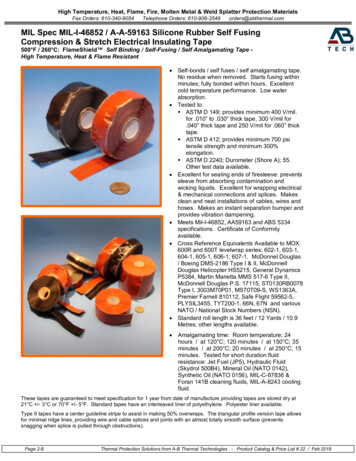
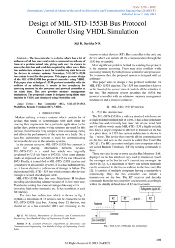
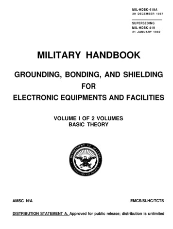
Overview1An Interpretation of MIL-STD-1553BOverview0. IntroductionThis document provides an explanation of each part of MIL-STD-1553 on clause-byclause basis. Each clause of the Standard is presented for completeness (typed in italicsfor easy reference) together with appropriate explanation or interpretation wherevernecessary. The numbering of the clauses and figures in this document are compared tothose in MIL-STD-1553 in Table 3.Although the Standard specifies a multiplex data bus for aerospace applications, it is byno means limited to these applications. MIL-STD-1553 has been widely acceptedaround the world in such unlikely places as the London underground and some factorylocations.A brief summary of the requirements introduced by Notice 1 and Notice 2 to MILSTD-1553 is given at the end of this document.1. ScopeThis Standard defines requirements for digital, command/response, time division multiplexingtechniques for a I MHz serial data bus and specifies the data bus and its interface electronics.An example of typical multiplex data bus architecture is shown on Figure 1. This Standardalso defines the concept of operation and information flow on the multiplex data bus and theelectrical and functional formats to be employed.2. PurposeThe purpose of this document is to establish uniform requirements for multiplex data systemtechniques which will be used in system integration and to promote standard digital interfacesfor associated subsystems to the data bus. Even with the use of this Standard, subtledifferences may still exist between multiplex buses used in different applications due to theoptions allowed in the Standard; system designers must recognize this fact. These designerselected options must exist, so as to allow the necessary flexibility to assemble a custommultiplex system from the functionally standard parts.The above clauses are largely self-explanatory introducing the Standard and outliningits extent. In highlighting the fact that different implementations of the Standard couldbe incompatible in some of the options used and the extent to which the Standard isused, system designers are reminded to ensure that they engineer coherent systems.3. Definitions of TermsThe following definitions apply:SBS Technologies, Inc(505) 875-06001-800-SBS-1553
2An Overview of MIL-STD-1553BAsynchronous operation. For the purpose of this Standard, asynchronous operation is the useof an independent clock source in each terminal for message transmission. Decoding isachieved in receiving terminals using clock information derived from the message.Bit. Contraction of binary digit: may be either zero or one. In information theory, a binarydigit is equal to one binary decision or the designation of one of two possible values or statesof anything used to store or convey information.Bit rate. The number of bits transmitted per second.Broadcast. Operation of a data bus system such that information is transmitted by the buscontroller or a remote terminal for reception by all terminals using the broadcast modeaddress.Bus controller (BC). The terminal assigned the task of initiating information transfers on thedata bus.Bus monitor (BM). The terminal assigned the task of listening to bus traffic and extractingselected information to be used at a later time.Command/Response. Operation of a data bus system such that remote terminals receive andtransmit data only when commanded to do so by the bus controller.Data bus. Whenever a data bus or bus is referred to in this document it shall imply all thehardware including screened twisted pair cables, isolation resistors, transformers, etc.,required to provide a single data path between the bus controller and all the associatedremote terminals.Dynamic bus control. The operation of a data bus system in which designated terminals areoffered control of the data bus.Half duplex. Operation of a data transfer system in either direction over a single line, but notin both directions on that line simultaneously.Message. A single message is the transmission of a command word, status word, and datawords if they are specified. For the case of a remote terminal to remote terminal (RT to RT)transmission, the message shall include the two command words, the two status words, andthe data words.Mode code. A means by which the bus controller can communicate with the multiplex busrelated hardware, in order to assist in the management of information flow.Pulse code modulation (PCM). The form of modulation in which the modulation signal issampled, quantized, and coded so that each element of information consists of different typesor number of pulses and spaces.Redundant data bus. The use of more than one data bus to provide more than one data pathbetween the subsystems, i.e., dual redundant data bus, tri-redundant data bus, etc.Remote terminal (RT). All terminals not operating as the bus controller or as a bus monitor.Subsystem. The device or functional unit receiving data transfer service from the data bus.SBS Technologies, Inc(505) 875-06001-800-SBS-1553
General Requirements3Terminal. The electronic module necessary to interface the data bus with the subsystem andthe subsystem with the data bus. Terminals may exist as separate line replaceable units(LRU's) or be contained within the elements of the subsystem.Time division multiplexing (TDM). The transmission of information from several signalchannels through one communication system with different channel samples staggered in timeto form a composite pulse train.Word. In this document a word is a sequence of 16 bits plus a synchronization signal (sync)(three bit times) and one bit parity.Definition of terms. Although the above definitions include some generally acceptedterms, definitions of word size, message content, and data bus system terminology arespecific to this MIL-STD.General Requirements4. Test and Operating RequirementsAll specified requirements shall be valid over the environmental conditions in which themultiplex data bus system shall be required to operate.This clause is included to specify that the environmental conditions in which the bus isto operate are determined by the vehicle in which it is placed. The environmental limitsof operation will be largely determined by the terminal components and their enclosure.5. Data Bus OperationThe multiplex data bus system in its most elementary configuration shall be as shown onFigure 1. The data bus shall function asynchronously in a command/response mode, andtransmission shall occur in a half-duplex manner. Sole control of information transmission onthe bus shall reside with the bus controller, which shall initiate all transmissions. Theinformation flow on the data bus shall be comprised of messages which are, in turn, formedby three types of words (command, data, and status) as defined in clauses 13-16.6. Data FormDigital data may be transmitted in any desired form, provided that the chosen form shall becompatible with the message and word formats defined in this Standard. Any unused bitpositions in a word shall be transmitted as logic zeros.7. Bit PriorityThe most significant bit shall be transmitted first with the less significant bits following indescending order of value in the data word. The number of bits required to define a quantityshall be consistent with the resolution or accuracy required. In the event that multipleprecision quantities (information accuracy or resolution requiring more than 16 bits) aretransmitted, the most significant bits shall be transmitted first, followed by the word(s)containing the lesser significant bits in numerically descending order. Bit packing of multiplequantities in a single data word is permitted.SBS Technologies, Inc(505) 875-06001-800-SBS-1553
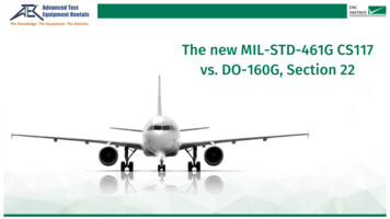
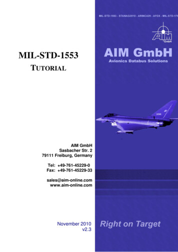
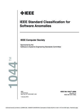
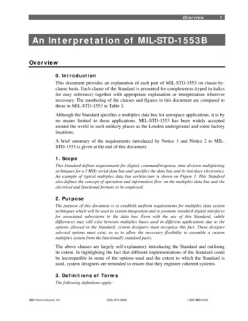
4An Overview of emoteTerminalSubsystemwith EmbeddedRemote TerminalSubsystem(s)Figure 1: Typical Data Bus ArchitectureSingle bit data and other parameters which are characterized by bit patterns of fewerthan 16 bits will not fill the 16 bits of data allowed in data word format. Twoapproaches can be adopted to use all the bits in a word:1. Packing multiple parameters in a word2. Filling in zeros for all unused bitsIn the first approach the encoding and decoding complexity must be considered, whilein the second approach the inefficiency of sending as little as one bit/word must beconsidered.Transmission Methods8. ModulationThe signal shall be transferred over the data bus in serial digital pulse code modulation form.Baseband modulation was chosen in view of its advantages over carrier modulationtechniques which need a greater bandwidth of transmitting media and more complexterminal hardware.9. Data CodeThe data code shall be Manchester 1I bi-phase level. A logic one shall be transmitted as abipolar coded signal 110 (i.e., a positive pulse followed by a negative pulse). A logic zeroshall be bipolar coded signal 011 i.e., a negative pulse followed by a positive pulse). Atransition through zero occurs at the midpoint of each bit time (see Figure 2).SBS Technologies, Inc(505) 875-06001-800-SBS-1553
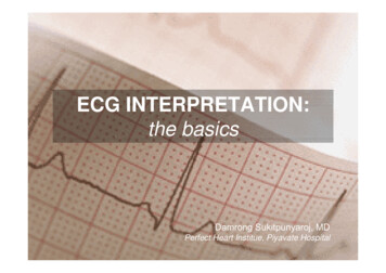
Transmission Methods5Like polar Return to Zero (RZ), Bi-phase Level consists of a self-clocking waveformand is well-suited to applications in which bit synchronization cannot be conveyed byother means. Unlike Polar RZ, Bi-phase level is compatible with transformer coupling,and may, therefore, be used to convey data via the primary transmission medium. Biphase level is most appropriate for use on short transformer-coupled local buses, or onthe transformer-coupled primary transmission medium when bit synchronizationinformation is conveyed by the signaling waveform and cannot be provided via aseparate channel.OneBitTime( )-(0)-( )-(0)-( )-(0)-(-)-1 MHz Clock*NRZ Data1Manchester II011000Bi-Phase LevelNote*NRZ-Non return to zeroFigure 2: Data EncodingWith the Bi-phase Level data code, signal inversion can be caused by reversedconnection of the data bus signal conductors.10. Transmission Bit RateThe transmission bit rate on the bus shall be 1.0 megabit per second with a combinedaccuracy and long-term stability of 0.1%. The short-term stability (i.e., accuracy over 1.0 sinterval) shall be at least 0.01%.11. Word SizeThe word size shall be 16 bits plus the synchronization signal (sync) and the parity bit for atotal of 20 bit times as shown on Figure 3.12. Word FormatsThe word formats shall be as shown in Figure 3 for the command, data, and status words. Aspecification of each format is given in clauses 13-16.The 20-bit word size represents the number of bit times for a word of 16 data bits,three bit time sync pattern and one bit time for a single parity bit. The three bit timesync pattern is described in clause 13.2.SBS Technologies, Inc(505) 875-06001-800-SBS-1553
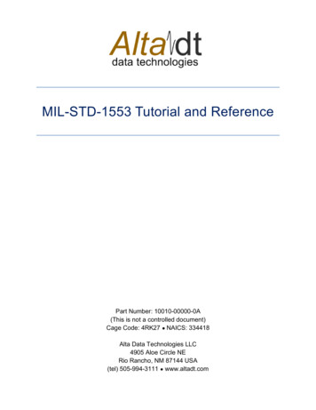
6An Overview of eTerminal Address91011151617181920551T/RData WordCount/Mode CodeP161DataPMessage ErrorInstrumentationService RequestReserved11111Terminal FlagRemoteTerminal Address3Dynamic Bus Control Acceptance1Subsystem Flag1Busy1Broadcast Command Received5NoteT/R - Transmit/ReceiveP - rd121PFigure 3: Word FormatsWord Formats13. Command Words13.1 ContentA command word shall consist of a synchronization signal (sync), RT address,transmit/receive bit, subaddress/mode, data word count/mode code, and parity bit (see Figure3).13.2 SyncThe command sync waveform shall be an invalid Manchester waveform as shown on Figure 4.The width shall be three bit times, with the waveform being positive for the first one and halfbit times, and then negative for the following one and a half bit times. If the next bit followingthe sync is a logic zero, then the last half of the sync wave form will have an apparent width oftwo bit times due to the Manchester encoding. Volts0- VoltsWord SyncAddressBit (1)Figure 4: Command and Status Sync WaveformSBS Technologies, Inc(505) 875-06001-800-SBS-1553
Word Formats713.3 Remote Terminal (RT) AddressThe next five bits following the sync shall be the RT address. Each RT shall be assigned to aunique address. Decimal address 31 (11111) shall not be assigned as a unique address. Inaddition to its unique address, a RT shall be assigned decimal address 31 (11111) as thecommon address, if the broadcast option is used.Each remote terminal is assigned a unique address for which it is responsible to respondwhen that address is transmitted as part of a command word on the data bus by theactive bus controller. It should be noted that decimal address 31 cannot be assigned asa unique address. This address has been assigned to all remote terminals as the commonaddress for which they may receive broadcast data if the system uses the broadcastoption (see clause 24).13.4 Transmit/ReceiveThe next bit following the address shall be the transmit/receive (TIR) bit, which shall indicatethe action required of the RT. A logic zero shall indicate the RT is to receive, and logic oneshall indicate the RT is to transmit.13.5 Subaddress/ModeThe next five bits following the transmit/receive bit shall be used for either an RT subaddressor mode control, as is dictated by the individual terminal requirements. The subaddress/modevalues of 00000 and 11111 are reserved for special purposes, as specified in clause 13.8, andshall not be used for any other functions.This field has two mutually exclusive functions:1. It identifies the subaddress of specific messages to a remote terminal.2. It identifies that a mode command is being transmitted.The use of either 00000 or 11111 in the subaddress/mode field is decoded to indicatethat a mode code command is present in the next five bit field. In this case thesubaddress range will be limited to 30 unique addresses. It is recommended that 11111is used to invoke mode control in order to allow distinction to be made betweencommand and status words as described in the explanation of clause 15.5. If theinstrumentation bit in the status word is implemented, the subaddress will be limited to15 unique subaddresses. The requirements for use of the instrumentation bit are definedin clause 15.5.The subaddress identification can serve to identify one of a number of subsystemsconnected to a single RT, alternatively it may be used as pointer to specific storelocations in a single subsystem. It should be noted that by using the T/R bit, amaximum of 30 transmit and 30 receive subaddresses are available if theinstrumentation bit is not used.13.6 Data Word Count/Mode CodeThe next five bits following the subaddress/mode control shall be the quantity of data words tobe either sent out or received by the RT or the optional mode code as specified in clause 13.8.SBS Technologies, Inc(505) 875-06001-800-SBS-1553
8An Overview of MIL-STD-1553BA maximum of 32 data words may be transmitted or received in any one message block. All1's shall indicate a decimal count of 31, and all 0's shall indicate a decimal count of 32.The dual function of this field provides for the identification of message lengths for datamessages or mode codes for managing the information transfer system. The five bitfield allows up to 32 data words to be transmitted in a message or 32 specified modecodes. As zero word count data cannot be sent, five bits can specify up to 32 datawords.13.7 ParityThe last bit in the word shall be used for parity over the preceding sixteen bits. Odd parityshall be used.The use of single parity bit per word is provided to identify any single or odd bit errorsoccurring during the transmission and detection of a word.The total number of bits in any word, including the parity bit, should be odd. Only oneparity bit is used as it is considered that this, together with the protection provided byuse of Manchester II encoding and the word synchronization field, gives adequateintegrity. However, if a greater degree of integrity is required, additional error checkingcapability may be incorporated in the data, such as Cyclic Redundancy Checks (CRC)or Checksums.13.8 Optional Mode ControlFor RT's exercising this option a subaddress/mode of 00000 or 11111 shall imply that thecontents of the data word count/mode code field are to decoded as a five bit mode command.The mode codes shall only be used to communicate with the multiplex bus related hardwareand to assist in the management of information flow, and not to extract data from or feed datato a functional subsystem. Code 00000 to 01111 shall only be used for mode codes which donot require transfer of a data word. For these mode codes, the TIR bit shall be set to 1. Codes10000 to 11111 shall only used for mode codes which require transfer of a single data word.For these mode codes, the TIR bit shall indicate the direction of data word flow as specified inclause 13.4. No multiple data word transfer shall be implemented with any mode code. Themode codes are reserved for the specific functions shown in Table 1 and shall not be used forany other purpose. If the designer chooses to implement any of these functions, the specificcodes, TIR bit assignment, and the use of data word, shall be used as indicated. The use of thebroadcast command option shall only be applied to particular mode codes as specified inTable 1.Mode commands are used to manage the data bus system and are considered anecessary overhead to assist in the control of the data flow. The overheads comprisecommand words and status words. Command and status words are associated withboth control messages and data messages. Message formats within this protocol can betransmitted to a single receiver or to multiple receivers based upon the command wordaddress for the message.Although the Standard states that the optional mode control function should not beused to extract data from or feed data to a functional subsystem, the extent of RTfunctions and hence those of subsystems can vary. There are also cases where modeSBS Technologies, Inc(505) 875-06001-800-SBS-1553
Word Formats9commands may reflect back into the subsystem, for instance a broadcast sync commandcould be used to revert to a specific state or time (e.g., sync to weapon firing mode).None of the mode codes are mandatory. Some RTs may not handle all mode codes. Useof those not implemented should provide an illegal command response (see clause30.4).Within the command word, the mode codes provide a data bus management capability.The mode codes have been divided into two groups: mode codes without a data word(00000 - 01111) and mode codes with a data word (10000 - 11111). The use of bit 15in the command word to identify the two groups was provided to aid in the decodingprocess. Also, the use of a single data word instead of multiple data words was adoptedto simplify the mode circuitry within RT's. Generally, with these two groups of modecommand, all management requirements of an information transfer system can be met.Some mode codes in each of these two groups are reserved for future use (see clauses13.8.10 and 13.8.17).Table 1 provides a list of assigned mode codes indicating (in column d) whether or nota data word is associated with each mode code. In some cases e.g., transmit lastcommand, the data word is associated with the response from the RT to a receive modecommand rather than with the transmit mode command. This is shown in the examplesof all types of mode command transfer formats given in Figure 13.Table 1: Assigned Mode 00100Dynamic Bus ControlSynchronizeTransmit StatusInitiate Self TestTransmitter 10100001001Override Transmitter ShutdownInhibit Terminal Flag BitOverride Inhibit Terminal Flag BitReset Remote 11ReservedNoTBD*ReservedTransmit Vector WordSynchronizeTransmit Last CommandTransmit Built In Test WordSelected Transmitter ShutdownOver
2 An Overview of MIL-STD-1553B SBS Technologies, Inc (505) 875-0600 1-800-SBS-1553 Asynchronous operation . For the purpose of this Standard, asynchronous operation is the use of an independent clock source in each terminal for message transmission. Decoding is achieved in receiving terminals using clock information derived from the message. Bit .File Size: 482KB