Transcription
USAMIL-STD-1553TUTORIALAIM GmbHSasbacher Str. 279111 Freiburg, GermanyTel: 49-761-45229-00Fax: comNovember 2010v2.3
USAMIL-STD-1553 Tutorialv1.3December 2002
GmbHAIM WorldwideAIM GmbHSasbacher Str. 279111 Freiburg, Germany 49-761-45 22 90sales@aim-online.comAIM-USASeven Neshaminy InterplexSuite 211Trevose, PA 19053267-982-26001-877-5201553salesusa @aim-online.comMunich Sales OfficeTerofalstrasse 23 a80689 Muenchen, Germany 49-89-70 92 92 92salesgermany@aim-online.comAIM UKLincoln Rd, Cressex Business ParkBucks HP12 3RB, England 44-1494-44 68 44salesuk@aim-online.comNotice: The information that is provided in this document is believed to be accurate.Noresponsibility is assumed by AIM for its use. No license or rights are granted by implicationin connection therewith. Specifications are subject to change without notice. Copyright 2001-2002 : AIMii
GmbHDOCUMENT HISTORYThe following table defines the history of this document.The description ofchanges/enhancements made to each version is defined in general terms.Version Cover DateCreated byDescription1.01.11.21.32.3Pat FrodymaPat FrodymaPat FrodymaJ. FurgersonB. WaldmannCreation of documentFormat EditsEdits to Word DescriptionsFormat/Edits/Incorporation of Notice 1-4 in textUpdate addressesMay 26, 2001May 2001Feb 2002Dec 2002Nov 2010iii
GmbHTHIS PAGE INTENTIONALLY LEFT BLANKiv
GmbHTABLE OF CONTENTSTitlePageINTRODUCTION.1-1About This Manual .1-1Applicable Documents.1-2MIL-STD-1553 OVERVIEW .2-1MIL-STD-1553 History and Application .2-11553B Hardware Components.2-4Bus Controller.2-4Remote Terminal .2-4Bus Monitor .2-51553 Cabling .2-51553 Coupling .2-5Direct Coupling.2-6Transformer Coupling.2-6Bus Topology .2-7MIL-STD-1760C .2-81553 Test Procedures.2-9Developmental Testing .2-9Design Verification.2-9Production Testing.2-9Systems Integration Testing.2-9Field/Operational Testing .2-10MIL-STD-1553B SPECIFICATION INTERPRETATION.3-11. Scope.3-11.1 Scope.3-11.2 Application.3-12. Referenced Documents .3-22.1 Issue of Document .3-23. Definitions .3-34. General Requirements.3-54.1Test and Operating Requirements .3-54.2Data Bus Operation .3-54.3Characteristics .3-64.3.1 Data form.3-64.3.2 Bit Priority.3-64.3.3 Transmission Method.3-74.4Terminal Operation .3-324.4.1 Common Operation .3-324.4.2 Bus Controller Operation .3-33v
GmbH4.4.3 Remote Terminal.3-334.4.4 Bus Monitor Operation.3-364.5Hardware Characteristics .3-364.5.1 Data Bus Characteristics .3-364.5.2 Terminal Characteristics .3-41Appendix.3-4810. General.3-4820. Referenced Documents .3-5030. General Requirements.3-50NOTES .4-1Acronyms and Abbreviations .4-1Definition of Terms .4-2APPENDIX A - NOTICES APPLIED TO MIL-STD-1553B.10-1Notice 1 Overview .10-1Notice 2 Overview .10-1Notice 3 Overview .10-2Notice 4 Overview .10-2vi
GmbHLIST OF 123-133-10.13-10.2TitlePageBus Components .3-1Data Encoding .3-7Word Formats.3-8Command and Status Sync.3-9Data Sync .3-16Information Transfer Formats .3-23Broadcast Information Transfer Formats .3-24Intermessage Gap and Response Time.3-30Data Bus Interface Using Transmforer Coupling.3-31Data Base Interface Using Direct Coupling .3-31Coupling Transmformer.3-38Terminal Input/Output Characteristics for Transformer Coupled Stubs andDirect Coupled Stubs .3-41Output Waveform.3-45Possible Redundancy.3-48Possible Redundancy.3-48LIST OF 3A and MIL-STD-1553B Requirements Comparison.2-31553 Cable Characteristics .2-51553 Test Plans for all Components . 2-10Assigned Mode Codes . 3-11Criteria for Acceptance or Rejection of a Terminal for the Noise RejectionTest. 3-44vii
GmbHTHIS PAGE INTENTIONALLY LEFT BLANKviii
IntroductionGmbHINTRODUCTIONAbout This ManualThis manual was developed to provide a general overview of MIL-STD-1553 itsspecifications and applications.The first chapter provides a discussion of MIL-STD-1553, its history, application andoperational overview. Included is a reference to MIL-STD-1760C as it applies to WeaponStores Interface and its relationship to MIL-STD-1553B.The second chapter includes a complete annotated version of the MIL-STD-1553Bspecification and an interpretation of the specification contents. The specification is on thetop of each page and the AIM interpretation is located on the lower portion of the page.Notices 1 though 4, addendums to the MIL-STD-1553B specification, are summarized at theend of this manual, and have been incorporated into the specification discussed within thisdocument.AIM provides Commercial-Off-The-Shelf (COTS) products to design, produce, integrate, testand troubleshoot all systems and capabilities mentioned in this MIL-STD-1553 Tutorial aswell as for ARINC 429, STANAG 3910, MIL-STD-1760 Applications and Panavia SerialLink. Supported hardware platforms include PC/AT, PCI, Compact PCI, VME, VXI, andPMC.AIM software products also support full Remote Terminal production testing, full busanalysis and complete system emulation and test capabilities per MIL-STD-1553Bspecifications.For detailed information on AIM solutions, visit www.aim-online.com or emailsalesusa@aim-online.com.MIL-STD-1553 Tutorial1-1
IntroductionGmbHApplicable DocumentsThe following documents shall be considered to be a part of this document to the extentspecified herein.Industry DocumentsMIL-STD-464, Electromagnetic Environmental Effects Requirements for Systems, March 18,1997MIL-HDBK-1553A, Multiplex Application Handbook, March 23, 1995MIL-STD-1553B, Department of Defense Interface Standard for Digital Time DivisionCommand/Response Multiplex Data Bus, Notice 1-4, January 1996MIL-STD-1760C, Interface Standard for Aircraft/Store Electrical Interconnection System,March 2, 1999SAE AS4111, Validation Test Plan for the Digital Time Division Command/ResponseMultiplex Data Bus Remote Terminals, October 1998SAE AS4112, Production Test Plan for the Digital Time Division Command/ResponseMultiplex Data Bus Remote Terminals, January 1989SAE AS4113, Validation Test Plan for the Digital Time Division Command/ResponseMultiplex Data Bus Controllers, January 1989SAE AS4114, Production Test Plan for the Time Division Command/Response MultiplexData Bus Controllers, January 1989SAE AS4115,, Test Plan for the Digital Time Division Command/Response Multiplex DataBus System, January 1989SAE AS4116, Test Plan for the Digital Time Division Command/Response Multiplex DataBus Bus Monitors, September 1990SAE AS4117, Test Plan for the Digital Time Division Command/Response Multiplex DataBus Couplers, Terminators, and Data Bus Cables, March 1991AIM Product Specific DocumentsNone1-2MIL-STD-1553 Tutorial
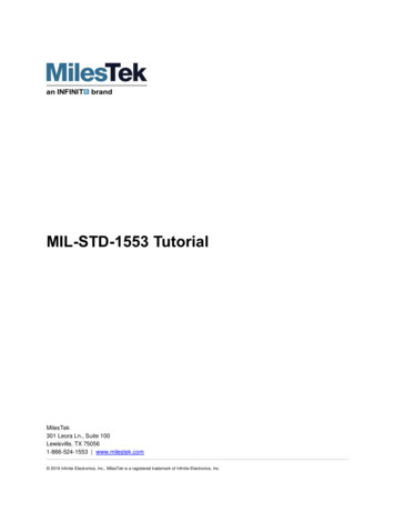
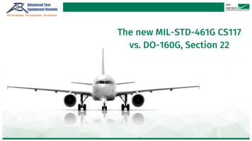
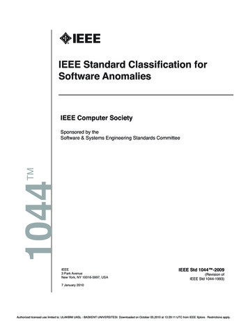
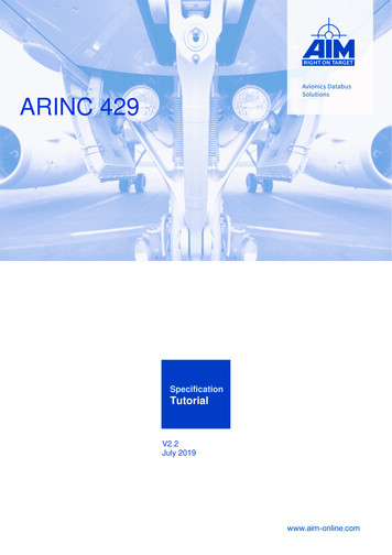
MIL-STD-1553 OverviewGmbHMIL-STD-1553 OVERVIEWMIL-STD-1553B is the military specification defining a Digital Time DivisionCommand/Response Multiplexed Data Bus. The 1553 databus is a dual-redundant, bidirectional, Manchester II encoded databus with a high bit error reliability. All buscommunications are controlled and initiated by a main bus controller. Remote terminaldevices attached to the bus respond to controller commands.MIL-STD-1553B defines specifications for terminal device operation and coupling, wordstructure and format, messaging protocol andelectrical characteristics.MIL-STD-1553 History and ApplicationMIL-STD-1553B was developed from the growingcomplexity of integrated avionics systems and thesubsequent increase in the number of discreteinterconnects between terminal devices. Directpoint-to-point wiring became complex, expensivePoint-to-Point Wiring Schemeand bulky, requiring definition of a multiplex databus standard. The first draft of a standard in 1968by the Aerospace Branch of the Society of Automotive Engineers (SAE) laid the foundationfor the US Air Force’s adoption of MIL-STD-1553 in 1973.A tri-service version, MIL-STD-1553A was released in 1975, modified to MIL-STD-1553Bin 1978 and utilized in the Air Force F-16 and the United States (US) Army AH-64A ApacheAttack Helicopter. Notice 2, released in 1986 and superceded Notice 1 released in 1980, is atri-service standard for RT design specs and defines how some bus options are to be used.Notices 3 and 4 did not alter the contents of the standard, but only provided a title change.MIL-STD-1553B has become the internationally accepted networking standard for integratingmilitary platforms. Table 2-I shows the differences between MIL-STD-1553A and MILSTD-1553B.Data Bus ArchitectureMilitary services and contractors originallyadopted MIL-STD-1553 as an avionics databus due to its highly reliable, serial, 1 Megabitper sec (Mbps) transfer rate and extremely lowerror rate of 1 word fault per 10 million words,on a dual-redundant architecture.This reliability has proven equally effective oncommunication networks in submarines, tanks,target drones, missile and satellite systems,land-based and launch vehicles, and space system including the current International SpaceStation and Shuttle programs.MIL-STD-1553 Tutorial2-1
MIL-STD-1553 OverviewGmbHMIL-STD-1553B defines the data bus structure for interconnection of up to 31 remoteterminal (RT) devices. A single controller device on the bus initiates the command/responsecommunication with the remote devices. The remote and control devices are interconnectedover two, separate buses. Normal operation involves only the primary bus with the secondarybus available as redundant backup in the event of primary bus damage or failure.Standardization of a set of specifications for a military data bus provides two majoradvantages:2-2a.Significant size/weight savings of interconnected devices and cablingb.Reduced development and modification costs with compatible devices.MIL-STD-1553 Tutorial
MIL-STD-1553 OverviewGmbHTable 2-I MIL-STD-1553A and MIL-STD-1553B Requirements ComparisonSpecification RequirementCable TypeMIL-STD-1553AMIL-STD-1553BCable Shield Coverage – minimumCable Twist – minimumCapacitance, wire to wire – maximumCharacteristic Cable Impedance (ZO)Jacketed, shielded twistedpair80%12 twists/foot30 pF/ft70 Ω 10% @ 1 MHzCable AttenuationCable LengthCable Termination1 dB/100 ft @ 1 MHz300 ft – maximumCharacteristic ImpedanceCable StubbingCable Coupling ShieldCoupling Transformer Turns RatioDirect Coupling 1 ftTransformer Coupling1 – 20 ftShielded coupler boxUnspecifiedTransformer Open Circuit ImpedanceUnspecifiedTransformer Waveform IntegrityUnspecifiedTransformer Common ModeRejectionFault IsolationIsolation Resistors in serieswith couplerDirect CoupledImpedance across bus with failedTransformer couplingcomponentDirect couplingStub Voltage RequirementTransformer CoupledDirect CoupledUnspecifiedJacketed, shielded twistedpair75%4 twists/foot30 pF/ft70-80 Ω 10% @ 1 MHzNominal1.5 dB/100 ft @ 1 MHzUnspecifiedNominal CharacteristicImpedance 2%Direct Coupling 1 ftTransformer Coupling 1 –20 ft75% coverage – minimum1:141 3% with higherTurns on isolation resistorside3 kΩ from 75 kHz – 1 MHzWith 1 V RMS sine waveDroop of 20% overshoot –maxRinging of 1 V peak –max45 dB @ 1 MHzR 0.75 ZO 5%R 0.75 ZO 2%R 0.75 ZO 5%R 55 Ω 2%No less than 1.5 ZONo less than 1.5 ZOUnspecifiedNo less than 110 Ω1 V to 20 V peak to peak1 V to 20 V peak to peak1 V to 14 V peak to peak1.4 V to 20 V peak to peakMIL-STD-1553 Tutorial2-3
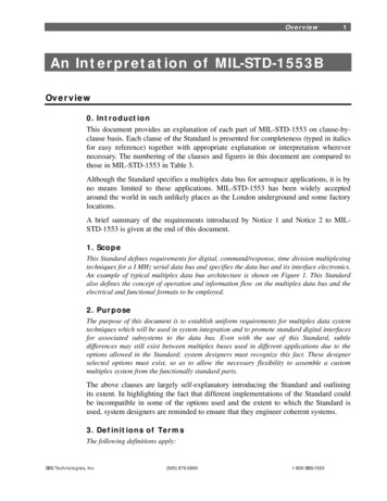
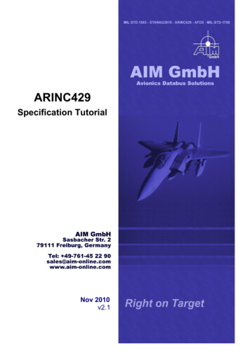
MIL-STD-1553 OverviewGmbH1553B Hardware ComponentsMIL-STD-1553B defines three types of terminal devices that are allowed on the bus:a.Primary Bus (A)Bus Controller (BC)Secondary Bus (B)b.Remote Terminal (RT)c.Bus Monitor itorBus ControllerThe main function of the bus controller (BC) is to provide data flow control for alltransmissions on the bus. In addition to initiating all data transfers, the BC must transmit,receive and coordinate the transfer of information on the data bus. All information iscommunicated in command/response mode - the BC sends a command to the RTs, whichreply with a response.The bus controller, according to MIL-STD-1553B, is the “key part of the data bus system”and “the sole control of information transmission on the bus shall reside with the buscontroller, which shall initiate all transmission”. The bus can support multiple BCs, but onlyone can be active at a time.Normal BC data flow control includes transmitting commands to RTs at predetermined timeintervals. The commands may include data or requests for data (including status) from RTs.The BC has control to modify the flow of bus data based on changes in the operatingenvironment. These changes could be a result of an air-to-ground attack mode changing toair-to-air, or the failure mode of a hydraulic system. The BC is responsible for detectingthese changes and initiating action to counter them. Error detection may require the BC toattempt communications to the RT on the redundant, backup bus.Remote TerminalThe remo
MIL-STD-1553 Overview MIL-STD-1553 Tutorial MIL-STD-1553B defines the data bus structure for interconnection of up to 31 remote terminal (RT) devices. A single controller device on the bus initiates the command/response communication with the remote devices. The remote and control devices are interconnected over two, separate buses.File Size: 519KBPage Count: 82Explore furtherII. REVIEW AND RATIONALE OF MIL-STD-1553A AND MIL-STD-1553B.www.milstd1553.comMIL-STD-1553 B AIRCRAFT INTERNAL TIME DIVISION MULTIPLEXeveryspec.comMILSTD1553.com Complete Online Reference for MIL-STD-1553www.milstd1553.comMIL-STD-1553 Tutorial & Intelligent Products Excalibur .www.mil-1553.comMIL-STD-1553 - Wikipediaen.wikipedia.orgRecommended to you b