Transcription
ARINC429Specification TutorialNov 2010v2.1
GmbHPage 2
GmbHDocument HistoryVersion1.01.12.1Cover DateJuly 2001July 2001Nov 2010Created byPat FrodymaPat FrodymaB. WaldmannDescriptionCreation of DocumentEdit contentUpdate addressesAIM WorldwideAIM GmbHSasbacher Str. 279111 Freiburg, Germany 49-761-45 22 90sales@aim-online.comMunich Sales OfficeTerofalstrasse 23 a80689 Muenchen, Germany 49-89-70 92 92 .comSeven Neshaminy InterplexSuite 211Trevose, PA 19053267-982-26001-877-5201553salesusa @aim-online.comAIM UKLincoln Rd, Cressex Business ParkBucks HP12 3RB, England 44-1494-44 68 44salesuk@aim-online.comARINC 429 TutorialPage 3
GmbHAbout this ManualThis manual was developed to provide a general overview of the ARINC 429Specification, its characteristics and applications. The ARINC 429 Specification is acopywritten document owned by Aeronautical Radio, Inc. who is responsible for itsmodification and distribution.This manual refers predominately to Part 1 of the 429 Specification outlining thefunctional description, electrical characteristics and word formats. Complete and currentcopies of the Specification can be obtained from Aeronautical Radio, Inc. Contactinformation is made available on page 23 of this manual.AIM provides Commercial-Off-The-Shelf (COTS) products to design, produce, integrate,test and troubleshoot all systems and capabilities mentioned in this ARINC 429 TutorialManual as well as for MIL-STD-1553 A./B, STANAG 3910 and PANAVIA configurations.AIM software products also support full Remote Terminal production testing, full busanalysis and complete system emulation and test capabilities per ARINC429specifications.For detailed information on AIM solutions, visit www.aim-online.com or emailsales@aim-online.com.NoticeThe information that is provided in this document is believed to be accurate. Noresponsibility is assumed by AIM for its use. No license or rights are granted byimplication in connection therewith. Specifications are subject to change without notice. Copyright 2001 : AIMPage 4
GmbHARINC 429 Tutorial ManualTable of ContentsAbout this Manual4ARINC 429 Specification Overview7Overview of ARINC7History of ARINC 4298The ARINC 429 Specification9Cable Characteristics10Transmission Characteristics11Waveform Parameters12Word Formats13Parity13SSM13Data15Data Types16SDI17Label18Attachments to the ARINC 429 Specification19ARINC Contact Information21ARINC 429 TutorialPage 5
GmbHPage 6
GmbHARINC 429 Specification OverviewThe ARINC 429 Specification defines the standard requirements for the transfer ofdigital data between avionics systems on commercial aircraft. ARINC 429 is also knownas the Mark 33 DITS Specification. Signal levels, timing and protocol characteristics aredefined for ease of design implementation and data communications on the Mark 33Digital Information Transfer System (DITS) bus.ARINC 429 is a privately copywritten specification developed to provideinterchangeability and interoperability of line replaceable units (LRUs) in commercialaircraft. Manufacturers of avionics equipment are under no requirement to comply to theARINC 429 Specification, but designing avionics systems to meet the design guidelinesprovides cross-manufacturer interoperability between functional units.Overview of ARINCARINC stands for Aeronautical Radio, Inc., a private corporation organized in 1929, andis comprised of airlines, aircraft manufacturers and avionics equipment manufacturersas corporate shareholders. ARINC was developed to produce specifications andstandards for avionics equipment outside the government for domestic and overseasmanufacturers.ARINC copywrites and publishes standards produced by the Airlines ElectronicEngineering Committee (AEEC). The AEEC is an international standards organizationmade up of major airline operators, avionics industry manufacturers and ARINCmembers.The AEEC sets standards for avionics equipment and systems and provides industrydefined requirements for standardization of form, fit and function between variousmanufacturers products.ARINC publishes the AEEC produced standards under three types of documents:1. ARINC CharacteristicsCharacteristics are definitions of the form, fit and function of avionics equipment.These documents are equipment specific and define how a unit will operate. TheARINC 500 Series of Characteristics define older analog avionics equipmentwhere the ARINC 700 Series are more current documents and are typically digitalversions of the analog specs.400 Series documents are general design and support documentation for the 500Series avionics equipment characteristics.600 Series documents are general design and support documentation for the 700Series avionics equipment characteristics.ARINC 429 TutorialPage 7
GmbH2. ARINC SpecificationsSpecifications are used to definePhysical packaging and mounting of avionics equipmentData communications standardsHigh level computer languagesThe ARINC 429 Specification, Mark 33 Digital Information Transfer System fallsunder the Specification document category.3. ARINC ReportsReports provide general information and best practice guidelines for airlines.Reports predominately refer to maintenance and support procedures.History of ARINC 429The ARINC 429 Specification developed out of the original commercial aviation digitalcommunication spec, the ARINC 419 Specification. The ARINC 419, first released in1966 and last revised in 1983, describes four different wiring topologies, including aserial, twisted shielded pair interface used by the Digital Air Data System (DADS),known as the ARINC 575 or DADS 575 Spec.This serial topology evolved into the ARINC 429 Specification, first released as ARINC429-1 in April 1978, and currently exists as ARINC 429-15. ARINC 429-15 was adoptedby the AEEC in 1995 and is comprised of 3 parts:ARINC Specification 429, Part 1-15: Functional Description, ElectricalInterface, Label Assignments and Word FormatsARINC Specification 429, Part 2-15: Discrete Word Data StandardsARINC Specification 429, Part 3-15: File Data Transfer TechniquesPart 1 addresses the buses physical parameters, label and address assignments, andword formats.Part 2 defines the formats of words with discrete word bit assignments.Part 3 defines link layer file data transfer protocol for data block and file transfers.Page 8
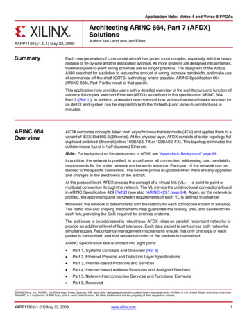
GmbHThe ARINC 429 SpecificationThe ARINC 429 Specification establishes how avionics equipment and systemscommunicate on commercial aircraft. The specification defines electrical characteristics,word structures and protocol necessary to establish bus communication. ARINC 429utilizes the simplex, twisted shielded pair data bus standard Mark 33 Digital InformationTransfer System bus.ARINC 429 defines both the hardware and data formats required for bus transmission.Hardware consists of a single transmitter – or source – connected to from 1-20 receivers– or sinks – on one twisted wire pair. Data can be transmitted in one direction only –simplex communication – with bi-directional transmission requiring two channels orbuses. The devices, line replaceable units or LRUs, are most commonly configured in astar or bus-drop topology. Each LRU may contain multiple transmitters and receiverscommunicating on different buses. This simple architecture, almost point-to-point wiring,provides a highly reliable transfer of data.Star RxTxLRUTxReceivingLRURxRxTxRxTxARINC 429 TutorialLRUReceivingLRURxRxRxRxMultiple BusDesignPage 9
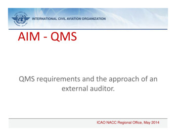
GmbHA transmitter may ‘talk only’ to a number of receivers on the bus, up to 20 on one wirepair, with each receiver continually monitoring for its applicable data, but does notacknowledge receipt of the data.A transmitter may require acknowledgement from a receiver when large amounts of datahave been transferred. This handshaking is performed using a particular word style, asopposed to a hard wired handshake. When this two way communication format isrequired, two twisted pairs constituting two channels are necessary to carry informationback and forth, one for each direction.Transmission from the source LRU is comprised of 32 bit words containing a 24 bit dataportion containing the actual information, and an 8 bit label describing the data itself.LRUs have no address assigned through ARINC 429, but rather have Equipment IDnumbers which allow grouping equipment into systems, which facilitates systemmanagement and file transfers.Sequential words are separated by at least 4 bit times of null or zero voltage. By utilizingthis null gap between words, a separate clock signal is unnecessary. Transmission ratesmay be at either a low speed – 12.5 kHz – or a high speed – 100kHz.Cable CharacteristicsThe transmission bus media uses a 78 Ω shielded twisted pair cable. The shield mustbe grounded at each end and at all junctions along the bus.Line ATransmitterReceiverShieldGroundLine BTo ReceiverThe transmitting source output impedance should be 75 Ω 5 Ω divided equallybetween Line A and Line B. This balanced output should closely match the impedanceof the cable. The receiving sink must have an effective input impedance of 8k Ωminimum.Maximum length is not specified, as it is dependent on the number of sink receivers,sink drain and source power. Most systems are designed for under 150 feet, butconditions permitting, can extend to 300 feet and beyond.Page 10
GmbHTransmission CharacteristicsARINC 429 specifies two speeds for data transmission. Low speed operation is stated at12.5 kHz, with an actual allowable range of 12 to 14.5 kHz. High speed operation is 100kHz 1% allowed. These two data rates can not be used on the same transmission bus.Data is transmitted in a bipolar, Return-to-Zero format. This is a tri-state modulationconsisting of HIGH, NULL and LOW states.Transmission voltages are measured across the output terminals of the source.Voltages presented across the receiver input will be dependent on line length, stubconfiguration and the number of receivers connected. The following voltage levelsindicate the three allowable states:TRANSMITSTATERECEIVE 10.0 V 1.0 V0 V 0.5V-10.0 V 1.0 VHIGHNULLLOW 6.5 to 13 V 2.5 to -2.5 V-6.5 to -13 VIn bipolar, Return-to-Zero – or RZ – format, a HIGH (or 1) is achieved with thetransmission signal going from NULL to 10 V for the first half of the bit cycle, thenreturning to zero or NULL.A LOW (or 0) is produced by the signal dropping from NULL to –10 V for the first half bitcycle, then returning to zero.With a Return-to-Zero modulation format, each bit cycle time ends with the signal levelat 0 Volts, eliminating the need for an external clock, creating a self-clocking signal.An example of the bipolar, tri-state RZ signal is shown here:1 bit timeHIGHNULLLOWData RepresentedARINC 429 Tutorial10110Page 11
GmbHWaveform ParametersPulse rise and fall times are controlled by RC circuits built into ARINC 429 transmitters.This circuitry minimizes overshoot ringing common with short rise times. Allowable riseand fall times are shown below for both bit rates. Bit and ½ bit times are also defined.1 bit time½ bit time90%10%RiseTimeHigh SpeedFallTimeLow SpeedBit Rate100 kbps 1%12 – 14.5 kbps 1%1 bit time10 µsec 2.5%(1/Bit rate) µsec 2.5%½ bit time5 µsec 5%(1 bit time/2) 5%Rise Time1.5 µsec 0.5 µsec10 µsec 5 µsecFall Time1.5 µsec 0.5 µsec10 µsec 5 µsecPage 12
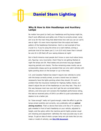
GmbHWord FormatsARINC 429 protocol uses a point-to-point format, transmitting data from a single sourceon the bus to up to 20 receivers. The transmitter is always transmitting, either datawords or the NULL state. Most ARINC messages contain only one data word consistingof either Binary (BNR), Binary Coded Decimal (BCD) or alphanumeric data encodedusing ISO Alphabet No. 5. File data transfers that send more than one word are alsoallowed.ARINC 429 data words are 32 bit words made up of five primary fields:Parity – 1 bitSign/Status Matrix (SSM) – 2 bitsData – 19 bitsSource/Destination Identifier (SDI) – 2 bitsLabel – 8 61514Data131211LSB109SDI876543LabelARINC 429 32 bit Word FormatThe only two fields definitively required are the Label and the Parity bit, leaving up to 23bits available for higher resolution data representation. Many non-standard word formatshave been adopted by various manufacturers of avionics equipment. Even with thevariations included, all ARINC data is transmitted in 32 bit words. Any unused bits arepadded with zeros.ParityARINC 429 defines the Most Significant Bit (MSB) of the data word as the Parity bit.ARINC uses odd parity as an error check to insure accurate data reception. The numberof Logic 1s transmitted in each word is an odd number, with bit 32 being set or clearedto obtain the odd count. ARINC 429 specifies no means of error correction, only errordetection.Sign/Status MatrixBits 31-30 are assigned as the Sign/Status Matrix field or SSM. Depending on the wordsLabel, which indicates which type of data is being transmitted, the SSM field can providedifferent information. (See page 15 for more information on data types.) This field can beused to indicate sign or direction of the words data, or report source equipmentoperating status and is dependant on the data type.ARINC 429 TutorialPage 1321
GmbHFor Binary Coded Decimal data – BCD – theSSM can be used to indicate the sign ordirection of the data contained in the ARINCword.3130Use of the sign function for BCD data isoptional. If not used, the SSM bits should bepadded – set to zero.00110101BCD data SSM Sign CodingBITDecoded InformationPlus, North, East, Right, To, AboveNo Computed DataFunctional TestMinus, South, West, Left, From, BelowThe No Computed Data code (01) is used toidentify a source system that is not able to produce reliable data.The Functional Test code
ARINC 429 Tutorial Page 11 GmbH Transmission Characteristics ARINC 429 specifies two speeds for data transmission. Low speed operation is stated at 12.5 kHz, with an actual allowable range of 12 to 14.5 kHz. High speed operation is 100 kHz 1% allowed. These two data rates can not be used on the same transmission bus. .File Size: 1MBPage Count: 21