Transcription
ARINC 429SpecificationTutorialV2.2July 2019
DOCUMENT HISTORYVersionCover DateCreated byDescription2.12.2Nov 2010July 2019B. WaldmannB. WaldmannUpdate addressesUpdate CIAIM WorldwideAIM GmbHSasbacher Str. 2D-79111 Freiburg / GermanyPhone 49 (0)761 4 52 29-0Fax 49 (0)761 4 52 29-33sales@aim-online.comAIM GmbH – Munich Sales OfficeTerofalstr. 23aD-80689 München / GermanyPhone 49 (0)89 70 92 92-92Fax 49 (0)89 70 92 92-94salesgermany@aim-online.comAIM UK OfficeCressex Enterprise Centre, Lincoln Rd.High Wycombe, Bucks. HP12 3RB / UKPhone 44 (0)1494-446844Fax 44 (0)1494-449324salesuk@aim-online.comAIM USA LLCSeven Neshaminy InterplexSuite 211 Trevose, PA 19053Phone 267-982-2600Fax comARINC 429 Tutorial2
About this ManualThis manual was developed to provide a general overview of the ARINC 429Specification, its characteristics and applications. The ARINC 429 Specification is acopywritten document owned by Aeronautical Radio, Inc. who is responsible for itsmodification and distribution.This manual refers predominately to Part 1 of the 429 Specification outlining thefunctional description, electrical characteristics and word formats. Complete andcurrent copies of the Specification can be obtained from Aeronautical Radio, Inc.Contact information is made available on page 23 of this --------------------AIM provides Commercial-Off-The-Shelf (COTS) products to design, produce,integrate, test and troubleshoot all systems and capabilities mentioned in thisARINC 429 Tutorial Manual as well as for MIL-STD-1553 A./B, STANAG 3910 andPANAVIA configurations.AIM software products also support full Remote Terminal production testing, full busanalysis and complete system emulation and test capabilities per ARINC 429specifications.For detailed information on AIM solutions, visit www.aim-online.com or emailsales@aim-online.com.Notice: The information that is provided in this document is believed to be accurate.No responsibility is assumed by AIM GmbH for its use. No license or rights are granted byimplication in connection therewith. Specifications are subject to change without notice. AIM GmbH 2019ARINC 429 Tutorial3
ARINC 429 Tutorial ManualTable of ContentsAbout this Manual .3ARINC 429 Specification Overview .5Overview of ARINC .5History of ARINC 429.6The ARINC 429 Specification .7Cable Characteristics .8Transmission Characteristics .9Waveform Parameters .10Word Formats .11Parity.11SSM .11Data .13Data Types .14SDI .15Label .16Attachments to the ARINC 429 Specification .17ARINC Contact Information .19ARINC 429 Tutorial4
ARINC 429 Specification OverviewThe ARINC 429 Specification defines the standard requirements for the transfer ofdigital data between avionics systems on commercial aircraft. ARINC 429 is alsoknown as the Mark 33 DITS Specification. Signal levels, timing and protocolcharacteristics are defined for ease of design implementation and datacommunications on the Mark 33 Digital Information Transfer System (DITS) bus.ARINC 429 is a privately copywritten specification developed to provideinterchangeability and interoperability of line replaceable units (LRUs) in commercialaircraft. Manufacturers of avionics equipment are under no requirement to comply tothe ARINC 429 Specification, but designing avionics systems to meet the designguidelines provides cross-manufacturer interoperability between functional units.Overview of ARINCARINC stands for Aeronautical Radio, Inc., a private corporation organized in 1929,and is comprised of airlines, aircraft manufacturers and avionics equipmentmanufacturers as corporate shareholders. ARINC was developed to producespecifications and standards for avionics equipment outside the government fordomestic and overseas manufacturers.ARINC copywrites and publishes standards produced by the Airlines ElectronicEngineering Committee (AEEC). The AEEC is an international standardsorganization made up of major airline operators, avionics industry manufacturers andARINC members.The AEEC sets standards for avionics equipment and systems and provides industrydefined requirements for standardization of form, fit and function between variousmanufacturers products.ARINC publishes the AEEC produced standards under three types of documents:1. ARINC CharacteristicsCharacteristics are definitions of the form, fit and function of avionicsequipment. These documents are equipment specific and define how a unitwill operate. The ARINC 500 Series of Characteristics define older analogavionics equipment where the ARINC 700 Series are more currentdocuments and are typically digital versions of the analog specs.400 Series documents are general design and support documentation for the500 Series avionics equipment characteristics.600 Series documents are general design and support documentation for the700 Series avionics equipment characteristics.ARINC 429 Tutorial5
2. ARINC SpecificationsSpecifications are used to define Physical packaging and mounting of avionics equipmentData communications standardsHigh level computer languagesThe ARINC 429 Specification, Mark 33 Digital Information Transfer Systemfalls under the Specification document category.3. ARINC ReportsReports provide general information and best practice guidelines for airlines.Reports predominately refer to maintenance and support procedures.History of ARINC 429The ARINC 429 Specification developed out of the original commercial aviationdigital communication spec, the ARINC 419 Specification. The ARINC 419, firstreleased in 1966 and last revised in 1983, describes four different wiring topologies,including a serial, twisted shielded pair interface used by the Digital Air Data System(DADS), known as the ARINC 575 or DADS 575 Spec.This serial topology evolved into the ARINC 429 Specification, first released asARINC 429-1 in April 1978, and currently exists as ARINC 429-15. ARINC 429-15was adopted by the AEEC in 1995 and is comprised of 3 parts: ARINC Specification 429, Part 1-15: Functional Description,Electrical Interface, Label Assignments and Word Formats ARINC Specification 429, Part 2-15: Discrete Word Data Standards ARINC Specification 429, Part 3-15: File Data Transfer TechniquesPart 1 addresses the buses physical parameters, label and address assignments,and word formats.Part 2 defines the formats of words with discrete word bit assignments.Part 3 defines link layer file data transfer protocol for data block and file transfers.ARINC 429 Tutorial6
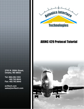
The ARINC 429 SpecificationThe ARINC 429 Specification establishes how avionics equipment and systemscommunicate on commercial aircraft. The specification defines electricalcharacteristics, word structures and protocol necessary to establish buscommunication. ARINC 429 utilizes the simplex, twisted shielded pair data busstandard Mark 33 Digital Information Transfer System bus.ARINC 429 defines both the hardware and data formats required for bustransmission. Hardware consists of a single transmitter – or source – connectedto from 1-20 receivers – or sinks – on one twisted wire pair. Data can be transmittedin one direction only – simplex communication – with bi-directional transmissionrequiring two channels or buses. The devices, line replaceable units or LRUs,are most commonly configured in a star or bus-drop topology. Each LRU maycontain multiple transmitters and receivers communicating on different buses.This simple architecture, almost point-to-point wiring, provides a highly reliabletransfer of data.Star TopologyReceivingLRUReceivingLRUBus-Drop ceivingLRUReceivingLRUMultiple Bus DesignReceivingLRURxLRUTxTxLRRxUTxRxRxTxRxARINC 429 TutorialRxRxRx7
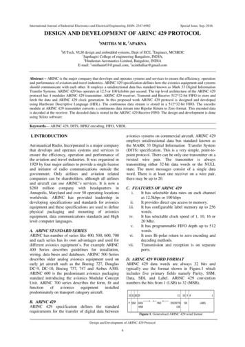
A transmitter may ‘talk only’ to a number of receivers on the bus, up to 20 on onewire pair, with each receiver continually monitoring for its applicable data, but doesnot acknowledge receipt of the data.A transmitter may require acknowledgement from a receiver when large amounts ofdata have been transferred. This handshaking is performed using a particular wordstyle, as opposed to a hard wired handshake. When this two way communicationformat is required, two twisted pairs constituting two channels are necessary to carryinformation back and forth, one for each direction.Transmission from the source LRU is comprised of 32-bit words containing a 24-bitdata portion containing the actual information, and an 8-bit label describing the dataitself. LRUs have no address assigned through ARINC 429, but rather haveEquipment ID numbers which allow grouping equipment into systems, whichfacilitates system management and file transfers.Sequential words are separated by at least 4-bit times of null or zero voltage. Byutilizing this null gap between words, a separate clock signal is unnecessary.Transmission rates may be at either a low speed – 12.5 kHz – or a high speed –100kHz.Cable CharacteristicsThe transmission bus media uses a 78 Ω shielded twisted pair cable. The shieldmust be grounded at each end and at all junctions along the bus.Line ATransmitterReceiverShieldGroundLine BTo ReceiverThe transmitting source output impedance should be 75 Ω 5 Ω divided equallybetween Line A and Line B. This balanced output should closely match theimpedance of the cable. The receiving sink must have an effective input impedanceof 8k Ω minimum.Maximum length is not specified, as it is dependent on the number of sink receivers,sink drain and source power. Most systems are designed for under 150 feet, butconditions permitting, can extend to 300 feet and beyond.ARINC 429 Tutorial8
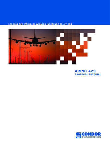
Transmission CharacteristicsARINC 429 specifies two speeds for data transmission. Low speed operation isstated at 12.5 kHz, with an actual allowable range of 12 to 14.5 kHz. High speedoperation is 100 kHz 1% allowed. These two data rates can not be used on thesame transmission bus.Data is transmitted in a bipolar, Return-to-Zero format. This is a tri-state modulationconsisting of HIGH, NULL and LOW states.Transmission voltages are measured across the output terminals of the source.Voltages presented across the receiver input will be dependent on line length, stubconfiguration and the number of receivers connected. The following voltage levelsindicate the three allowable states:TRANSMITSTATERECEIVE 10.0 V 1.0 VHIGH 6.5 to 13 V0 V 0.5 VNULL 2.5 to -2.5 V-10.0 V 1.0 VLOW-6.5 to -13 VIn bipolar, Return-to-Zero – or RZ – format, a HIGH (or 1) is achieved with thetransmission signal going from NULL to 10 V for the first half of the bit cycle, thenreturning to zero or NULL.A LOW (or 0) is produced by the signal dropping from NULL to –10 V for the first halfbit cycle, then returning to zero.With a Return-to-Zero modulation format, each bit cycle time ends with the signallevel at 0 Volts, eliminating the need for an external clock, creating a self-clockingsignal.An example of the bipolar, tri-state RZ signal is shown here:1 bit timeHIGHNULLLOWData RepresentedARINC 429 Tutorial1109
Waveform ParametersPulse rise and fall times are controlled by RC circuits built into ARINC 429transmitters. This circuitry minimizes overshoot ringing common with short rise times.Allowable rise and fall times are shown below for both bit rates. Bit and ½ bit timesare also defined.1 bit time½ bit timeRiseFallHigh SpeedLow SpeedBit Rate100 kbps 1%12 – 14.5 kbps 1%1 bit time10 µsec 2.5%(1/Bit rate) µsec 2.5%½ bit time5 µsec 5%(1 bit time/2) 5%Rise Time1.5 µsec 0.5 µsec10 µsec 5 µsecFall Time1.5 µsec 0.5 µsec10 µsec 5 µsecARINC 429 Tutorial10
Word FormatsARINC 429 protocol uses a point-to-point format, transmitting data from a singlesource on the bus to up to 20 receivers. The transmitter is always transmitting, eitherdata words or the NULL state. Most ARINC messages contain only one data wordconsisting of either Binary (BNR), Binary Coded Decimal (BCD) or alphanumeric dataencoded using ISO Alphabet No. 5. File data transfers that send more than one wordare also allowed.ARINC 429 data words are 32-bit words made up of five primary fields: Parity – 1-bitSign/Status Matrix (SSM) – 2-bitsData – 19-bitsSource/Destination Identifier (SDI) – 2-bitsLabel – 8-bitsMSBLSB32 31 30 29 28 27 26
ARINC 429 Tutorial 9 Transmission Characteristics ARINC 429 specifies two speeds for data transmission. Low speed operation is stated at 12.5 kHz, with an actual allowable range of 12 to 14.5 kHz. High speed operation is 100 kHz 1% allowed. These two data rates can not be used on the same transmission bus. Data is transmitted in a bipolar, Returnto-Zero format. This is a tri- -state .File Size: 1MBPage Count: 19Explore furtherARINC 429 Tutorial - ARINC 429 Specification Overview .www.aim-online.comARINC 429 - Wikipediaen.wikipedia.orgARINC Protocol Tutorial - INSYDEleonardodaga.insyde.itDESIGN AND DEVELOPMENT OF ARINC 429 PROTOCOLpep.ijieee.org.inARINC 429 Tutorial & Products Excalibur Systemswww.mil-1553.comRecommended to you based on what's popular Feedback