Transcription
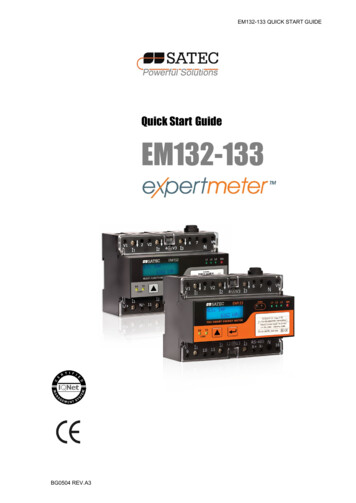
PM180PM180 SeriesSUBSTATION AUTOMATION UNITOPERATION MANUALBG0525 Rev. A7
LIMITED WARRANTYThe manufacturer offers the customer a 24-month functional warranty on the instrument for faultyworkmanship or parts from date of dispatch from the distributor. In all cases, this warranty is validfor 36 months from the date of production. This warranty is on a return to factory basis.The manufacturer does not accept liability for any damage caused by instrument malfunction. Themanufacturer accepts no responsibility for the suitability of the instrument to the application forwhich it was purchased.Failure to install, set up or operate the instrument according to the instructions herein will void thewarranty.Only a duly authorized representative of the manufacturer may open your instrument. The unitshould only be opened in a fully anti-static environment. Failure to do so may damage the electroniccomponents and will void the warranty.The greatest care has been taken to manufacture and calibrate your instrument. However, theseinstructions do not cover all possible contingencies that may arise during installation, operation ormaintenance, and all details and variations of this equipment are not covered by these instructions.For additional information regarding installation, operation or maintenance of this instrument,contact the manufacturer or your local representative or distributor.WARNINGRead the instructions in this manual before performing installation, and take note ofthe following precautions: Ensure that all incoming AC power and other power sources are turned OFFbefore performing any work on the instrument. Failure to do so may result inserious or even fatal injury and/or equipment damage. Before connecting the instrument to the power source, check the labels onthe back of the instrument to ensure that your instrument is equipped withthe appropriate power supply voltage, input voltages and currents. Under no circumstances should the instrument be connected to a powersource if it is damaged. To prevent potential fire or shock hazard, do not expose the instrument torain or moisture. The secondary of an external current transformer must never be allowed tobe open circuit when the primary is energized. An open circuit can causehigh voltages, possibly resulting in equipment damage, fire and even seriousor fatal injury. Ensure that the current transformer wiring is secured using anexternal strain relief to reduce mechanical strain on the screw terminals, ifnecessary. Only qualified personnel familiar with the instrument and its associatedelectrical equipment must perform setup procedures. Do not open the instrument under any circumstances when it is connectedto a power source. Do not use the instrument for primary protection functions where failure ofthe device can cause fire, injury or death. The instrument can only be usedfor secondary protection if needed.Read this manual thoroughly before connecting the device to the current carryingcircuits. During operation of the device, hazardous voltages are present on inputterminals. Failure to observe precautions can result in serious or even fatal injury ordamage to equipment.All trademarks are property of their respective owners.Apr 2019Copyright 2010-2019 SATEC Ltd.
Table of ContentsChapter 1 Introduction . 7expertmeter PM180 Features . 7AC/DC Inputs. 9Digital and Analog I/O module Options. 9Communications Options . 9Remote Displays . 10Upgradeable Firmware . 11Device Models . 11Firmware Versions . 11Supplemental Documents . 12Chapter 2 Device Description . 13Controls and Indicators .13Device Controls . 13Indicator LEDs . 13Modes of Operation .13Operational Mode . 13Energy Test Mode . 13Service Mode . 13Diagnostics Mode . 13Communicating with the PM180.14COM1-COM3 Serial Communications (standard) . 14COM4 Infrared Port (optional) . 14COM5 Port (optional) . 15USB Port (standard) . 15Ethernet Port (standard) . 15Ethernet Port (optional) . 15CELLULAR Port (optional). 15Using the RDM and RGM . 16Using PAS. 16Device Inputs .16AC Inputs . 16VDC Input . 17Digital Inputs . 17Analog Inputs . 17Device Outputs.17Analog Outputs . 17Relay Outputs . 18Metering .19RMS Measurements . 19RMS Trace . 19Harmonic Measurements. 19Aggregation Intervals . 20Demands . 21Energy Metering. 22Instrument Transformer Correction . 22Monitoring .23Substation Battery . 23Memory Backup Battery . 23PM180 Substation Automation Unit2
Power Supply . 23Logical Controller . 23Recording .23Event Recorder . 23Sequence-of-Events Recorder . 24Power Quality Recorder . 24Fault Recorder . 24Fast Transient Recorder . 24Phasor Measurement Unit - PMU .25Measuring Techniques . 25PMU Communications . 27Time Synchronization .30Device Diagnostics .31Chapter 3 Using the RDM . 32Connecting the RDM.32Data Display .32Navigation Keys . 33Common Measurements Display . 34Min/Max and Max. Demand Display . 35Power Quality Display . 35Energy Display . 36Status Information Display .36Using the Menus .37Navigation Keys . 37Selecting Menus . 38Entering a Password . 38Entering Numbers . 38Configuring the RDM .39Configuring the PM180 .39Clock Setup Menu . 39Basic Setup Menu . 41Demand Setup Menu . 42Communication Setup Menus . 42Device Options Menu . 43Access Control Menu . 44Reset Menu . 44Chapter 4 Using Telnet . 46Connecting to the Device .46Running Telnet from HyperTerminal . 46Running the Telnet Client on Windows XP and other . 47Opening a Telnet Session . 47Closing a Telnet Session . 48Chapter 5 Using PAS. 49Installing PAS .49Installing the USB Driver .49Windows XP Installation. 49Creating a New Site for your Device .50Setting up Communications .51Communicating through a Serial Port . 51Communicating through a Modem (future) . 52Communicating through the Internet . 53PM180 Substation Automation Unit3
Communicating through a CELLULAR (GPRS-2G or 3G) Modem . 53Communicating through a USB . 54Setting Up the Device .54Creating Setups for the Device . 54Copying Setups to the Device Database . 55Downloading Setup to the Device . 55Uploading Setup from the Device . 55Chapter 6 Programming the PM180 . 56Authorization . 56Changing Port Settings .56Setting Up Communication Ports. 56Setting Up the ETHERNET - Local Network . 57Setting-Up CELLULAR - Public Network. 57Setting-Up SNTP Client . 59Configuring eXpertPower Client . 59Basic Device Setup .61Device Options .63Instrument Transformer Correction Setup .65Local Settings .65Configuring Digital Inputs .68Programming Relay Outputs .70Programming Analog Inputs .72Programming Analog Outputs .73Using Counters .75Using Periodic Timers .75Using Control Setpoints .76Configuring the PMU IEC 61850 SV publisher .80Configuring IEEE C37.118.2 .82Chapter 7 Configuring Recorders . 84Configuring Device Memory .84Configuring the Event Recorder .86Configuring the Sequence-of-Events Recorder .87Configuring the Data Recorder .89Conventional Data Log Files . 89Factory Preset Periodic Data Logs . 90IEC 61000-4-30 Profile Data log . 91Factory Preset Fault and PQ Data Logs . 94TOU Profile Data Log Files .
pm180 pm180 series s
