Transcription
Polymer Engineering Company Ltd.#110-3070 Norland Ave. Burnaby, BC, Canada V5B 3A6Tel: (604) 298-7633Fax: (604) 298-7658web: polymerengineering.ca email: pecltd@telus.netEVALUATION OF THE BOND STRENGTH OFPREDL FIBERGLASS REINFORCED POLYMER (FRP) LINER TO CONCRETEPrepared for:Predl Systems7520 Conrad StreetBurnaby, BCV5A 2H7Prepared by:Marek Gnatowski, Ph.D.Date:August 12, 2019
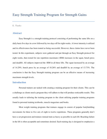
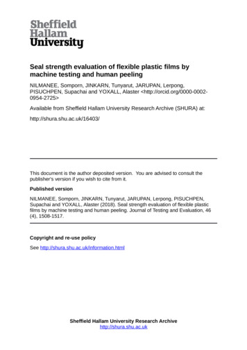
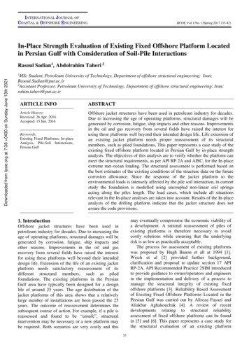
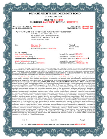
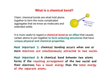
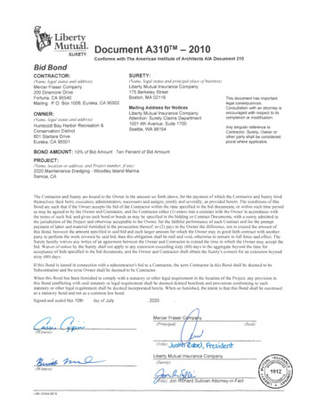
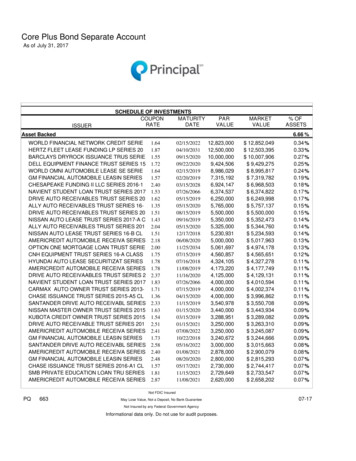
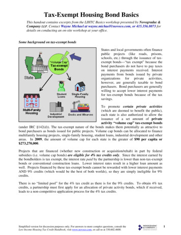
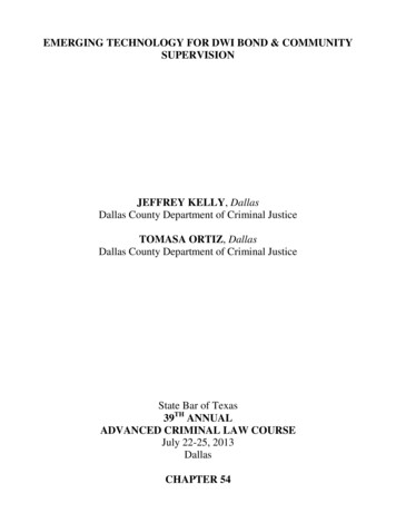
Polymer Engineering Company Ltd.Page 1 of 9INTRODUCTIONAt the request of PREDL Systems North America Inc. (PREDL), Polymer Engineering Company Ltd. (PEC)conducted a test to measure pull strength of the attachment to standard cast concrete of a proprietary,chemo-curable, sewer resistant resin liner. According to the information supplied, the specimenpreparation followed PREDL specifications for manufacturing precast sewer line manholes.The objective of this test was to demonstrate the bond strength of the PREDL liner to concrete andobtain the value of this strength for two similarly made specimens.Two cast concrete specimens used in the described experiment were made by PREDL together with therequired testing assembly hardware. The testing assembly was designed and made by PolymerEngineering in cooperation with Acuren Inc., who also conducted this testing in its facility in RichmondBC.SPECIMEN PREPARATIONThe PREDL liner system used in production as well as in testing described in this report contains thefollowing important elements:1. Liner made from proprietary PREDL resin. The resin is urethane cured polyester which could becharacterized by its FTIR spectrum shown in Figure 1.2. Bonding Bridges (Figure 2) which are the most important elements of the PREDL bonding systemare injection moulded from polypropylene homopolymer. Typical properties of injection mouldedgrade polypropylene homopolymer are shown in Table 1.3. Cast concrete made according to the standard PREDL specification.During samples preparation, the standard PREDL procedure was followed. The first layer of the liner wassprayed on the releasing substrate about 16” x 16” (40 x 40 cm) with thickness of about 80 mils (2 mm).After partial curing, a second layer was sprayed to a total thickness of the liner of about 1/4” (6 mm) andthe bridges were inserted into the liquid resin to the point that the flat top of the bridge came in contactwith the first layer. The bridge pattern created a square network with the bridge’s distance ofapproximately 6” apart (Figure 2). Finally, gravel was partially imbedded into the wet resin, sprayedlightly by a final layer of liner resin and left to cure. The liner and Bonding Bridges assembly were curedfor at least 24 hours (usually a few days), inserted into the specimen’s mould (Figure 3) and casted inconcrete. Each specimen was cured for over 30 days at room temperature and normal plant humidity.When this concrete was tested for compression (FORNEY F-1100KN -INT 120 VED) after 28 days ofcuring, it showed an average strength of 55.4 kN (Figure 4).The surface of the liner covering the cured specimens was then sanded and bonded with epoxy resin tothe clean the surface of the 3/4” (19 mm) thick steel plate with 12” x 12“ (30.5 x 30.5 cm) dimensions.This plate was part of the testing assembly and used for pulling the liner from the concrete during thetest. Before the plate and liner were bonded, the 3/4” treated bolt was inserted as an element ofattachment to the testing machine in the center of the plate (Figure 5). To allow good contact of theplate with the liner, 1.5” x 1.5” (3.7 x 3.7 cm) of the liner was removed from the center (Figure 6) andthe exposed concrete with cut plastic was coated with silicone rubber to eliminate the plate bond and
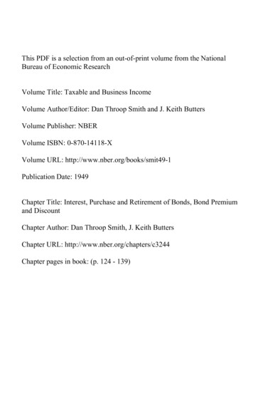
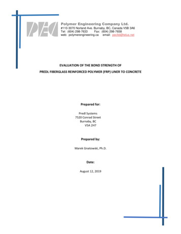
Page 2 of 9Polymer Engineering Company Ltd.the direct interaction with epoxy and concrete in the vicinity of the bolt. After 4 days of epoxy curing,the liner was scored to the concrete along the steel plate edge.Following an additional day of epoxy curing, specimens were taken to Acuren for testing.BONDING TESTINGTo test the bond strength between liner and concrete, the specimen was placed under the table of a120,000 lb Satec tensile tester. The bonded plate with the exposed threated bolt was connected to theupper grip and machine load cell with 3/4” threated steel rod using an appropriate steel connector. Theload cell recorded stress during the test and grip movement. Specimen assembly in the testing machineand performance of the liner bond during the test are shown in Figures 7 & 8. Speed of the gripsseparation of the tester was set up in such way that bond failure occurred between 30 s to 5 min fromthe beginning of the stress build up. Time associated with an initial relatively slow increase of the forceup to a few hundred pounds was ignored and treated as a preload. After testing was completed,specimen 2 was removed from the machine and liner was fully separated from the concrete forinspection (Figure 9)RESULTSThe bond strength during testing for specimens 1 and 2 were 15,148 lb and 10,823 lb respectively withan average value of 12,986 lb as shown in Acuren testing report (Figure 10). The average of the linerbonding strength was calculated as 91.6 psi when the liner surface, which was in contact with concreteand plate (141.75 in2), was taken under consideration.NOTICEThis report was prepared by Polymer Engineering Company Ltd. All the described tests and technological applications wereperformed in accordance with our best knowledge and the results represent our independent judgment. Furthermore, PolymerEngineering Company Ltd. hereby disclaims any and all warranties, expressed or implied, including the warranties ofmerchantability and fitness for a particular purpose, whether arising by law, custom, or conduct with respect to any of theinformation contained in this report. In no event shall Polymer Engineering Company Ltd. be liable for incidental orconsequential damages because of any information contained in this report. Liability of Polymer Engineering Company Ltd. islimited to fee paid only.
Page 3 of 9Polymer Engineering Company Ltd.Table 1. Typical properties of the injection moulding grade homopolymer polypropylene resinPropertyPhysicalDensityFlexural ModulusMechanicalTensile Strength at YieldTensile Elongation at YieldImpactNotched Izod Impact Strength (23 C)HardnessRockwell Hardness, (R-Scale)ThermalDeflection Temperature Under Load, (0.46N/mm²)Title:Method of TestingASTM D792ASTM D790ASTM D638ASTM D638ASTM D256ASTM D785ASTM D648Value0.90 g/cm³2000 MPa39 MPa8%30 J/m110120 CPREDL liner resin 001000Wavenumbers (cm-1)Polymer Engineering Company LtdFigure 1. FTIR spectrum of cured PREDL liner resin.Collection time: Wed Aug 07 12:04:03 2019 (GMT-07:00)
Page 4 of 9Polymer Engineering Company Ltd.ABCFigure 2 A-C. Bonding bridges, general view (A) andbridge cross-section (B) Bonding bridges attached tothe liner ready for concrete casting (C)Figure 3. The mould used for making the specimen forthe bonding test ready for concrete pouring. Pleasenote inserted liner with bonding bridges
Polymer Engineering Company Ltd.Figure 4. Concrete compression strength test resultsPage 5 of 9
Polymer Engineering Company Ltd.Page 6 of 9Figure 5. The Steel plate used as part of the testing assembly before attachment to the liner. Theinserted bolt for connecting the plate to the testing machine is marked with an arrow.Figure 6. The cuts in the liner to accommodate a head of the bolt are marked with arrows.
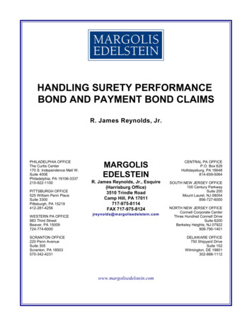
Page 7 of 9Polymer Engineering Company Ltd.213A7833865 49BCFigure 7A-C. Assembly of specimen for testing on Satec machine (A). Satec machine stationary table (1)the machine’s moving cross-arm with cell load and grip (2). The tested concrete specimen (3) withbonded liner (4) and attached steel plate (5). The coupler (6) between connecting rod (7) and the boltattached to the plate. Wooden block used as a spacers (8). Plywood and stripes securing the specimen(9)
Page 8 of 9Polymer Engineering Company Ltd.Figure 8. The specimens at the end of the test. Visible fracture and delamination of the liner markedwith arrow.1114242131412111421Figure 9. Separated surfaces of the liner (left) and concrete (right) in specimen 2. Visible the BondingBridges (1), Fractured liner (2), Clear silicone rubber coated liner’s cavity harboring connecting bolt head(3), Areas with limited bond between liner and concrete (4).
Polymer Engineering Company Ltd.Page 9 of 9Figure 10. Testing report for Specimen 1 (Block 1) and Specimen 2 (Block 2). Dyspleyed are the test’sreport maximum loads which are associated with bonding fracture between liners and concrete: 15,148lb for Specimen 1 and 10,823 lb for Specimen 2.
120,000 lb Satec tensile tester. The bonded plate with the exposed threated bolt was connected to the upper grip and machine load cell with 3/4” threated steel rod using an appropriate steel connector. The load cell recorded stress during the test an